Collaborative User Interface Generation. Alfonso Garcia Frey, Jean-Sebastien Sottet and Alain Vagner. Luxembourg Institute of Science and Technology (LIST).
Proceedings of the 2015 IEEE 19th International Conference on Computer Supported Cooperative Work in Design (CSCWD)
A Multi-Viewpoint Approach to Support Collaborative User Interface Generation Alfonso Garcia Frey, Jean-Sebastien Sottet and Alain Vagner Luxembourg Institute of Science and Technology (LIST)
5, avenue des Hauts-Fourneaux L-4362 Esch/ Alzette, Luxembourg Email: {alfonso.garcia.jean-sebastien.sottet.alain.vagner}@list.lu Abstract-Human-Computer Interaction (HCI) addresses the
In particular, the fixed representations, the implicit links
study, planning and design of the interaction between people
between them and a restricted view of the global process, limit
and computers through Vser Interfaces (UIs). The co-design and
the comprehension of stakeholders and act as obstacles in the
co-development of these VIs involve different stakeholders as
Devewpers, Functional Analysts, Usability Experts
among others,
all of them responsible for different VI elements (respectively
implementation,Junctional requirements, usability).
Collaboration
between stakeholders has been identified as a key factor for VI design and development.
co-design and co-development of VIs. This article explores a first approach on how to support the VI development and design processes to reduce their com plexity and cost. Firstly, we argue that collaboration between different stakeholders requires specific viewpoints expressed in
This article proposes a multi-viewpoint approach to support collaboration in a VI co-design and co-development process. The article discnsses the process itself and the different viewpoints
their own language. These languages address the concepts and objects manipulated by the stakeholders. Secondly, that colla boration could benefit from explicit links between stakehol
manipulated by all the involved stakeholders. We propose an im
ders' concerns. To this end, we propose a Model-Driven Multi
plementation of our approach in a model-based multi-viewpoint
Viewpoint approach to improve such collaborative aspects.
prototype. We show the feasibility of this approach implementing it on a case-study and a multi-viewpoint prototype.
The approach is described as follows. First section intro duces our Vser Interface Generation Process, including the
PROBLEM AND MOTIVATION
necessary Model-Driven Engineering (MDE) foundations as
The development of Vser Interfaces (VIs) is a complex
collaboration aspects. Third section introduces our approach
I.
task. As stated by
[1] "VI development for enterprise appli
cations is a time-consuming and error-prone task". Moreover, approximately
50% of development resources are devoted to VI implementation tasks [2]. One reason of such complexity is the diversity of stakeholders involved in the co-design and co-development of such VIs. For instance, while
usability experts focus on usability criteria concerns such as cognitive workload I or guidance2, VI developers need to know how these criteria apply to their own concerns, i.e., what cognitive workload or guidance mean in terms of, for instance, graphical widgets. The same problem of collaboration exists among other stakeholders such as
designers and developers. As an example,
designers' mockups directly impact developers' concerns (for instance, how the mockup of a VI is implemented in a specific device). Moreover, this problem of collaboration can affect multiple stakeholders at the same time; consider the case where the usability expert wants to change a widget in a mockup to satisfy some usability criteria. It will impact not only the designer's concerns (the elements of design inside mockups) but also the developer's concerns (the implementation of widgets represented in such mockups). The
representation
of
each
concern
(e.g.,
diagrams,
ideograms, etc.) and the relationships to other stakeholder's concerns are barriers for VI development and for collaboration because they are often fixed or implicit.
well as all the involved stakeholders. Second section details and its implementation on a case study. The article ends discussing perspectives and future work. II.
VSER INTERFACE GENERATION PROCESS
A. Model-Driven Engineering MDE is a "Software development methodology which focuses on creating and exploiting
[...] models, that are,
abstract representations of the knowledge and activities that ,, govern a particular application domain 3. We rely on MDE for our proposition for several reasons: different frameworks and languages have been proposed to structure the way VIs are generated from models
[3], [4], where these are successively
transformed through model transformations until the code of the VI is generated. This provides easier evolutions and reuse
[5], dynamic adaptation of the VI to the context of use [6], [7], end-user programming [8], greater quality [9], [7], [10] and support generation [11], [12], [13] among others. A model is defined
[14] as "An artefact that conforms to
a metamodel and that represents a given aspect of a system". Indeed, concerns are also aspects of the system. Following this definition, we capture into (and represent with) models all the stakeholders' concerns. The representation and manipUlation of these concerns (i.e., models conforming to some metamodels) is done through the concept of Viewpoint. Viewpoints capture the interconnections between different concerns and their rela tionships and made them manipulable by different stakeholders at the same time, thus improving collaboration.
I http://en.wikipedia.orglwikilCognitive_load 2http://www.iso.orgliso!home/store/cataIogue_tc/catalogue_detail.htm?
3http://en.wikipedia.orglwikilModel-driven_engineering
csnumber39080
425 978-1-4799-2002-0/15/$31 ©20l5 IEEE
I
I
� 1 .... llcOdel I
2
� LJ C .I C i nt A le
-
Functional Analyst
3
4
t) � t) #A Designer Usability Expert
Domain Expert
c=J State � Transformation III Stakeholder Fig. 1.
-
Engineer
Viewpoint 0
[15], necessary means to manipulate (transform) models.
We thus rely on transformations in order to manipulate con
7
eveloper
Collaboration
n
Cooperation
1
Mapping
IFM
These two inter-related models are created in a first step
The UI is obtained by transformation, i.e., some input models are transformed into some intermediary models that can be transformed as well. The process continues until the code of the UI is generated. The models used as input usually capture user activities (or users tasks) as well as the manipulated data (application domain concepts). All the models (both input and intermediary ones) represent a particular sub-domain of UI engineering manipulated by specific stakeholders. There are several UI generation approaches relying on a different set of
[3], [18] and [4].
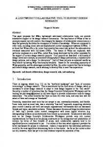
We propose a model-driven UI generation process based on multi-viewpoints (figure
1). This process generates a UI
starting with two input models: the Domain model and the Interaction Flow Model (IFM). The latter is interoperable with
[19]. References (or mapping) between the
Domain and the IFM model are also provided. The Domain model represents the domain elements manipulated by the application (as provided by classical domain expert). It can be represented with a UML class model. The
IFM
represents
the interaction flow of the application and conforms to the
ContalnerStat
states
o. *
1, part 2). An excerpt of the CUI 3. The CUI depicts the appli
cation "pages", the navigation between them and their content (graphical widgets). The CUI model is independent of the final implementation of any graphical element. The resulting CUI model can be modified in a third step (figure
1, part 3) if
necessary. Afterwards, the CUI model is transformed into an Implementation Specific Model (ISM) that takes into account platform details (figure
1, parts 4 and 5). These platform details
refer to UI toolkits such as HTML/JQuery, Android GUI, etc. The UI code is generated in a final step (figure
1, part 6)
in a model-to-text transformation according to the ISM. For instance, if the ISM represents the Java/Swing metamodel, the generated code will be Java plus swing widgets4. The same applies for other ISMs as the aforementioned UI toolkits. The separation into these steps provides several advantages. To mention a few, changes into platform specific (meta)models as ISM do not directly impact the design choices at previous steps. For example, the choice of a standard graphical widget such as radio buttons or drop-down lists remains the same independently of the target platform. Moreover, several plat forms can be simultaneously considered through several ISMs, each of them with specific generated code. However, at each models (including the two input models); going backwards and modify the models or transformations is still possible.
states
State 0
model transformation (figure
metamodel is shown in figure
step one could identify some misconceptions of the previous
StatesMode
0.,*
1, part 1). They are transformed in a second step into a
Concrete User Interface model (CUI) with a single model-to
Model-driven UI design is a multi-stakeholder process [16], [17] where a User Interface is generated from a set of models.
the OMG standard
2. The relationship between IFM
specific interaction step. (figure
Model-Driven UI Generation Process
models, for instance
metamodel in figure
and Domain represents which elements are manipulated in a
cerns and viewpoints. B.
D
6
Model-Driven VI generation process
The another key concern in MDE are model transforma tions
5
TransformatIOn
Transformation Engineer
I
1 target
1 source
C.
Transition
transitions
name; EString
0..*
CI
Roles and Stakeholders The stakeholders involved in the previous process need to
type: TransitionTypes
cooperate and collaborate at some points (figure
1). Their roles
and the manipulated concerns are described next. CommandStat
In utState
§ OutputState _�"-C"5el",: e"" ctl""on e: St ",a :: t", e�--1 Cl
Fig. 2.
m ulti pleSelection
1) Functional Analyst: Functional Analysts are in charge
EBoolean
of the functional requirements both in terms of interaction
The IFM metamodel in Ecore notation.
4https:lldocs.oracle.comljavaseitutoriaVuiswing/index.html
426
implementing the function signatures. III.
VIEWPOINTS AND COLLABOR ATION MODELS
Some stakeholders collaborate at different stages of the process (figure 1). To improve this, collaboration needs to be explicitly considered as well. One accepted model for describing collaboration is the 3C model by [20] refined by [21]. According to the latter, collaboration encompasses: Fig. 3.
Cooperation, i.e., "the joint operation of members of the group in a shared space, seeking to execute tasks, and generate and manipulate cooperation objects."[21],
Excerpt of the CUI metamodel in Ecore notation.
and application requirements. Functional analysts can define (usually along with the client) the interaction flow of the application, i.e., the states in which the UI is decomposed. The IFM is identified and manipulated by functional analysts in our process. They are also responsible for the definition of the function signatures that trigger functional core methods. This denotes how the functional core of the application and the UI are both integrated into the final product. In our UI generation process, they identify and fix the signature functions that interface the functional core. A function signature consists in the function prototype. It tells the developers the general information about the function, its name and parameters.
2) Domain Expert: The domain expert specifies the con cepts (or objects) manipulated by the application as well as their properties or attributes. The main concern of the domain expert is thus the domain model, usually represented in "UML class"-like diagrams. They usually act in collaboration with functional analysts, defining the function parameters from the domain model (or can be the functional analysts themselves). 3) Designer: The designer is associated with the design of the UI in a variety of media, with a focus on producing a system to respond to the user's experience. Designers usually collaborate with usability experts (sometimes the same person plays both roles). 4) Transformation Engineer: They are responsible for writing model transformations in some model transformation language. They have to collaborate with people responsible for the input and the output of the transformations. For instance, if they design a transformation from IFM to CUI, they have to define with the designer which CUI elements the transformation has to target.
5) Usability Expert: The usability expert usually assesses usability quality on the produced mock-ups or on the generated UIs. Indeed, this job can be completely disconnected from the modelling phases. However, the usability knowledge could be of great value to help UI designers to produce better interfaces. Usability experts can eventually take part in the design of inter action flow models but also during the transformations phases producing executable UIs (i.e., code generation), working on the transformations with other stakeholders' concerns. 6) Developer: Developers are responsible for implement ing functional aspects previously identified by functional ana lyst(s). Developers can also discuss with functional analysts of the relevance of defined functions and potential discrepancies between requirements and technical feasibility. The main con cern we have identified for the developers is the source code
427
Coordination or the "inter-dependencies between tasks that are carried out to achieve a goal" [21] and Communication, which is the "Conversation to negotiate and make decisions through an augmentation process" [21]. In the context of model-based UI development coordination can also be understood as the process (in a computational sense) organising cooperation actions. Communication also in volves the exchange of information and knowledge among the stakeholders. Awareness is fostered by the three components. Results showed [22] that "the highest degree of users' aware ness about their activities and other system users contribute to a decrease in their errors and in the inappropriate use of the system". Thus, a way of providing awareness in a model based UI generation process is to provide viewpoints that support flexibility in four ways. First, by making stakeholders' concerns directly manipulable. Second focusing only those concerns that are relevant for the stakeholder for a given task. Third, providing means for adapting the concern represen tations to the specific stakeholders if necessary. Finally, to support collaboration via communication, coordination and co operation, viewpoints should be synchronized when necessary (awareness). These requirements have been implemented in the prototype we developed for the next case study. IV.
CASE STUDY
We have modelled an online shopping website using our UI generation process. The website provides several catalogues to the users, each of them containing a family of products. Once one or more products have been added to the cart (products can be either added or removed from the cart), users can checkout. To checkout or modify the account details, users are requested to login.
A. Collaborative Process We follow all the modelling steps of our model-based UI generation process (figure 1). During the first step, the functional analyst and the client cooperated to design a first version of the IFM through the same viewpoint. We decided to use a Tangible User Interface (TUI) to engage the client into the modelling process (figure 5). As shown in [23] TUIs are good for collaboration and cooperation; they facilitate the negotiation and promote the commitment about decisions taken. TUI provides a better involvement of stakeholders by the possibility of physically engaging them with graspable objects [24]. Thus, TUIs help functional analysts in assessing the requirements with the client by reaching agreements about models.
AMes Editor v.D.O! • Google Chrom�
I) .6Jo.IE:I Edittlf v,O,Ol
!
c"5 loc.lhos
... Ale
Edit�- VIew
.
0001
Examples
About
New Attnbu[e5 U5[
Comma"oSuTt
AME
f """ ,uro, ; -'j l1Uopl£hUC; s h t: 'I :lolto.. 1IIfora.'1ttue-·'1 ( r ) .. ,
V.,."".;nt
""'Hlo",VllIcldlell 'Ioar
•
l�
iJ
..... 1'
Inu'lo al'llll ���r