(CMA) by a phase-locked loop to compensate for carrier fre- quency offset. .... The carrier recovery loop generates Uk = e jÏk, where Ïk is the receiver's esti-.
A Multidimensional Phase-Locked Loop for Blind Equalization of Multi-Input Multi-Output Channels John R. Barry and Anuj Batra School of Electrical and Computer Engineering Georgia Institute of Technology, Atlanta, Georgia 30332-0250 Abstract — We present a new technique for blind equalization of multiple-input multiple-output (MIMO) communication channels. In scalar channels it is common to follow a blind equalizer adapted according to the constant-modulus algorithm (CMA) by a phase-locked loop to compensate for carrier frequency offset. We generalize this structure to multiple dimensions, and propose to follow a blind MIMO equalizer adapted according to the vector CMA by a multidimensional phaselocked loop. We show through simulations that the new technique can converge much faster than prior techniques. I. I NTRODUCTION A multiple-input, multiple-output (MIMO) channel model arises whenever a receiver observes signals from multiple transmitters through multiple sensors. Depending on the application, the interference among the transmitted signals may be called cochannel interference, crosstalk, or multiuser interference, and the mitigation of this interference has motivated extensive research [1–9]. A simple MIMO channel model is shown in Fig. 1. The channel input xk is a sequence of n × 1 vectors whose components represent the symbol sequences of n different users. The channel transfer function is H(z). For simplicity we neglect noise, and we assume that H(z) is square, so that the dimension of the channel output rk is also n. The objective of a MIMO equalizer, as shown in Fig. 1, is to mitigate both intersymbol interference and co-channel interference. Most prior work in MIMO equalization theory has assumed that the channel responses are known or that a training sequence is available. Only recently has the problem of blind MIMO equalization (without training) been addressed, and several blind algorithms based on vector generalizations of the constant-modulus algorithm (CMA) have been proposed [10,11]. Just as the scalar CMA is invariant to phase rotations, the vector CMA [11] is invariant to unitary transformations. In [10,11], this unitary rotation was avoided by modifying the xk
H(z)
rk
yk
C(z) ψ
Fig. 1. A MIMO channel and a blind MIMO equalizer. This research was supported by the Center for Research in Applied Signal Processing.
vector CMA cost function in an attempt to force each component of the vector-valued signal to have a constant modulus. This pointwise technique is directly analogous to the scalar algorithm of [12]. In contrast, in this paper we propose to identify the unitary rotation using a multidimensional phase-locked loop (PLL). This approach is a multidimensional generalization of the common scalar receiver consisting of a CMA equalizer followed by a decision-directed carrier loop [13]. In Sect. II we review two blind equalization algorithms for MIMO channels: the vector CMA [11] and the combination CMA [10]. In Sect. III we review the structure of a scalar PLL, and in Sect. IV we derive the multidimensional PLL. In Sect. V we present numerical examples. II. B LIND E QUALIZATION
FOR
MIMO C HANNELS
Consider the adaptive MIMO linear equalizer structure shown in Fig. 1; it is a transversal filter with L matrix-valued taps described by the matrix CkT = [C0,k C1,k … CL–1,k]. Let RkT = [rkT rk–1T… rk–L+1T] be a vector of equalizer inputs, so that the equalizer output at time k is yk = CkTRk. A. Vector Constant Modulus Algorithm
As described in [11], the vector CMA for blind equalization is a natural extension of the conventional CMA [14] to MIMO channels. The vector CMA cost function is: J = E[(|| yk ||2 – M)2],
(1)
where M = E[|| xk ||4] ⁄ E[|| xk ||2], and the weight update equation for the vector CMA is: Ck+1= Ck – µRk*ekT,
(2)
where µ is the step size and the error signal is defined as: ek = yk (|| yk ||2 – M).
(3)
The cost function (1) is invariant to unitary transformations. In other words, if F(z) = C(z)H(z) is the overall system transfer function from the channel input to the equalizer output, then the cost function will be minimized when F is any unitary matrix. If the components of xk are selected from an alphabet with constant modulus, then F need not be unitary to minimize J. For example, a diagonal matrix F = diag[λ1, λ2, …, λn] will minimize J when
∑ |λi|2 = n
and the alphabet is constant modulus. In addition, if the k-th row of F contains only one nonzero entry of the form e jθk for some θk, such as 1 0 , then F will also mini1 0
mize J.
As appeared in International Conference on Communications, vol. 3, pp. 1307-1312, Dallas, June 1996.
both to have unity magnitude before estimating the phase difference, yielding an estimate of [15]:
However, if the alphabet is not constant modulus and the channel is memoryless, then we hypothesize that only a unitary matrix will minimize the vector CMA cost function:
εk = ∠{x*z} = sin–1 [Im{x*z}],
Conjecture. If the components of x are independent and uniformly distributed over a discrete alphabet with non-constant modulus, then y = Fx minimizes the cost function J = E[(|| y ||2 – M)2] if and only if F is unitary.
where x = xˆ k ⁄ | xˆ k| and z = zk ⁄ |zk|. The phase estimate εk is then passed through a loop filter with constant transfer function L(z) = K. (A constant loop filter is sufficient to track a constant phase error, but a higher-order filter is necessary to track a constant frequency error.) The loop filter output drives a VCO whose output is Uk. By definition, the VCO output Uk is related to its input Kεk by:
B. Combination of Vector and Pointwise CMA
To prevent the equalizer from converging to a unitary matrix rather than the identity matrix, Oda and Sato modified the vector cost function by adding a pointwise component, yielding the socalled combination CMA cost function [10]:
Uk = exp{ j
n
2
2
Jc = AE[(|| yk || – M) ] + B (i)|4]
∑ E[(|yk(i)|2 –
i=1
Mi)2],
(5)
k
k
exp{ jKεi}. Σ Kεi} = iΠ =0
(6)
i=0
Therefore, a VCO can be viewed in two ways: as a sum-accumulator followed by a complex exponentiator, or as a complex exponentiator followed by a product-accumulator. We choose the second viewpoint to facilitate its generalization to vector signals.
(4)
E[|xk(i)|2]
where Mi = E[|xk ⁄ and A and B are positive constants. The purpose of the first term in (4) is to force yk to have a constant modulus, and the purpose of the second term is to force each component yk(i) of yk to have a constant modulus. Although a unitary matrix will minimize the first term, it will not minimize the second term. The combination CMA reduces to the pointwise CMA when A = 0 [11].
As shown in the figure, we define the rotation detector as the cascade of the phase detector, loop filter, and exponentiator. It’s output Tk = exp{ jKεk} rotates a fraction K of the way from xˆ k to zk. The positive constant K is typically much less than unity. Note that, using (5), Tk can also be expressed as Tk = (x*z)K.
Although originally defined for multidimensional systems, the combination CMA can be used in a complex-valued scalar system by viewing it as two-dimensional real-valued system. Indeed, this viewpoint is adopted in [12] to eliminate carrier phase offset. However, it is much more common to append a phase-locked loop after a conventional scalar CMA equalizer to eliminate carrier phase offset [13].
IV. A M ULTIDIMENSIONAL P HASE -L OCKED L OOP We now propose a new blind equalization technique for MIMO channels by generalizing the scalar PLL of the previous section to multiple dimensions. Specifically, rather than modifying the vector CMA equalizer to avoid unitary rotations, we propose to append a multidimensional PLL to identify and eliminate any rotation.
The simplicity and effectiveness of the CMA equalizer-PLL cascade in scalar systems has motivated us to propose a similar structure for MIMO systems, as described in Sect. IV. Before describing the MIMO PLL, however, we first review the components of a scalar PLL.
Because the vector CMA cost function is invariant to unitary transformations, the equalizer output yk after convergence may be related to the transmitted symbol vector xk by a unitary matrix. We propose to append a multidimensional generalization
III. A S CALAR P HASE -L OCKED L OOP
rk
Perhaps the most popular structure for blind equalization of scalar channels is a CMA equalizer followed by a decisiondirected PLL to track phase error, as illustrated in Fig. 2-a [13]. The scalar CMA cost function is insensitive to the phase of the received signal, so that any carrier frequency offset between the receiver local oscillator and the transmitter oscillator will cause the constellation after the equalizer to rotate. Let θk be the phase offset at time k, so that after convergence the equalizer output yk is related to the transmitted symbol xk by yk = e jθkxk. The carrier recovery loop generates Uk = e jφk, where φk is the receiver’s estimate of θk. If φk ≈ θk, then the product zk = Uk*yk reduces to zk ≈ xk, and decisions based on zk will be accurate.
C(z)
^
zk = Uk*yk
yk
xk DEC
*
ψ Uk
Π
Tk
e j{ ⋅ }
εk K
Phase Detector
Rotation Detector VCO
(a) rk
C(z)
DEC
†
ψ Uk
As shown in Fig. 2-a, the decision-directed carrier loop generates Uk by first estimating the phase difference εk between the slicer input zk and slicer output xˆ k using a phase detector. To deal with the noisy case when zk and xˆ k may have different magnitudes, it is common for the phase detector to normalize
^
xk
zk = Uk†yk
yk
Π
Tk
Rotation Detector
(b) Fig. 2. A CMA equalizer followed by a decision-directed PLL for (a) scalar channels; (b) MIMO channels.
2
for some β ∈(– π, π]. Therefore, the set of all unitary matrices Tk mapping x to z is given by:
of the scalar decision-directed phase-locked loop to generate an estimate Uk of this unitary matrix. If this estimate is accurate, then the product zk = Uk† yk [where ( ⋅ )† denotes conjugate transpose] reduces to zk ≈ xk, so that decisions based on zk will be accurate.
Tk = V
As shown in Fig. 2-b, the MIMO receiver generates Uk in a way similar to the scalar receiver. The key component of the loop is the rotation detector, whose output Tk is a unitary rotation matrix that approximately rotates a fraction of the way from xˆ k to zk. Specifically, let z´ be a vector between xˆ k and zk: z´ = λzk + (1 – λ) xˆ k,
(8)
Then we define Tk as a unitary matrix mapping x to z. Unlike the scalar case, Tk is not unique. We now derive the family of unitary matrices Tk mapping the unit-length vector x to the unit-length vector z. Let p denote the inner product: (9)
Because x and z are unit length, p satisfies |p|≤ 1. We consider the cases |p| = 1 and |p| < 1 separately, starting with |p| = 1.
Tk = V
0
0
J
V† ,
Tk = I + x , y
(10)
(when |p| = 1).
2
p
–
1 – |p|2
p*
0
e jβ
,
(16)
(17)
In this section we present simulation results for three experiments, and compare the performance of the multidimensional PLL with that of the combination and pointwise CMA equalizers. In all cases we assume a noiseless 2 × 2 system, with the two transmitters being independent and uniformly distributed over a 16-QAM alphabet. We assume that the combination CMA parameters are A = 4 and B = 1, and that each equalizer is initialized to the identity matrix. The modulus parameters for a twouser 16-QAM system are M = 23.2 and Mi = 13.2.
2
0
i=0
V. S IMULATION E XAMPLES
1 – p ]T must have the
1
k
Π Ti ,
We remark that a second-order loop is not necessary, and that the first-order MPLL described above is sufficient for our purposes, because the unitary matrix being estimated after convergence will be a constant.
(12)
1 – |p|2
(|p| < 1). (15)
|p|– 1
U–1 = I, Uk = TkUk–1 .
2
˜ = R
1 – |p|2
x† y†
which can be implemented recursively:
(11)
1 – p , 0, 0, …, 0]T, respectively. It can be shown that any
unitary matrix mapping [1, 0]T to [p, form:
– p 2 |p| 1 – |p|
Uk =
(The basis vector y should not be confused with the equalizer output yk.) Let V = [x, y, v3, v4, …, vn] be a unitary matrix whose columns form an orthonormal basis of the entire space. In terms of this basis, x and z are given by the vectors [[1, 0, …, 0]T and [p,
(14)
As in the scalar case of (6), the MIMO VCO accumulates the rotation vectors, so that the receiver’s estimate of the overall rotation matrix at time k is given by:
On the other hand, if |p| < 1, then the span of x and z is a two-dimensional subspace. Let us introduce a basis {x, y} for this subspace, where from the Gram-Schmidt procedure we have: y = (z – px) ⁄ 1 – p .
V† ,
In summary, the rotation detector of Fig. 2-b is defined by (15) and (11), together with (7) – (9) and (12), and is parameterized by the constant λ.
where J is an arbitrary (n – 1) × (n – 1) unitary matrix. Because x and z convey information about the one-dimensional subspace spanned by x only, we should choose J so as not to affect the vectors orthogonal to this subspace; in other words, we should choose J = I, in which case (10) reduces to: Tk = I + (p – 1)xx†
J
p– 1
If |p| = 1 then z = px. Let V = [x, v2, v3, v4, …, vn] be a unitary matrix whose columns form a basis for the entire space. In this case, the set of all unitary matrices Tk mapping x to z is given by: p
0
Again, because x and z convey information about the subspace spanned by x and z only, we choose J so as not to affect the vectors orthogonal to this subspace; in other words, we choose J = I. The choice of β is not as obvious. Observe from (13) and (14) that detTk = e jβ when J = I and |p| < 1. On the other hand, from (11) we see that detTk = p when |p| = 1. This suggests that, to be consistent in our choice of β as |p| approaches unity, we should choose β = ∠p = sin–1 [Im{p ⁄ |p|}]. ˜ – I, The choice β = ∠p also minimizes the Frobenius norm of R which is intuitively pleasing because we expect Tk to approximate I near convergence. For these reasons we choose β = ∠p in our algorithm. With J = I and β = ∠p, (14) reduces to:
where λ ∈ (0, 1), and define the unit-length vectors x and z by:
p = x† z.
0
where β ∈(– π, π] and J is an arbitrary (n – 2) × (n – 2) unitary matrix.
(7)
x = xˆ k ⁄ || xˆ k || and z = z´ ⁄ || z´ ||.
˜ R
(13)
3
output one versus time for the three algorithms. (The results for the imaginary part and those for output two are not shown but are qualitatively similar.) In Fig. 5 we show the constellation diagrams (for time 200 to 400) before the PLL, after the PLL, for the pointwise CMA, and for the combination CMA. These figures show that the MPLL converges quicker and more abruptly than the other techniques.
A. Experiment One: Memoryless Unitary Channel
In the first experiment we consider a channel matrix that is unitary, so as to demonstrate the speed with which the multidimensional PLL can identify and eliminate unitary transformations. Specifically, consider a memoryless two-user system with ˜ , where R ˜ is defined in (13) with a unitary channel matrix H = R –1 parameters p = 0.5 + jπ and β = π ⁄ ln2. Assume that the equalizer has one tap, and assume a zero step size for vector CMA and a step size of µ = 10–4 for both pointwise and combination CMA. (A nonzero step size for vector CMA will not appreciably affect the results, because the output of a unitary channel already minimizes the vector CMA cost function; hence, a nonzero step size will merely cause the equalizer to hover about the identity matrix.) The MPLL parameter was chosen to be λ = 0.1.
B. Experiment Two: Memoryless Near-Singular Channel
In this experiment we consider a memoryless two-user system with the following channel matrix: H=
0.5
Ui,2,1
0
0
100
200 Time
Ui,1,1
300
Output 1 400
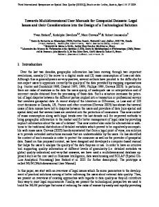
Fig. 3. PLL coefficients versus time for experiment one.
Real{yk(1)}
200
400
600
800
1000
0 -5 5
Real{yk(1)}
(a)
0
.
(19)
Output 2
AFTER MPLL
5
1 0
(b)
0
200
400
600
800
POINTWISE
-5
1 0
1000
0
(c)
COMBINATION
Real{zk(1)}
5 0
(18)
Assume step sizes of 8 × 10⁻⁴ , 5 × 10⁻⁴ , and 10–4 for vector CMA, pointwise CMA, and combination CMA, respectively. Assume a MPLL parameter of λ = 0.05.
Ui,2,2
Ur,2,1
–0.5
F=
Ur,2,2
Ui,1,2
.
VECTOR CMA
MPLL Coefficients
1 Ur,1,2
0
1 0.5
Although there is no crosstalk for the first user, the crosstalk for the second user is particularly severe, with the interference power exceeding the signal power by 6 dB. With this channel there is a tendency for some blind equalization algorithms to converge to an undesirable overall transfer function of:
In Fig. 3 we plot the eight MPLL coefficients {Re[Uij], Im[Uij], i,j = 1,2} versus time. Observe that the MPLL converges after only about 100 iterations. In Fig. 4 we plot the real part of
Ur,1,1
1
-5 0
200
400
600
800
1000
Time Fig. 4. Real part of output 1 versus time for experiment one: (a) vector CMA after MPPL; (b) pointwise CMA; (c) combination CMA.
Fig. 5. Constellations for experiment one (time 200 to 400).
4
In Fig. 6-a we plot the eight vector CMA equalizer coefficients {Re[Cij], Im[Cij], i,j = 1,2} versus time, and in Fig. 6-b we plot the MPLL coefficients {Re[Uij], Im[Uij], i,j = 1,2} versus time. Observe that the PLL achieves lock near time 500.
Output 2
VECTOR CMA
Output 1
AFTER MPLL
In Fig. 7 we show the constellation diagrams (from time 1000 to 1200) for the different algorithms. The constellations after the MPLL are clean, and the overall transfer function U† CvH converges approximately to the identity matrix. On the other hand, despite the fact that the constellations for the pointwise algorithm appear to be clean, the overall transfer function CpH converges approximately to the undesirable matrix of (19); thus, the pointwise equalizer is a failure, because both of its outputs lock onto the signal of user 1, ignoring the signal of user 2. C. Experiment Three: Channel with Memory
Consider a system with the following channel matrix: e j0.4π
0.7e–j 0.3π
0.3e j1.2π
0.9e j0.9π
+
0.3e–j 0.7π
0
0.4e j0.1π
0.1e j0.4π
z–1 . (20)
POINTWISE
H(z) =
Assume a five-tap equalizer, and assume step sizes of 10–4 , 10–5 , and 2 × 10⁻⁵ for vector CMA, pointwise CMA, and combination CMA, respectively. Assume a MPLL parameter of λ = 0.03.
COMBINATION
In Fig. 8 we plot the real part of output 1 versus time for the vector CMA with MPLL and combination CMA algorithms. In Fig. 9 we show the constellations for the various algorithms from time 4600 to 5000. As before, the MPLL converges faster than the other equalizers.
Fig. 7. Constellations for experiment two (time 1000 to 1200).
6
(a)
2
Real{zk(1)}
EQ. COEFFS
In each of the above experiments, the vector CMA with a multidimensional PLL converged faster than the combination CMA or the pointwise CMA. Although the simulations considered only a few sample channels, we expect faster convergence on a broad class of channels. Intuitively, this is because the channel matrix will almost always be closer to a unitary matrix
1 0 –1
–6 0
500
1000
0
1
5000
6
(b) Real{yk(1)}
MPLL COEFFS
(a)
0
0
(b)
0
–6
–.6 0
500 Time
1000
0
5000 Time
Fig. 8. Experiment three: Output 1 versus time for (a) MPLL; (b) combination CMA.
Fig. 6. Experiment two: (a) Equalizer coefficients for vector CMA versus time; (b) MPLL coefficients versus time.
5
(of which there are infinitely many) than to the identity matrix. Therefore, if the equalizer is initialized to the identity matrix, the overall transfer function starts out much closer to a unitary matrix than to the identity matrix; thus, the equalizer can converge much faster if it need only force the overall transfer function to be unitary. As illustrated dramatically in Sect. V.A, the MPLL is able to eliminate unitary transformations must faster than the pointwise and combination CMA equalizers.
VII. R EFERENCES [1]
W. van Etten, “An Optimum Linear Receiver for Multiple Channel Digital Transmission Systems,” IEEE Transactions on Communications, pp. 828-834, Aug. 1975.
[2]
J. Salz, “Digital Transmission Over Cross-Coupled Linear Channels,” AT&T Technical Journal, 64:6, pp. 1147, July-Aug. 1985.
[3]
S. Verdu, “Recent progress in Multi-User Detection,” in Advances in Communications and Signal Progressing, W. A. Porter and S. C. Kak, Eds. Springer-Verlag, New York (1989).
[4]
A. Duel-Hallen, “Equalizers for Multiple-Input ⁄ Multiple-Output Channels and PAM Systems with Cyclostationary Input Sequences,” IEEE J. Select. Areas in Comm.,” 10:3, pp. 630-639, Apr. 1992.
[5]
M. L. Honig, P. Crespo, and K. Steiglitz, “Suppression of Nearand Far-End Crosstalk by Linear Pre- and Post-Filter,” IEEE J. Select. Areas in Comm., 10:3, pp. 614-629, Apr. 1992.
[6]
D. D. Falconer, M. Abdulrahman, N. W. K. Lo, B. R. Peterson, and A. U. H. Sheikh, “Advances in Equalization and Diversity for Portable Wireless Systems,” Digital Signal Processing, vol. 3, no. 3, pp. 148-162, July 1993.
[7]
J. H. Winters, J. Salz, R. D. Gitlin, “The Impact of Antenna Diversity on the Capacity of Wireless Communication Systems,” IEEE Transactions on Communications, vol. 42, no. 2-4, pp. 1740-51, Feb.-April 1994.
[8]
J. Yang and S. Roy, “Joint Transmitter-Receiver Optimization for Multi-Input Multi-Output Systems with Decision Feedback,” IEEE Trans. Info. Theory, 40:5, pp. 1334-1347, Sep.1994.
[9]
P. A. Voois and J. M. Cioffi, “Multichannel Signal Processing for Multiple-Head Digital Magnetic Recording,” IEEE Trans. Magnetics, 30:6, pp. 5100-5114, Nov. 1994.
VI. S UMMARY After convergence of the vector CMA, the overall transfer function from the channel input to the equalizer output may be an arbitrary unitary matrix. To identify and eliminate this rotation matrix, we generalized the decision-directed phase-locked loop to vector-valued signals. The cascade of a blind MIMO equalizer adapted according to the vector CMA and a multidimensional PLL is a natural extension of a commonly used strategy for blind equalization of scalar channels. Simulation results show that the vector CMA with a multidimensional PLL can converge must faster than other known blind MIMO equalization algorithms.
Output 2
VECTOR CMA
Output 1
AFTER MPLL
[10] H. Oda, Y. Sato, “A Method of Multi-Dimensional Blind Equalization,” Intern. Symp. on Info. Theory, San Antonio, p. 327, 1993. [11] A. Batra, J. R. Barry, “Blind Cancellation of Co-Channel Interference,” IEEE Global Telecommunications Conference, Singapore, vol. 1, pp. 157-162, November 1995. [12] K. N. Oh and Y. O. Chin, “Modified Constant Modulus Algorithm: Blind Equalization and Carrier Phase Recovery Algorithm,” ICC´95, Seattle, pp. 498-502, May 1995.
POINTWISE
[13] N. K. Jablon, “Joint Blind Equalization, Carrier Recovery, and Timing Recovery for High-order QAM Signal Constellations,” IEEE Trans. on Sign. Proc., 40:6, pp. 1383-1398. [14] J. R. Treichler, B. G. Agee, “A New Approach to Multipath Correction of Constant Modulus Signals,” IEEE Trans. Acous., Speech, and Sign. Proc., 31:2, pp. 459-472, Apr. 1983.
COMBINATION
[15] E. A. Lee and D. G. Messerschmitt, Digital Communication, Second Edition, Kluwer (1994), p. 728.
Fig. 9. Constellations for experiment three (time 4600 to 5000).
6