Proceedings of the International MultiConference of Engineers and Computer Scientists 2014 Vol I, IMECS 2014, March 12 - 14, 2014, Hong Kong
A Navigational Aid System for Visually Impaired Using Microsoft Kinect Mahmud Ridwan, Ehtesham Choudhury, Bruce Poon, M. Ashraful Amin, Hong Yan
Abstract—Numerous attempts have been made to devise systems that make the work of a visually impaired person easier. These researches have focused on a number of issues such as path finding, obstruction detection, face recognition, sign recognition, to name a few. The aim of this paper is to outline a system, based on Microsoft Kinect that will provide some of these features in a unified manner. The system is based on a number of open source tools such as: OpenCV, OpenKinect, Tesseract and Espeak. Features that have been incorporated building this aiding tool are object detection and recognition, face detection and recognition, object location determination, optical character recognition and audio feedback. One of the key components of this research is to ensure considerable amount of accuracy and at the same time be extremely efficient in terms of hardware resource required. Since the system is an aggregation of multiple components, their accuracies are measured independently from online and offline point of view (where applicable). The best component (face recognition) showed an accuracy of 90%. The weakest component (text recognition) yielded an accuracy of 65%. The proposed system is able to detect and recognize face/text/chair in a frame within 2.25 seconds.
Index Terms--Navigational aid; Visual impairment; Human computer interaction (HCI); 3D camera; Kinect.
I. INTRODUCTION The proposed work here is motivated by the need of a navigational aid system for blind and visually impaired people. In spite of the success of computer vision technology in several other fields (such as robot navigation, surveillance, and user interface), very few computer vision systems and algorithms are currently employed to aid visually impaired people. However, computer vision and mobile computing are powerful tools with great potential to enable a range of assistive technologies for the growing population of blind and visually impaired. Recent technology developments in computer vision, This work is partially supported by City University of Hong Kong (Project 6987017). Mahmud Ridwan is with the Computer Vision & Cybernetics Research Group, SECS, Independent University, Bashundhara, Dhaka 1229, Bangladesh (e-mail:
[email protected]). Ehtesham Choudhury is with the Computer Vision & Cybernetics Research Group, SECS, Independent University, Bashundhara, Dhaka 1229, Bangladesh (e-mail:
[email protected]). Bruce Poon is with the School of Electrical & Information Engineering, University of Sydney, NSW 2006, Australia (e-mail:
[email protected]). M. Ashraful Amin is with the Computer Vision & Cybernetics Research Group, SECS, Independent University, Bashundhara, Dhaka 1229, Bangladesh. (e-mail:
[email protected]). Hong Yan is with the Department of Electronic Engineering, City University of Hong Kong, Hong Kong, China (e-mail:
[email protected])
ISBN: 978-988-19252-5-1 ISSN: 2078-0958 (Print); ISSN: 2078-0966 (Online)
digital cameras, and portable computers make it possible to develop practical computer vision-based algorithms to help visually impaired to independently explore unfamiliar environments and improve the quality of their daily life. Visual information is the backbone behind any navigational task. Visually impaired people are on darkest side of advantage as they do not have appropriate information of the surrounded environment. So far, the most highly used helpful medium by these people are cane and guide dog. In this context, we propose a computer vision based system that will not only guide its visually impaired user through providing information about the obstacles around him/her but also inform the user about the environment around him/her by recognizing objects and determining their location. Object detection and recognition has gained a lot of popularity lately. With increasing computational performance, it has become easier to ensure better accuracy. Although a number of researchers have proposed various useful approaches to object, face and text detection [1-11], work related to detecting an object and then determining its location in a 3D environment is scarce. Moreover, the primary input device used in our system, Microsoft Kinect, is relatively new and has yet to receive the attention it deserves. Object detection [1-4] is usually heavily concerned about detecting objects with accuracy being the most important factor of the system performance. Sliding window, being a very primitive technique, made most of the object detection algorithm implementation very slow. Most of the approaches defined in the above mentioned works used such technique and their performance bottleneck was the sliding window algorithm itself. These methods basically suffered from repeated cropping and resizing to detect objects of different sizes and orientations, hence they became very slow. However, method proposed by Viola & Jones [5] overcame shortcomings of these systems. The main strength of this algorithm was that the classifier cascade used could be resized itself to match the size of the sliding window in every iteration. That saved a lot of computation and could eventually result in faster performance. Moreover, the authors improved the efficiency of objected detection by including integral image and AdaBoost along with the cascading classifiers. Several methods on shape based recognition can be found in the work of Sclaroff and Pentland in [6]. They suggested an eigenvector or modal matching based approaches [7-9]. In this approach, sample points in the image were casted into a finite element spring-mass model and correspondences are found by comparing modes of vibration. There existed several approaches to recognize shape which were based on spatial configuration. Along with spatial configuration of the points, gray-level information was also used to get bunch of distinguished key points.
IMECS 2014
Proceedings of the International MultiConference of Engineers and Computer Scientists 2014 Vol I, IMECS 2014, March 12 - 14, 2014, Hong Kong
Eigenface method for face recognition [10] identifies faces faster which makes it more suitable for real time applications. The fundamental steps of the approach involve finding the face, extracting it from the image, projecting it onto the “face space” or more technically the space defined by the “Eigenfaces”. More importantly, the method described in this paper has the ability to learn new faces in an unsupervised manner. This is in fact a critical requirement in our application. Text recognition problem in general has reached a state where texts of known fonts scanned in the correct orientation can yield almost accuracy of complete perfection. However, in our case, both fonts and the orientation are unknown, and every image is bound to have noise along with texts that we intend to extract. This is where the approach of Tesseract [11] comes in. It was first designed by HP Labs and was later developed by Google. The approach performs a series of preprocessing actions on the image before executing the OCR step. Unlike other OCR techniques, this approach is tolerant of varying orientations, and given that the system has been trained with a few serif and sans-serif font, it can handle virtually any non-cursive font texts. II.
METHODOLOGY
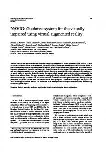
Our system has been designed as a stack of components, each capable of working independently to carry out their corresponding task. Figure 1 is a pictorial representation of the architecture:
Figure 1. Components and architecture of our system.
independently and react to events that would occur throughout the system. The frame-buffer component’s sole responsibility was to always keep a frame of data at hand and always keep it up to date. Any other layer requesting a frame of data would immediately get that frame in hand, instead of forcing the frame buffer component to retrieve a new frame every time it was asked for one. A sample of the frame available from Microsoft Kinect is given in Figure 2.
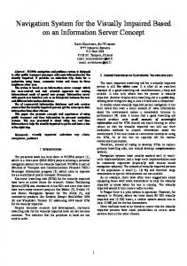
Figure 2. Two types of frames available from the frame buffer. 2.2 Object Classification Frames of data collected from the frame buffer are passed through a few cascades of object recognizer. Each of these cascades is trained to recognize different types of objects in general. The training phase involved the use of standard high definition video camera. The video was then turned into a sequence of images in which a subset was picked out and marked entirely by hand the locations of various objects in the scene. After a phase of Haar-training [13], the cascades were ready. Our initial attempt included two cascades: for chairs and faces. The cascades, being independent of each other, give the advantage of modularity and the possibility of easily extending the system to support even more objects in the future. During the detection of the objects, the classifier module tries to mark regions of interest on the image and tag them with the names of possible class of objects found in those regions. The depth frame, as received from the frame-buffer at that point, is also marked with appropriate tags so that the next step, where more detailed information is determined can use those data quickly to find the regions of interest and their properties. In Figure 3, one frame containing a human face detected correctly is depicted.
These components are discussed in following sections. 2.1 Data Acquisition Kinect being a proprietary technology does not provide unrestricted access to its hardware. However, there is array of device driver to choose from. We chose an open source (OpenKinect [12]) driver to get the maximum insight into how this device works. With some driver interaction and little concurrency techniques, we were able to prepare the framework outlined above where each layer worked almost independently of each other but in a coherent fashion. To be able to adapt to various hardware without overwhelming the underlying system, we used an event driven mechanism. Instead of putting a pressure on the system to deliver frames of data as fast as possible, each component would run
ISBN: 978-988-19252-5-1 ISSN: 2078-0958 (Print); ISSN: 2078-0966 (Online)
Figure 3. Depth frame (Left: raw; Right: regions of interests marked). Since we know which cascade was responsible for the detection and marking of each regions of interest, it is easy to classify those regions as either objects or faces. Furthermore, two specific calculations are performed within this same component as they are common to every region of interest.
IMECS 2014
Proceedings of the International MultiConference of Engineers and Computer Scientists 2014 Vol I, IMECS 2014, March 12 - 14, 2014, Hong Kong
They are distance and angles of the region of interests from the geometric center of the point of view. Every detected object in the system is annotated with a tuple of two values: the approximate distance between the object and the sensor and the angle the object makes with the z-axis of the sensor. These values are calculated using the positional information provided by the object detector and the depth data obtained from the Kinect. Now, the challenge is to get the correct distance of the located object. We cannot just depend on the exact pixel coordinate of the detected object location to find out the distance. Kinect usually measures the distance using its infrared camera. Using this camera for each and every pixel located in the 2D image provides the distance measure in a specified unit. Now, this may be a case that for some pixels which fail to extract the distance value due to some environmental problem and provide a built in zero value in those pixels. Therefore, for the accurate extraction of the distance value, we have followed an algorithm which will not be affected by the environmental problem that may lead to an invalid distance measure. The main idea of the algorithm is to take chunk of area of pixels dynamically around the detected object and find out the median of distances. The algorithms are stated below. 2.2.1
Determining Distance
Median Finding Algorithm One of the most naive way of finding the median of a collection of integers is the following algorithm: 1 2 3 4 5 6
def median(arr): arr.sort() if len(arr) % 2 == 0: return (arr[len(a)/2‐1] + arr[len(a)/2])/2 else: return arr[len(a)/2]
This algorithm runs on a time complexity of O(n log n), due to the sort step of sorting the array. However, as the values of the array elements are in the range [0, 255], we can simply take advantage of a variation of the counting sort algorithm: 1 2 3 4 5 6 7 8 9
def median(arr): counts = [0] * 256 for v in arr: ++counts[v] tmp = 0 for I, v in enumerate(counts): tmp += v if tmp >= len(arr)/2: return v
This algorithm runs on a time complexity of O(n) which is slightly faster than the traditional approach.
2.2.2 Determining Angular Displacement The object detector is capable of providing coordinates in terms of pixels, considering the center of the image to be the origin. These coordinates in pixels were then converted to absolute distance in meters using a linear scaling followed by the use of Pythagoras formula. The coefficients of the linear scaling formula were determined experimentally: The long wooden stick, 1 meter in length was placed 3 meters away from the camera. The number of pixel it covered in the image was measured. The coefficients were then computed from the available information. This process was repeated by keeping the stick at 4, 5 and 6 meters distances to ensure that the linear scaling was effective enough and that such subtle change in the distance did not have any significant effect on the accuracy of the scaling process. This gave us the distance of the object on the xy-plane. The sensor provides depth information in a non-standard unit. According to its specification, Kinect is capable of determining distance ranging between 2 and 7 meters. The depth value, as provided by the device drivers, ranges between 0 and 255. The distance was calculated by multiplying a constant factor with the depth value provided by the driver. The constant factor was initially set to 0.027 which maps a value of 0 to 2 meters and a value of 256 to 7 meters. Although this gave pretty close results for most cases, it was later adjusted a little bit to counter the inaccuracy of the device itself. The final value of the constant factor was determined through trial and error. With these data combined, the angle between the object and the z-axis was computed by finding cos inverse of the ratio of the two distances: the absolute distance and the distance between the origin and the projection of the object on xy-plane. 2.2.3 Chair detection A Logitech HD Camera has been used to take video shoot of the concerned object in various environments. The reason behind taking high definition video shoot is to capture maximum details of an object in real environment. For all type of objects, we tracked them in different shape and environment and took 360 degree video shoot each time for one minute. As our system was tested in our university campus, our prime focus was to shoot video of different backgrounds (negative samples) and store into our system. After that, all those videos were separated into thousands of frames. After this stage, we successfully gathered huge number of images of different objects from various angles in different scenarios. For training, each object had to be identified and marked manually in the images. Out of the thousands of images, we took a large sample of few hundreds and marked them manually. For convenience, a small tool was created that would show each image in sequence and took the markings using a GUI and then stored in a description file. Some sample images are given in Figure 4.
ISBN: 978-988-19252-5-1 ISSN: 2078-0958 (Print); ISSN: 2078-0966 (Online)
IMECS 2014
Proceedings of the International MultiConference of Engineers and Computer Scientists 2014 Vol I, IMECS 2014, March 12 - 14, 2014, Hong Kong
2.2.5 Text Recognition
Figure 4. Marked images and relevant description file output.
The training phase of the system runs for a large amount of time. The end result is the aforementioned cascade file which is then easily loaded into our system. The vector file, from which the cascades are trained, was inspected to see some of the examples of how the training system is perceiving the data. A few such example images are given in Figure 5.
Figure 5. Images from vector file.
For text recognition, we rely on the open source tools called Tesseract [11]. However, the obstacle that we really have to overcome to ensure a good text extraction mechanism involved the fact that the images containing text being fed to Tesseract will be completely arbitrary. Tesseract is optimized to extract text from well format and well scanned document images. The system, on the other hand, will only receive images from a Kinect device and those images may contain text in virtually any form. During the preprocessing stage, our goal was to eliminate the effects of the background and noises on the image as much as possible. This involved applying a series of filters (sharpening, monochrome etc) to the image to reduce such unwanted elements and made the text as vivid as possible. The end result would be an image where the background was almost eliminated and the text would remain as a thin skeletal wireframe. Since this would work only for large texts in the image and that would cover basically all signboards and markers, the compromise was worthwhile. Once the image was passed through the Tesseract, the recognized text was then passed through another small snippet of code which resolved some unexpected character issues. For example, it replaced all '$' signs appearing next to characters (other than digits) into the English character’s’. The text was further spell checked and common errors were fixed. This made the end result much more readable and hence easier for the text to audio engine to processes it better. In Figure 6, we provide a sample notice at the library processed by our system.
2.2.4 Face Recognition In face recognition, it is well known that the likelihood of having noise in the input is very high. In fact, noises caused by variation in lighting, pose etc is very common. Yet, every face bears some features that are quite unaffected by such variations and noises. For example, objects such as eyes, nose, ears and their relative distances. These features can be extracted quite easily using principle component analysis. The first obstacle of such a process is acquiring the images and preprocessing them. However, as that is not a part of our focus in this experiment, the set of images obtained here are already preprocessed to requirement. The second task of this approach in face recognition is to generate the eigenfaces of these images. The eigenfaces are a set of eigenvectors that are used to represent the features of the set of known faces. The approach of using eigenfaces for recognition was developed by Sirovich and Kirby (1987) [14]. The eigenfaces generation process mainly involves performing principal component analysis on the sample data. The process performed on the testing data is similar to the previous process but is slightly different in terms of what is used to normalize the data and also the eigenface used is the one that had already been generated in the previous step. The experiment was repeated several times with slight variation in algorithm constants especially the constant that defines the precision of the eigenface, that is the number of eigenface vectors used in those of the aforementioned steps of the process.
ISBN: 978-988-19252-5-1 ISSN: 2078-0958 (Print); ISSN: 2078-0966 (Online)
Figure 6.Image preprocessing for text recognition. 2.3 Feedback The output unit is the least complex unit of the whole system. It is comprised of a python program that actually works on the text that is supplied by our central processing unit. As we know earlier, the central processing unit actually uses the object classifiers and marks the object in the image frame. After that, the processing unit performs other calculations, sorts out the distance and location of the desired object and formulates a text describing the information. This text works like the input of the output unit. The output unit processes this text using a python
IMECS 2014
Proceedings of the International MultiConference of Engineers and Computer Scientists 2014 Vol I, IMECS 2014, March 12 - 14, 2014, Hong Kong
package named “ESpeak” [15]. “ESpeak” is a voice synthesizer. It converts the text to speech. Therefore, the output unit gets the formulated text after object detection and location determination from the central processing unit which then converts the text to speech using “ESpeak” and deliver to the user.
III.
PERFORMANCE EVALUATION
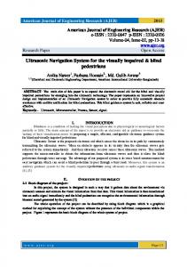
Performance of the proposed system is evaluated from two view points: offline performance and online performance (real-time performance). 3.1 Offline Performance Evaluation 3.1.1 Offline Face Detection Accuracy The performance analysis of offline face detection was evaluated using three different datasets: PIE [16], UMIST [17] and CBCL [18]. Each dataset contains around a thousand facial images, cropped to facial region only and there are slight variations in angle of image acquiring in those images. The following chart (Figure 7) shows the number of true positives, false negatives and false positives for each dataset. The total height represents the actual size of the each dataset.
Figure 8. Error in distance calculation using data from depth map (Lower is better). 3.1.3 Offline Face Recognition Accuracy Face recognition was performed using a small number of subjects. For each subject, around 50 images were captured. The number of images used to train was varied and the performance was measured. Figure 9 shows the face recognition accuracies with various training data sizes.
Figure 9. Face recognition accuracy with varying size of training data. 3.2 Online or Real-time Performance Evaluation
Figure 7. Performance with various datasets. 3.1.2 Offline Distance & Angle Calculation Accuracy The distance measured used data obtained using the depth map of Kinect. Since the distance calculation formula was designed to account for trigonometric approximations, the expected error of the formula was supposed to be constant. However, due to the error inherent in the sensor itself and its depth measuring capabilities, there was an increase in error with increase in distance. Moreover, since the sensor was designed to work only within a short range of distance, distances calculated for objects within the first 2 meters and the distance beyond 9 meters were completely invalid and ignored. Figure 8 shows the average error percentages with various distances. In our experiment, the values for Mean & Median are the same. As such, the lines plotted for Mean & Median overlap each other.
ISBN: 978-988-19252-5-1 ISSN: 2078-0958 (Print); ISSN: 2078-0966 (Online)
Since the system performed fairly well in offline tests, we used the same algorithms and approaches in our real-time use with slight optimizations. The performance measure then all came down to how quickly it processed every frame. In table 1, the time required for each major component processing for in a frame is provided. Table 1.Execution time for each component. Configuration Speed (Average) All components
2.25 seconds per frame
Face recognition
1.7 seconds per frame
Text recognition
0.8 seconds per frame
Face and text recognition
1.9 seconds per frame
Object detection
2 seconds per frame
Face recognition and object detection 2.2 seconds per frame
IMECS 2014
Proceedings of the International MultiConference of Engineers and Computer Scientists 2014 Vol I, IMECS 2014, March 12 - 14, 2014, Hong Kong
IV CONCLUSION In conclusion, we come to understand that it is possible to build a system that can come in aid to those who really need it with the available technologies all around us. People with visual impairment, those who are deprived of this very important sensory system, always tend to lead a difficult life. However, with a system such as this, their life can only get better. Our experiment shows that a complex system such as this can be built from a number of existing, stable components. At the same time, we can make it run efficiently using limited resources. In our experiment, the whole system had been built upon several very simple principles. It was structured in a modular way for greater extensibility. Each chosen component was lightweight and open source for better availability, or was implemented customized to suit our needs. It was independent which reduced the number of articulation points of failure. Overall, the whole system was just one simple pipeline of processing techniques that started from two simple frames of data (rgb and depth) and ended at the generation of audio feedback. At the end of the experiment, although we had a stable and efficient system, there was a considerable number of areas where it could be improved even more especially in terms of accuracy of some of the components. For example, object detection could be improved by employing a better training dataset and spending much more time in the training phase, tweaking the system to reach optimal performance quality.
[13] Open Source Computer Vision Harr training. http://opencv.org/ http://docs.opencv.org/doc/user_guide/ug_traincascade.html [14] L. Sirovich and M. Kirby (1987). "Low-dimensional procedure for the characterization of human faces". Journal of the Optical Society of America, pp. 519-524 [15] ESpeak – A Voice Synthesizer. http://espeak.sourceforge.net/docindex.html [16] The CMU Multi-PIE Face Database. http://www.multipie.org/ [17] The Shefield ( previously UMIST ) Face Database. http://www.shef.ac.uk/eee/research/iel/research/face [18] MIT Center for Biological and Computational Learning Face Database. http://cbcl.mit.edu/software-datasets/FaceData2.html
REFERENCES [1] A. Opelt, M. Fussenegger, A. Pinz, and P. Auer. W eak hypotheses and boosting for generic object detection and recognition. In Proceedings of ECCV 2004. [2] D. G. Lowe. Object recognition from local scale-invariant features. In IEEE Transactions on Pattern Analysis and Machine Intelligence, volume 2, pages 1150 –1157, 1999. [3] R. Fergus, P. Perona, and A. Zisserman. Object class recognition by unsupervised scale-invariant learning. In Proceedings of Computer Vision and Pattern Recognition, volume 2, pages 264–271, 2003. [4] S.Mahamud,M. Hebert, and J. Shi. Object recognition using boosted discriminants. In Proceedings of Computer Vision and Pattern Recognition, volume 1, pages 551–558, 2001. [5] P. Viola, M. Jones. Rapid Object Detection using Boosted Cascade of Simple Features. In Proceedings of Conference on Computer Vision and Pattern Recognition, 2009. [6] S. Sclaroff and A. Pentland. Modal Matching for Correspondence and Recognition. In IEEE Transactions. Pattern Analysis and Machine Intelligence, vol 17,no. 6,pp. 545-561, 1995. [7] G. Scott and H. Longuet-Higgins. An Algorithm for Associating the Features of Two Images. In proceedings of Royal Soc. London, vol. 244,pp. 21-26, 1991. [8] L.S. Shapiro and J.M. Brady. Feature-Based Correspondence: An Eigenvector Approach. Image and Vision Computing, vol. 10, no. 5, pp. 283-288, 1992. [9] S. Umeyama. An Eigendecomposition Approach to Weighted Graph Matching Problems. IEEE Trans. Pattern Analysis and Machine Intelligence, vol. 10, no. 1,pp. 71-96, 1991. [10] M. A. Turk, A. P. Pentland. Face Recognition Using Eigenfaces. [11] Tesseract open source OCR engine. http://code.google.com/p/tesseract-ocr/ [12] Open source OpenKinect project. http://openkinect.org/wiki/Main_Page
ISBN: 978-988-19252-5-1 ISSN: 2078-0958 (Print); ISSN: 2078-0966 (Online)
IMECS 2014