Morgan Kaufmann, Pubs. August 1998. [15] William E. Johnston, W. Greiman, ... [20] Vern Paxson, private communication. [21] J. Semke, J. Mahdavi, M. Mathis, ...
A Network-Aware Distributed Storage Cache for Data Intensive Environments1 Brian L. Tierney, Jason Lee, Brian Crowley, Mason Holding Computing Sciences Directorate Lawrence Berkeley National Laboratory University of California, Berkeley, CA, 94720 Jeremy Hylton, Fred L. Drake, Jr. Corporation for National Research Initiatives, Reston, VA 20191
such data streams. The result will be to make both the data and its analysis much more readily available. For example, health care imaging systems illustrate the need for both high data rates and real-time cataloging. Medical video and image data used for diagnostic purposes — e.g., X-ray CT, MRI, and cardio-angiography — are collected at centralized facilities and may be accessed at locations other than the point of collection (e.g., the hospitals of the referring physicians). A second example is high energy physics experiments, which generate high rates and massive volumes of data that must be processed and archived in real time. This data must also be accessible to large scientific collaborations — typically hundreds of investigators at dozens of institutions around the world. In this paper we will describe how “Computational Grid” environments can be used to help with these types of applications, and how a high-speed network cache is a particularly important component in a data intensive grid architecture. We describe our implementation of a network cache, how we have made it “network aware,” and how we adapt its operation to current network conditions.
Abstract Modern scientific computing involves organizing, moving, visualizing, and analyzing massive amounts of data at multiple sites around the world. The technologies, the middleware services, and the architectures that are used to build useful high-speed, wide area distributed systems, constitute the field of data intensive computing. In this paper we will describe an architecture for data intensive applications where we use a high-speed distributed data cache as a common element for all of the sources and sinks of data. This cache-based approach provides standard interfaces to a large, application-oriented, distributed, on-line, transient storage system. We describe our implementation of this cache, how we have made it “network aware,” and how we do dynamic load balancing based on the current network conditions. We also show large increases in application throughput by access to knowledge of the network conditions.
1.0 Introduction
2.0 Data Intensive Grids
High-speed data streams resulting from the operation of on-line instruments and imaging systems are a staple of modern scientific, health care, and intelligence environments. The advent of high-speed networks is providing the potential for new approaches to the collection, organization, storage, analysis, visualization, and distribution of the large-data-objects that result from
The integration of the various technological approaches being used to address the problem of integrated use of dispersed resources is frequently called a “grid,” or a computational grid — a name arising by analogy with the grid that supplies ubiquitous access to electric power. See, e.g., [10]. Basic grid services are those that locate, allocate, coordinate, utilize, and provide for human interaction with
1. The work described in this paper is supported by DARPA, Information Technology Office (http://www.darpa.mil/ito/Research Areas.html) and the U. S. Dept. of Energy, Office of Science, Office of Computational and Technology Research, Mathematical, Information, and Computational Sciences Division (http://www.er.doe.gov/production/octr/mics/index.html), under contract DE-AC03-76SF00098 with the University of California. This is report no. LBNL-42896.
1
the various resources that actually perform useful functions. Grids are built from collections of primarily independent services. The essential aspect of grid services is that they are uniformly available throughout the distributed environment of the grid. Services may be grouped into integrated sets of services, sometimes called “middleware.” Current grid tools include Globus [8], Legion [16], SRB [3], and workbench systems like Habanero [11] and WebFlow [2]. From the application’s point of view, the Grid is a collection of middleware services that provide applications with a uniform view of distributed resource components and the mechanisms for assembling them into systems. From the middleware systems points of view, the Grid is a standardized set of basic services providing scheduling, resource discovery, global data directories, security, communication services, etc. However, from the Grid implementor’s point of view, these services result from and must interact with a heterogeneous set of capabilities, and frequently involve “drilling” down through the various layers of the computing and communications infrastructure.
Parallel computation / data analysis
Data Source ( instrument or simulation)
processing application scratch data cache partition partition large, high-speed network cache
real-time data cache partition
visualization applications
data cataloguing, archiving, and access control system
tertiaray storage system Disk Storage
Figure 1
Tape Storage
The Data Handling Model
slower tertiary storage system. The cache also provides an “impedance matching” function between a small number of high throughput streams to a larger number of lower speed streams, e.g. between fine-grained accesses by many applications and the coarse-grained nature of a few parallel tape drives in the tertiary storage system. Depending on the size of the cache relative to the objects of interest, the tertiary storage system management may only involve moving partial objects to the cache. In other words, the cache may contain a moving window for an extremely large off-line object/data set. Generally, the cache storage configuration is large (e.g., 100s of gigabytes) compared to the available disks of a typical computing environment (e.g., 10s of gigabytes), and very large compared to any single disk (e.g. hundreds of ~10 gigabytes).
2.1 Architecture for Data Intensive Environments Our model is to use a high-speed distributed data storage cache as a common element for all of the sources and sinks of data involved in high-performance data systems. We use the term “cache” to mean storage that is faster than typical local disk, and temporary in nature. This cache-based approach provides standard interfaces to a large, application-oriented, distributed, on-line, transient storage system. Each data source deposits its data in the cache, and each data consumer takes data from the cache, often writing the processed data back to the cache. A tertiary storage system manager migrates data to and from the cache at various stages of processing. (See Figur e1.) We have used this model for data handling systems for high energy physics data and for medical imaging data. For more information see [15] and [14]. The high-speed cache serves several roles in this environment. It provides a standard high data rate interface for high-speed access by data sources, processing resources, mass storage systems (MSS), and user interface / data visualization elements. It provides the functionality of a single very large, random access, block-oriented I/O device (i.e., a “virtual disk”). It serves to isolate the application from tertiary storage systems and instrument data sources, helping eliminate contention for those resources This cache can be used as a large buffer, able to absorb data from a high rate data source and then to forward it to a
2.2 Network-Aware Applications In order to efficiently use high-speed wide area networks, applications will need to be “network-aware”[6]. Network-aware applications attempt to adjust their demands in response to changes in resource availability. For example, emerging QoS services will allow network-aware applications to participate in resource management, so that network resources are applied in a way that is most effective for the applications. Services with a QoS assurance are likely to be more expensive than best-effort services, so applications may prefer to adjust rather than pay a higher price. Network-aware applications will require a general-purpose service that provides information about the past, current, and future state of all the network links that it wishes to use. Our monitoring system, described below, is a first step in providing this service.
2
3.0 The Distributed-Parallel Storage System from other DPSS servers
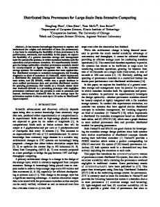
Our implementation of this high-speed, distributed cache is called the Distributed-Parallel Storage System (DPSS) [7]. LBNL designed and implemented the DPSS as part of the DARPA MAGIC project [18], and as part of the U.S. Department of Energy’s high-speed distributed computing program. This technology has been successful in providing an economical, high-performance, widely distributed, and highly scalable architecture for caching large amounts of data that can potentially be used by many different users. Typical DPSS implementations consist of several low-cost workstations as DPSS block servers, each with several disk controllers, and several disks on each controller. A four-server DPSS with a capacity of one Terabyte (costing about $80K in mid-1999) can thus produce throughputs of over 50 MBytes/sec by providing parallel access to 20-30 disks. Other papers describing the DPSS in more detail include [23], which describes how the DPSS was used to provide high-speed access to remote data for a terrain visualization application, [24], which describes the basic architecture and implementation, and [25], which describes how the instrumentation abilities in the DPSS were used to help track down a wide area network problem. This paper focuses on how we were able to greatly improve total throughput to applications by making the DPSS “network aware.” The application interface to the DPSS cache supports a variety of I/O semantics, including Unix-like I/O semantics through an easy to use client API library (e.g. dpssOpen(), dpssRead(), dpssWrite(), dpssLSeek(), dpssClose()). The data layout on the disks is completely up to the application, and the usual strategy for sequential reading applications is to write the data “round-robin,” striping blocks of data across the servers. The client library also includes a flexible data replication ability, allowing for multiple levels of fault tolerance. The DPSS client library is multi-threaded, where the number of client threads is equal to the number of DPSS servers. Therefore the speed of the client scales with the speed of the server, assuming the client host is powerful enough. The internal architecture of the DPSS is illustrated in Figur e2. Requests for blocks of data are sent from the client to the “DPSS master” process, which determines which “DPSS block servers” the blocks are located on, and forwards the requests to the appropriate servers. The server then sends the block directly back to the client. Servers may be anywhere in the network: there is no assumption that they are all at the same location, or even the same city. DPSS performance, as measured by total throughput, is optimized for a relatively smaller number (a few thousand)
er rs oth ve to ser S S DP
Client Application
DPSS Master
to other clients Block Request Thread
DPSS Data Server
Block Writer Thread
*
Shared Memory Cache
Disk Read Thread
Disk Read Thread
Disk Read Thread
Disk Read Thread
Disk
Disk
Disk
Disk
Figure 2: DPSS Architecture of relatively large files (greater than 50 MB). Performance is the same for any file sizes greater than 50 MB. We have also shown that performance scales well with the number of clients, up to at least 64 clients. For example, if the DPSS system is configured to provide 50 MB/sec to 1 client, it can provide 1 MB/sec to each of 50 simultaneous clients. The DPSS master host starts to run out of resources with more than 64 clients. Because of the threaded nature of the DPSS server, a server scales linearly with the number of disks, up to the network limit of the host (possibly limited by the network card or the CPU). The total DPSS system throughput scales linearly with the number of servers, up to at least 10 servers. The DPSS provides several important and unique capabilities for data intensive distributed computing environments. It provides application-specific interfaces to an extremely large space of logical blocks; it offers the ability to build large, high-performance storage systems from inexpensive commodity components; and it offers the ability to increase performance by increasing the number of parallel disk servers. DPSS data blocks are available to clients immediately as they are placed into the cache. It is not necessary to wait until the entire file has been transferred before requesting data. This is particularly useful to clients requesting data from a tape archive. As the file moves from tape to the DPSS cache, the blocks in the cache are immediately available to the client. If a block is not available, the application can either block, waiting for the data to arrive, or continue to request other blocks of data which may be ready to read. The DPSS is dynamically reconfigurable, allowing one to add or remove servers or disks on the fly. This is done by storing the DPSS hardware resource information in a Globus Metacomputing Directory Service (MDS)[5] formatted LDAP database, which may be updated
3
There are several open issues involved in obtaining accurate network throughput and latency measures. One issue is that the use of past performance data to predict the future may be of limited utility. Another issue is whether to use active or passive measurement techniques. Network information such as available bandwidth varies dynamically due to changing traffic and often cannot be measured accurately. As a result, characterizing the network with a single number can be misleading. The measured bandwidth availability might appear to be stable based on measurements every 10 minutes, but might actually be very bursty; this burstiness might only be noticed if measurements are made every few seconds. These issues are described in more detail in [17] and [27]. We plan to adopt techniques used in other projects such as NWS, once they are proven to be sound.
dynamically. Software agents are used to monitor network, host, and disk availability and load, storing this information into the LDAP database as well. This information can then be used for fault tolerance and load balancing. We describe this load balancing facility in more detail below.
4.0 Network-Aware Adaptation For the DPSS cache to be effective in a wide area network environment, it must have sufficient knowledge of the network to adjust for a wide range of network performance conditions and sufficient adaptability to be able to dynamically reconfigure itself in the face of congestion and component failure.
4.1 Monitoring System We have developed a software agent architecture for distributed system monitoring and management. We call this system Java Agents for Monitoring and Management (JAMM) [13]. The agents, whose implementation is based on Java and RMI, can be used to launch a wide range of system and network monitoring tools, extract their results, and publish them into an LDAP database. These agents can securely start any monitoring program on any host and manage the output of any monitoring data. For example, we use the agents to run netperf [19] and ping for network monitoring, vmstat and uptime for host monitoring, and xntpdc for host clock synchronization monitoring. These results are uploaded to an LDAP database at regular intervals, typically every few minutes, for easy access by any process in the system. We run these agents on every host in a distributed system, including the client host, so that we can learn about the network path between the client and any server.
4.3 Load Balancing The DPSS can perform load balancing if the data blocks are replicated on multiple servers. The DPSS master uses status information in the LDAP database to determine how to forward a client's block request to the server that will give the fastest response. A minimum cost flow algorithm [1][9] is used by the DPSS master to optimize the assignment of block requests to servers. Our approach is to treat load balancing as a combinatorial problem. There is some number of clients and servers. Each client must be assigned to one or more servers without any server being overloaded. The minimum cost flow approach is a good match for the combinatorial nature of the problem, but there are several practical challenges to overcome. In particular, the minimum cost flow algorithm is an offline algorithm; the number of blocks each client will request must be know in advance in order to generate a flow of blocks from servers to clients for a given period. However, client arrivals and departures are unpredictable, and for some clients, the request rate and the amount of data requested is also variable. Our solution is to run the algorithm each time a client request arrives, using the actual request for the current client and estimates for every other client. The algorithm itself is fast (less than 1 ms for typical graphs), so this solution is workable. We model the DPSS load balancing problem as a transportation problem [1] (p. 99). Each server has a supply of blocks that must be delivered to the clients. The network is represented as a bipartite graph, where each node is a client or server and each edge is a network path from server to client. Each edge has a per-block cost and a maximum capacity. The algorithm finds a flow of blocks from servers to clients that minimizes the total cost. It is defined for a balanced network, where the total demand is equal to the
4.2 TCP Receive Buffers The DPSS uses the TCP protocol for data transfers. For TCP to perform well over high-speeds networks, it is critical that there be enough buffer space for the congestion control algorithms to work correctly [12]. Proper buffer size is a function of the network bandwidth-delay product, but because bandwidth-delay products in the Internet can span 4-5 orders of magnitude, it is impossible to configure the default TCP parameters on a host to be optimal for all connections [21]. To solve this problem, the DPSS client library automatically determines the bandwidth-delay product for each connection to a DPSS server and sets the TCP buffer size to the optimal value. The bandwidth and delay of each link are obtained from the agent monitoring results which are stored in the LDAP database.
4
based on data from LDAP. We use the CS2 [4] minimum cost flow solver. For a particular request, the solver determines what proportion of the blocks will be delivered by each server. Each block must be looked up in the block database to determine which specific servers it is loaded on. A stride scheduler [26] chooses one of the available servers based on the proportions assigned by the solver.
total supply. For the DPSS, this situation occurs only when the clients have saturated the servers. To create a balanced problem, we introduce a ghost client and a ghost server that have infinite capacity and high-cost links to other servers and clients, respectively. Supply or demand is assigned to one of the ghosts to create a balanced problem. We assign a cost and capacity based on the assumption that network latency is the dominant factor affecting application performance, so that selecting servers with the lowest latency will maximize application performance. The total latency from a client's request to its receipt of the first tile from a server is affected by three different network paths: the paths from client to master, master to server, and server to client. The master obtains the latencies from these three paths from the LDAP database. The total delay for the edge cost is the sum of the three latencies, the processing delay at the master and server, and the transmission delay of a data block across the link between server and client. Data blocks are large (typically 64KB), so the transmission delay is non-trivial, even across a high-speed network. One limitation of this approach is that the graph does not represent the actual network topology. Several edges in the graph may actually share the same bottleneck link in the real network, but the graph does not capture this information. The minimum cost flow algorithm could accommodate a more detailed model of the network, but the monitoring system only collects information about host-to-host performance. The edge capacity is set to the bandwidth obtained from the LDAP database. This capacity may be reduced based on the degree of replication of the data blocks. When data is loaded into the DPSS, blocks are distributed acros n servers and each block is replicated m times, where m