marking scheme and compare it against the fragment-based. PPM [1]. Simulation results show that for similar bit-budget, our scheme significantly reduces the ...
A Network Coding Approach to IP Traceback Pegah Sattari, Minas Gjoka, Athina Markopoulou University of California, Irvine {psattari, mgjoka, athina}@uci.edu
Abstract—Traceback schemes aim at identifying the source(s) of a sequence of packets and the nodes these packets traversed. This is useful for tracing the sources of high volume traffic, e.g., in Distributed Denial-of-Service (DDoS) attacks. In this paper, we are particularly interested in Probabilistic Packet Marking (PPM) schemes, where intermediate nodes probabilistically mark packets with information about their identity and the receiver uses information from several packets to reconstruct the paths they have traversed. Our work is inspired by two observations. First, PPM is essentially a coupon collector’s problem [1], [2]. Second, the coupon collector’s problem significantly benefits from network coding ideas [3], [4]. Based on these observations, we propose a network coding-based approach (PPM+NC) that marks packets with random linear combinations of router IDs, instead of individual router IDs. We demonstrate its benefits through analysis. We then propose a practical PPM+NC scheme based on the main PPM+NC idea, but also taking into account the limited bit budget in the IP header available for marking and other practical constraints. Simulation results show that our scheme significantly reduces the number of packets needed to reconstruct the attack graph, in both single- and multi-path scenarios, thus increasing the speed of tracing the attack back to its source(s).
I. I NTRODUCTION DDoS attacks are one of the hardest problems on the Internet today [5], during which a large number of compromised hosts coordinate and send unwanted traffic to the victim, thus exhausting its resources and preventing it from serving its legitimate clients. In particular, in bandwidth flooding attacks, a large number of attack flows flood the victim’s access link with unwanted traffic. Several approaches have been proposed to deal with flooding attacks. In this work, we focus on IP traceback schemes, which trace the attack back to its source(s). Traceback in itself does not stop an attack, but it is an important component in a bigger defense system, when combined with additional mechanisms such as intrusion detection or filtering for blocking unwanted traffic. There is a large body of literature on traceback schemes [6]. In this work, we are interested in multi-packet Probabilistic Packet Marking (PPM) schemes, where packets are marked probabilistically with information about the IP addresses of the routers they traverse. The victim then uses this information to reconstruct the router IP addresses, and trace the attack back to its source(s). Early on [1], [2], it was observed that PPM is essentially a coupon collector’s problem. Moreover, the coupon collector’s problem significantly benefits from the network coding idea [3], [4]. Inspired by these observations, we propose the PPM+NC approach. The intuition is that if we mark packets with random linear combinations of the router IDs, instead of individual IDs (as in traditional PPM), the number of packets required to reconstruct the attack paths can be significantly reduced, and the attackers can be traced faster. We implement This work was supported by NSF CAREER award 0747110.
this idea by taking into account the practical constraints and using a limited number of under-utilized bits on the IP packet header for marking. Our practical PPM+NC scheme allocates the bit-budget optimally between the coefficients and the linear combination in the marking field on the IP packet header. There is a large body of literature on PPM, trying to improve the tradeoff between the number of bits used in the IP header and the number of packets required to reconstruct the attack paths [7]. This can be achieved in two ways: (i) through the content of the mark, i.e., reducing the number of bits by using fragments [1] or hashes [8] instead of the entire IP address, or algebraic coding ideas [9]; or (ii) through adjusting the marking probability at each router depending on its position on the path, as in Adjusted PPM (APPM) [10]. In this work, we propose a fragment-based network coding marking scheme and compare it against the fragment-based PPM [1]. Simulation results show that for similar bit-budget, our scheme significantly reduces the number of packets needed for reconstruction, in several attack scenarios. The network coding marking idea is orthogonal to and can also be combined with hashing and APPM to improve the overall performance. The rest of the paper is organized as follows. Section II discusses related work. Section III presents the main idea behind PPM+NC and provides analytical models. Section IV presents the practical PPM+NC scheme based on the main idea, but taking into account the practical constraints. Section V provides simulation results. Section VI concludes the paper. II. R ELATED W ORK There is a large body of literature on IP traceback schemes, as surveyed in [6]. In this work, we focus on multi-packet Probabilistic Packet Marking (PPM) schemes. Savage et al. [1] proposed one of the earliest such schemes, called Fragment Marking Scheme (FMS), taking into account the limited number of bits available for marking on the IP header. FMS divides each router’s IP address and redundancy information into some 8-bit fragments; each router probabilistically marks packets with one of the fragments chosen uniformly at random. FMS is good for single-path attacks, but results in high computation overhead and high false positive rate in distributed attacks [8]. Song et al. [8] proposed an Advanced Marking Scheme (AMS) to improve the computational efficiency and accuracy of reconstructing the attack paths under large scale DDoS. They also have an authentication scheme to deal with spoofing from compromised routers. They assume that a map of upstream routers is available at the victim using the traceroute tool; the goal is then to infer which paths on the map were traversed by the attack traffic. Yaar et al. [11] proposed Fast Internet Traceback (FIT), which is similar to AMS in using the upstream router map and in the packet marking format, but
linear combination
A
d
d-1
Pm(d) Pm(d-1)
3
2
1
Pm(3)
Pm(2)
Pm(1)
V
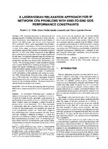
Fig. 1: PPM over a single path with d routers from the attacker to the victim. it obtains the map using the same packet markings that it uses for reconstruction rather than traceroute. FIT also uses a TTL modification technique to store the distance of the marking router in 1 bit only. We utilize their technique in Section IV. Dean et al. [9] proposed an algebraic approach by encoding the information of routers into a polynomial. Adler [7] studied the tradeoff between the number of bits used for marking and the number of packets, and proposed a 1-bit marking scheme. In this paper, our practical PPM+NC scheme is proposed and evaluated using fragmentation [1]. We have also proposed combining network coding with AMS and APPM in [12]. III. M AIN I DEA Problem Statement. Consider Fig.1; attacker A sends packets towards the victim V , through a single path of length d. Ideally, we would like every router on the path to append its own IP address on each packet, so that the packet contains the entire path when it arrives at V . Unfortunately, it is infeasible as it requires a large and variable number of bits on the header. The PPM scheme requires space only for one mark on the IP header: each node i along the path makes an independent decision whether to mark a packet with its IP address, with marking probability Pm (i), or not. If it decides to do so, it overwrites any previous mark. Each packet contains at most one router’s mark after traversing the entire path. We call perceived probability the probability that a packet still carries router i’s mark when it arrives at V : Pp (i) = Pm (i) · Qj=i−1 j=1 (1 − Pm (j)). The marks on the packets allow V to sample the routers on the path. The goal of PPM is to enable V to recover d router IDs after receiving a sufficient number of packets, X, where X ≥ d as some marks may be duplicate. The PPM+NC scheme tries to achieve the same goal with a smaller X, by intelligent marking at intermediate nodes. The PPM+NC Approach. Early on [1], [2], it was observed that PPM is essentially a coupon collector’s problem [13]. In the classic problem, all n coupons are obtained with an equal chance of p = n1 . The collector needs to collect a random number of coupons X, which on average is Θ(n ln n) [2], to get the entire collection. However, note that, in PPM, routers overwrite the previous mark on a packet. Thus Pp (i) depends on the distance of node i from V : the further from V , the less likely that the mark will not be overwritten as the packet moves along the path. Thus the coupon collector’s problem with unequal probabilities models PPM more accurately [14]. If Pm (i) = p is the same for all routers, then Pp (i) = p(1 − p)i−1 . If there are d routers on the path, the average number of packets needed to reconstruct the attack path is, [14]: Z ∞ d Y i−1 E[XPPM ] = (1 − (1 − e−p(1−p) x ))dx (1) 0
i=1
Another observation, made in the network coding community [3], [4], [15], is that the network coding idea can reduce
∑ci.IDi
random coefficients
c1 c2
ck
Fig. 2: The marking field on an IP packet header in PPM+NC. IDi is router i’s entire IP address; ci is selected uniformly at random out of F2b . E[X] in the classic coupon collector’s problem from Θ(n ln n) to Θ(n), by storing random linear combinations of coupons instead of the coupons themselves. In fact, as we collect more coupons, it becomes harder to find innovative ones and most of the time is spent on collecting the last few coupons. If each box contains random linear combinations of coupons, instead of individual coupons, we can obtain all n coupons by receiving n independent linear combinations and solving the system. Intuitively, each random combination is more likely to bring some innovative information, thus be more useful. Based on the previous two observations, we propose the PPM+NC scheme that combines random linear network coding [16] with PPM: each router i decides to mark a packet with probability p. Once it decides to do so, it chooses a coefficient ci randomly out of a field F2b , multiplies its IP address IDi with ci , and adds the result to the current content of the marking field. To show the basic idea, we first assume that the IP header has enough space to store the entire 32-bit IP address, or linear combinations of IP addresses. In Section IV, we consider the bit limitations and other practical constraints. Fig.2 shows the part of an IP packet header used for marking: part of the marking field stores a certain number k of coefficients ci , and another part stores the linear combination Pi=k c · ID i , computed over a field of appropriate size Fq . i=1 i q is discussed in Section IV. Our goal is to recover the router IP addresses from the marked packets by solving a system of linear equations, after receiving sufficient innovative packets. We first show the benefit of this approach analytically. In [4], it is proved that with network coding, E[X] = Θ(n) coupons are needed to obtain n linearly independent equations, thus n coupons. E[X] can be made arbitrarily close to n by increasing the field size q: E[X] ∼ = n as q → ∞. But we have an additional parameter p in PPM+NC: each router contributes to the linear combination in a packet with probability p. If p = 1, E[X] will be similar to the analysis in [4]. In practice, p < 1: a packet contains a linear combination of some router IDs because we do not want routers to work too much and we have limited space for marking. We adjust the analytical model by taking p into account; we have: E[X] = Θ(n/p). Proof: Let Xi be the number of packets required to get the ith router ID, assuming that we already have i − 1 router IDs. Xi is a geometric random variable with probability pi = Pm (i)×Pn , where Pn is the probability that the victim receives i−1 an innovative linear combination; thus pi = p.(1 − qqn ). Considering E[Xi ] = p1i and X = Σni=1 Xi , we have: E[X] =
qn 1 1 1 .( n + n + ... + n ) p q q −q q − q n−1
We omit the details due to lack of space, but bounding E[X] above will result in E[X] = Θ( np ). In practice, p is very small and as we later see through simulations in Fig.3, the number of packets required to obtain
A1
A2
A3 A4
A5 A6 A7 A8
R8
R9
R10 R11
R12 R13 R14 R15
250 simulations PPM model PPM simulations PPM+NC model PPM+NC
Average number of packets
200
distance=4
distance=3
distance=2
150
distance=1 100
R4
R5
R6
R2
R7 R3
R1
V 50
0
Fig. 4: An example attack tree, with 15 nodes and 8 attackers flooding the 0
5
10
15 20 Path length
25
30
35
Fig. 3: Simulation and analytical results for the average number of packets required for a single path of varying length d = 1...31, in PPM and PPM+NC. 1 The coefficients are chosen randomly from F22 , p = 25 , 500 realizations.
a full-rank system is much less than n/p. The formula of the unequal coupon collector’s problem [14], as in Eq.(1), but with the proper Pp (i) for PPM+NC, gives a more accurate model for E[X] in PPM+NC. Once a router decides to mark a packet (with prob. p), it will result in an innovative linear combination with high probability. Thus, Pp (i) ∼ = Pm (i) = p, and: Z
∞
E[XPPM+NC ] =
(1 − 0
d Y
(1 − e−px ))dx
(2)
i=1
Fig.3 shows that the models in Eq.(1) and Eq.(2) perfectly agree with the simulation results. It compares PPM+NC to PPM in terms of the average number of packets required to reconstruct the attack path, of length 1 to 31 hops, which is the case for most Internet paths [1]. We select p = 0.04 (∀ routers), because p ≤ d1 minimizes the number of required packets [1], and only a few path lengths exceed 25 hops in the Internet. We see that PPM+NC significantly outperforms PPM, especially for longer attack paths. We also see that PPM+NC requires much less packets than d/p, as previously mentioned. Note that the PPM+NC coefficients are chosen from a small field F22 , as we justify in Section IV. In Fig.3, we assume that the 32-bit IP addresses or their linear combination can be stored on the header. In Section IV, we consider the bit budget and other constraints in our practical PPM+NC scheme. In practice, an attack can be distributed, i.e., several attack sources can flood the victim through different attack paths that eventually form a tree with leaves being the attackers and root being the victim. Fig.4 shows a full binary attack tree. Each packet traverses one of the paths in the tree. In PPM+NC, once a router in the selected path decides to mark the packet, it acts similarly to the single-path scenario. This marking procedure affects the reconstruction, as we discuss in Section IV-C. We assume that: (i) attackers may send any packet; (ii) they may be aware of traceback; (iii) they send numerous packets; (iv) multiple attackers may act together; (v) routes between hosts are fairly stable; (vi) routers are not compromised. IV. P RACTICAL PPM+NC S CHEME A. Practical Constraints Section III described the PPM+NC idea. To design a practical PPM+NC scheme, we consider the following constraints:
i=8 victim V . {Ri }i=15 i=1 represent the routers and {Ai }i=1 represent the attack sources. The tree consists of 8 paths, each from one {Ai } to V . Each attack packet comes from one possible {Ai } and reaches V through an attack path, i.e., the ordered list of routers between {Ai } and V that the packet traverses.
I. Bit budget. The most important constraint is the number of bits on the IP header available for marking. Typically, traceback schemes use some, currently under-utilized, bits on the header: at least the 16 bits of the IP identification field [1], or at most 25 bits (also including the 8-bit TOS field and the unused fragment flag) [9]. Obviously, the main PPM+NC idea of Section III, which marks with linear combinations of the entire 32-bit IP addresses, will not work under this constraint: even a single IP addressP does not fit within the bit budget, let i=k alone their combination i=1 ci · IDi , and the coefficients ci . To deal with the bit limitation, each router may encode only partial information about its IP address, using fragmentation [1] or hashing [8]. In fact, important information in each mark (thus the number of required packets) is traded-off for reduced number of bits. We divide a router’s 32-bit IP address into f fragments, each of size d 32 f e bits, and construct linear combinations of the fragments instead of the entire addresses, of size also d 32 f e bits. We also need dlog2 f e bits for the fragment offset (to indicate which fragment we use): once a router picks a fragment, the subsequent marking routers pick the same fragment; the victim learns the fragment offset by looking at the mark. We store k random coefficients, each selected randomly out of F2b , thus requiring b bits. We also use a distance field (distance), to indicate the distance of the mark from the victim. It is typically of 5 bits, to represent maximum Internet path lengths of 31 hops [1]. However, using the technique in [11], we can have a 1-bit distance only. f, b, k need to be chosen such that the total number of bits fits within our budget and we also achieve fast reconstruction (small X): 32 d e + dlog2 f e + k · b + distance ≤ bit budget (3) f f was also a parameter in previous fragmentation schemes; we use f = 4 fragments, of 8 bits each [1]. k, b are unique to our network coding scheme. b can be small in practice, e.g., b = 2. Note that the linear combination is computed over F28 because of the fragment size. k is a predetermined number of coefficients that can be stored on a packet: we need k = dd·pe to accommodate the average number of marks in the path. In practice, d ≤ 31 and p = 0.04 [1]; we choose k = 3 as we justify in Section IV-B. When all k coefficients are marked, the next routers need to get informed that they have no space to mark, e.g., by initializing the marking field to zero and having routers check whether the coefficient slots are still zero or not.
random linear offset coefficients distance combination
0
0 0
A
Algorithm 1 Practical PPM+NC: Marking at router RL
8 2 2 2 2 cLRLj j cL 0 0 overwrite RL+1
RL
8
2 2 2 2 j cL cL-1 1 add
cLRLj+cL-1RL-1j
0
8 2 2 2 2 cL+1RL+1i i cL+1 0 overwrite
RL-1
V
RL+10.RL+11.RL+12.RL+13 RL0.RL1.RL2.RL3 RL-10.RL-11.RL-12.RL-13
Fig. 5: Practical PPM+NC with 8-bit linear combination, 2-bit offset, k = 3 2-bit coefficients, and 1-bit distance. RL+1 , RL overwrite, RL−1 appends. II. Spoofing by the Attacker. In practice, an attacker may mark the original packet with a spoofed (erroneous) address to confuse the decoding at the victim. Ideally, we would like the router closest to the attacker to zero out the marking field before adding its value. However, there is no reliable way to determine a router’s location on the path. One solution is to have each marking router overwrite the current mark on the packet, with some probability, thus cancel the forged information. However, since it happens with low probability, some packets might not be marked at all and arrive with their initial marks from the attacker. An additional measure against spoofing is to use a distance field. The idea is to have the routers that overwrite, zero this field and all other routers increment it. This way, we have an indication of a router’s location on the path, which is used in the reconstruction; we also limit the effect of spoofing to the approximate traceback problem1 . We use both techniques in our practical scheme; we combine overwriting with the PPM+NC idea so that each node (i) probabilistically decides to overwrite the previous mark and (ii) increments the distance field regardless of whether it marks or not (unless it overwrites, in which case it zeros the field). III. Identifying Nodes vs. Reconstructing the Attack Graph. In addition to reconstructing the router IP addresses, it is also desirable to reconstruct the order in which they are traversed by the packets, i.e., the attack paths and graph. In multi-path attacks, more information is needed to reconstruct the edges and eventually the attack graph. At an abstract level, the same analysis holds for edge sampling algorithms that mark with edge IDs (XOR of neighboring node IDs) instead of node IDs (router addresses) [1]; the only difference is that the coupon sampled is an edge not a node. At a practical level, we use (i) a distance field and (ii) encoding of consecutive nodes (thus revealing edges) in our practical PPM+NC scheme. These mechanisms provide additional information that helps us reconstruct the attack graph after collecting all IP addresses. B. Marking Procedure We now design a practical PPM+NC scheme that implements the basic idea of Section III, but also takes into account the practical constraints of Section IV-A. We divide each router Ri ’s IP address into 4 fragments: “Ri0 .Ri1 .Ri2 .Ri3 ”, each Rij of 8 bits. We allocate 8 bits to the linear combination of fragments, 2 bits to the fragment offset, and k × b = 6 bits to the coefficients. We use the technique in [11], which re-uses the TTL field in the IP header, to have distance = 1 bit only. We later discuss how this bit allocation is optimal for our scheme. 1 The approximate traceback [1] finds a candidate path that contains the true attack path as a suffix. Spoofed packets will have a distance value greater than or equal to the true attack path length and cannot affect the valid suffix. In distributed attacks, this applies to the packets from the closest attacker only.
1: for each packet P do 2: Pick u uniformly at random from [0, 1] 3: if u < Pm (RL ) then 4: /*decide to overwrite*/ 5: Zero-out all fields, including P.distance := 0 6: Pick cL to be a random coefficient out of F22 7: Pick the j th fragment offset randomly from {0, 1, 2, 3} j 8: Let RL be the corresponding fragment of RL with offset j j 9: Write P.linear combination := cL · RL 10: Write P.offset := j 11: Write cL into the first slot of P.random coefficients 12: else 13: /*decide not to overwrite*/ 14: Increment the distance field P.distance + + 15: if there is space (i.e., zero slot) in P.random coefficients then 16: Read the stored fragment offset P.offset = j j 17: Let RL be the corresponding fragment of RL at that offset 18: Pick cL to be a random coefficient out of F22 19: Write cL in the first available slot of P.random coefficients j 20: Update P.linear combination+ = cL · RL 21: end if 22: end if 23: end for
Let us call these fields of the packet P : P.linear combination, P.offset, P.random coefficients, and P.distance respectively. We need 17 bits in total, which is still within the bit budget (the 16-bit IP ID field and the 1-bit fragment flag [9]). Alg. 1 summarizes the marking scheme. Initially, the marking field of each packet contains all zeros (unless spoofed to some other value). When the packet arrives at the victim, it contains the linear combination of up to k = 3 consecutive router IP addresses. Fig.5 shows an example: the first router, RL+1 , decides with probability Pm (RL+1 ) whether to overwrite the previous mark on the packet. Assume that it decides to do so. First, it zeros out the entire marking field, including distance, then: (i) it picks a random coefficient cL+1 and writes it in the first slot available for the coefficients; (ii) it i picks the ith fragment of its IP address, RL+1 , and writes the i offset i; and (iii) it writes the linear combination cL+1 · RL+1 . The next router, RL , also decides to overwrite: it zeros the j entire field and writes its own values cL , j, and cL · RL . The third router, RL−1 , decides not to overwrite: it checks for empty slots in the vector of random coefficients. If there is space, e.g., in this example, then: (i) it reads the offset j set by j the previous router and picks its own j th segment RL−1 ; (ii) it picks a random coefficient cL−1 and writes it in the first zero slot; and (iii) it adds its information to the linear combination j j by updating it to cL · RL + cL−1 · RL−1 (computed in F28 ). If there were no space (all 3 coefficients were non-zero), it would not mark at all. In any case, a router that does not overwrite always increments the distance field. Note that once a router decides to overwrite and mark, the two next consecutive nodes must also mark unless no more routers exists on the path. The distance field helps to reconstruct the attack graph, by telling the victim from how far away the packet is marked, and also to minimize spoofing. If the mark was from any (not consecutive) three nodes, we would need 3 distance values for reconstruction, which is not space-efficient. Consecutive marks require the distance from the last overwriting node (RL ) only. The other distances (RL−1 ,RL−2 ) differ by 1 and 2 from that.
Bit budget 16 Bit budget 17 Bit budget 18 Bit budget 19 Bit budget 20 Bit budget 21 Bit budget 22 Bit budget 23 Bit budget 24 Bit budget 25
900 800
Average number of packets
700 600 500
j j j c L · RL + cL−1 · RL−1 + cL−2 · RL−2 = P.linear combination (4)
400 300 200 100 0
0
2
4 6 Number of coefficients
8
10
Fig. 6: The effect of k on the performance (the number of required packets) for different bit budgets 16-25. b = 2, d = 14, p =
1 , 25
500 realizations.
Optimal allocation of the bit budget. We now explain how we select f, k in Alg. 1. We need to use the limited bit budget available for marking so as to optimize the following tradeoff. On one hand, we want to store more random coefficients to increase the chances of a packet containing an innovative linear combination: having a large number of marking routers, thus more coefficients, makes it unlikely that all routers pick the exact same coefficient twice in a row, thus two packets be linearly dependent. On the other hand, we want to have larger fragments, thus larger linear combinations; otherwise, we would need to collect many smaller fragments of a single router. Given a limited space, we cannot have both at the same time. We optimize the bit allocation between the 2 parts of the marking field, i.e., the coefficients and the linear combination. Fig.6 shows the effect of increasing k on the performance, 1 for bit budgets 16 to 25. We set d, p, b to 14, 25 , 2 respectively. Consider bit budget 17 (the red curve): we extend the coefficient space by increasing k from 1 to 5. As a result, the space for the linear combination reduces from 14 to 6 bits.2 We observe that the number of packets initially decreases, because of the “longer”/innovative linear combinations received from each packet. However, after some point, the innovative combinations no longer help; the effect of the larger number of smaller fragments we need to collect becomes dominant, and makes the number of packets increase. There is always an optimal k that minimizes the number of packets. For bit budget 17, it is k = 3, which justifies our selection. For all bit budgets, practical PPM+NC always needs a relatively small k. C. Reconstruction Procedure After collecting sufficient marked packets, the victim needs to infer the IP addresses of routers traversed by the packets, as well as the attack paths formed by the routers (connecting the attackers to V ). We describe the procedure under 2 scenarios: 1) Single-path attack: In this case, e.g., Fig.1,5, we can use a simple algorithm. Each packet P , marked by a triplet of consecutive routers, RL , RL−1 , RL−2 , contains: P.linear combination (the linear combination of 3 fragments); P.random coefficients = (cL , cL−1 , cL−2 ); P.offset = j (the same fragment offset for all routers); and P.distance = L (the distance from the last overwriting router (RL ) to V ). Once the victim receives P , it forms the following linear equation: 2 There is another tradeoff in the number of bits allocated to the linear combination vs. those allocated to the offset. When less bits are used for the linear combination, the fragments become smaller and the offset size increases.
The unknowns in Eq.(4) are the j th fragments of the three routers. Eventually, the victim wants to find all fragments of all IP addresses Rij , ∀i = 1...d, j = 1...f . It can do so by solving a linear system after receiving d × f innovative packets. 2) Multi-path attack: This case differs from the single-path attack in that there exist multiple routers at the same distance from the victim; thus the victim needs to differentiate between equations coming from different paths. For example in Fig.4, assume that two packets, both with distance = 4, one marked by R8 , R4 , R2 and the other one marked by R15 , R7 , R3 , arrive at V . The victim cannot decide whether the two marks belong to the same triplet or not. In general, it cannot assign the packet markings in the form of Eq.(4), i.e., packets with distance = L, to a unique triplet of unknowns, as there are several paths with such triplets. We can resolve this ambiguity in two ways. We omit the details due to lack of space, and we only explain the main ideas. Further discussion can be found in [12]. In the first solution, we can use the 8 remaining bits, out of the entire 25 bits available for marking, to store an additional checksum, which helps to identify a triplet of marking routers. E.g., we can have each router pre-compute an 8-bit hash of its IP address. During marking, the overwriting router sets the checksum to its 8-bit hash while each of the consecutive routers XORs the existing checksum value with its 8-bit hash. Assuming there are nt possible triplets at distances L, L − 1, L − 2, 8-bit hashes result in n28t collisions at those distances. The less bits we use, the larger the probability of collision. In the second solution, we can use the standard assumption that the victim has a map of upstream routers [8], [11]. It can be generated before the attack occurs, e.g., using traceroute. The goal is then to identify the attack graph contained in the map (the routers traversed by the attack packets). The victim can use a different technique: once it receives a marked packet, instead of assigning it to a triplet, it looks up the distance value and locates all triplets at this distance in the map. For each candidate triplet, it computes the linear combination of fragments, using the ci ’s and f given in the packet. If the result matches the mark, the routers were indeed traversed by the packet. This procedure does not solve a linear system and starts the reconstruction from the first incoming packet; the more packets received, the more accurate the reconstruction. If a router is added to the attack graph after validating its all f fragments, there will be 2n32t false positive triplets at distances L, L−1, L−2. In both solutions, the frequency of the arriving fragments can also help to further reduce the error as in [11]. D. Processing Costs Our proposal generates more random numbers, not only for the marking decision but also for the coefficient, compared to traditional PPM. However, a random coefficient is needed only when there is space for marking, and a few random numbers can be pre-computed and used for all packets. Each router can compute the linear combination quickly in F28 using a translation (log) table. In the reconstruction, we solve a system of linear equations, or try addresses against a given linear combination. Thus, the benefit of our proposal is at the cost of increased computational complexity and processing time.
Binary tree
5
2500
10
1000
10
Average number of packets
1500
(modified) FMS Practical PPM+NC
(modified) FMS Practical PPM+NC
4
Average number of packets
Average number of packets
2000
Power−law topology
5
10 (modified) FMS Practical PPM+NC
3
10
2
4
10
3
10
10 500
0
1
0
5
10
15 20 Path length
25
30
(a) A single attack path, 1 ≤ d ≤ 31.
35
10
2
0
20
40
60 80 100 Number of nodes in the tree
120
140
(b) Full binary attack trees of 3-127 nodes.
10
10
20
VI. C ONCLUSION AND F UTURE W ORK We proposed a network coding approach to PPM, based on the idea of marking packets with random linear combinations 3 In FMS [1], a mark contains a randomly selected fragment of an edge ID (XOR of neighboring node IDs), its offset, and distance. The size of each node ID, thus edge ID, is doubled to 64 bits by being bit-interleaved with a 32-bit hash of itself. It helps to avoid combining fragments of different edges in multi-path attack reconstruction. Each edge ID has eight 8-bit fragments. 4 In edge-based marking schemes, the distance requires at least 2 bits [11].
40 50 Number of attackers
60
70
80
(c) Power-law attack graph by BRITE.
Fig. 7: Comparison of modified FMS and practical PPM+NC in single- (a) and multi-path (b,c) attacks. p = V. S IMULATION R ESULTS We now compare the practical PPM+NC against the fragment-based PPM without NC, i.e., FMS in [1], in terms of the expected number of packets to be collected, for both single- and multi-path attacks. We first make the comparison fair. FMS uses 16 bits in total: 8 bits for the fragment, 3 bits for its offset, and 5 bits for the distance.3 While practical PPM+NC uses 17 bits, with a 1-bit distance. We take this difference into account by considering a larger fragment size for FMS: we modify FMS such that it uses 17 bits in total, with the TTL-based distance. Note that in multi-path attacks, the checksum technique is used for both FMS and PPM+NC; thus the comparison would still be fair. The modified FMS allocates 2 bits to distance4 , 12 bits to the fragment, and 3 bits to its offset. We collect 6 fragments for each 64-bit address. Fig.7 shows the results. Fig.7(a) shows the comparison of modified FMS and practical PPM+NC in a single-path attack, for different path lengths of 1 to 31. Fig.7(b) compares the two schemes for full binary attack trees with a varying number of nodes (3-127). We also simulated full ternary and m-ary trees, the results were similar. Fig.7(c) shows the results for nonregular attack trees, based on a realistic power-law topology generated by BRITE [17]. We used the router-only mode and the GLP model. Preferential connectivity, incremental growth, and random node placement were selected. The parameter m, which sets the number of links added per new node, was set to 2. We first generated a 150 node graph, extracted a tree out of it with its root being the victim, and tried different numbers of attackers from 15 to 75, located at the leaves. All results are 1 . In all cases, we averaged over 500 realizations and p = 25 observe that for practically the same bit budget, the NC-based scheme significantly reduces the number of packets required for reconstruction. Thus, it can trace the attackers much faster. In multi-path attacks, it performs even better for larger trees.
30
1 , 25
500 realizations.
of router IDs, instead of individual IDs. We implemented this idea considering the bit budget and other practical constraints. Through analysis and simulations, we showed that our scheme significantly reduces the number of packets, in several attack scenarios. The network coding idea can also be combined with and improve other PPM schemes, as it is orthogonal to their contribution (hashing, authentication or adjusted probabilities). We only proposed the basic NC-based PPM in this work. In the future, we plan to: (i) extend our intra-path coding scheme by taking advantage of sliding window protocols, as in TCP, to further improve the reconstruction at the victim; (ii) also perform inter-path coding to further exploit the NC benefits. ACKNOWLEDGMENT We would like to thank Christina Fragouli for discussions on the coupon collector’s problem, which inspired this work. R EFERENCES [1] S. Savage, D. Wetherall, A. Karlin, T. Anderson, “Network support for IP traceback,” In IEEE/ACM ToN, vol. 9, issue 3, pp. 226-237, 2001. [2] M. Mitzenmacher, E. Upfal, “Probability and Computing: Randomized Algorithms and Probabilistic Analysis,” Cambridge Univ. Press, 2005. [3] S. Deb, M. Medard, C. Choute, “Algebraic Gossip: A Network Coding Approach to Optimal Multiple Rumor Mongering,” In IEEE Transactions on Information Theory, vol. 52, issue 6, pp. 2486-2507, 2006. [4] C. Fragouli, E. Soljanin, “Network Coding Applications,” Foundations and Trends in Networking, vol. 2, no. 2, pp. 135-269, 2007. [5] J. Mirkovic, S. Dietrich, D. Dittrich, P. Reiher, “Internet Denial of Service: Attack and Defense Mechanisms,” Prentice Hall, 2004. [6] A. Belenky, N. Ansari, “On IP Traceback,” In IEEE Communications Magazine, vol. 41, issue 7, pp. 142-153, 2003. [7] M. Adler, “Tradeoffs in Probabilistic Packet Marking for IP Traceback,” In Proc. of 34th ACM Symposium on Theory of Computing, 2002. [8] D. X. Song, A. Perrig, “Advanced and Authenticated Marking Schemes for IP Traceback,” In Proc. of IEEE INFOCOM’01, pp. 878-886, 2001. [9] D. Dean, M. Franklin, A. Stubblefield, “An Algebraic Approach to IP Traceback,” In ACM TISSEC, vol. 5, no. 2, pp. 119-137, 2002. [10] T. Peng, C. Leckie, K. Ramamohanarao, “Adjusted Probabilistic Packet Marking for IP Traceback,” In Proc. of IFIP Networking Conf., 2002. [11] A. Yaar, A. Perrig, D. Song, “FIT: Fast Internet Traceback,” In Proc. of IEEE INFOCOM’05, vol. 2, pp. 1395-1406, 2005. [12] P. Sattari, M. Gjoka, A. Markopoulou, “A Network Coding-Based Approach to Probabilistic Packet Marking,” Technical Report Available at: http:// newport.eecs.uci.edu/ ∼psattari/ tracebackReport.pdf , Dec. 2009. [13] P. Erd˜os, A. R´enyi, “On a Classical Problem of Probability Theory,” Magyar Tud. Akad. Mat. Kutato Int. Kozl, 1961. [14] S. Ross, “A first course in probability,” Pearson Prentice Hall, 2006. [15] C. Gkantsidis and P. R. Rodriguez, “Network Coding for Large Scale Content Distribution,” In Proc. of IEEE INFOCOM, pp. 2235-2245, 2005. [16] T. Ho, D. S. Lun, “Network Coding: An Introduction,” Cambridge University Press, 2008. [17] BRITE Topology Generator. Available at: http://www.cs.bu.edu/brite/.