A Network-on-Chip Channel Allocator for Run-Time Task Scheduling in Multi-Processor System-on-Chips Markus Winter and Gerhard P. Fettweis
Technische Universit¨at Dresden, Vodafone Chair for Mobile Communications Systems Email:
[email protected] Abstract—Multi-Processor System-on-Chips (MPSoC) with Network-on-Chip based interconnection systems have emerged as the promising solution to computation intensive signal processing applications. But the mapping of applications onto the MPSoC and the allocation of computation and communication resources for applications, jobs and tasks is still a challenge. In this paper we describe the concept of a global communication resource allocator working on task level. The allocator reserves virtual channels at run-time across the NoC between two submodules in the MPSoC providing deterministic latency and bandwidth. The allocators global knowledge allows for channel allocation even in highly utilized NoCs with already many allocated channels. Area consumption and reservation delay of the channel allocator are considered. Index Terms—Multi-Processor System-on-Chip, Network-onChip, virtual channel, guaranteed traffic, NoC management, channel allocation.
I. I NTRODUCTION Emerging next generation cellular standards like 3GPP LTE or WiMAX as well as multimedia applications like MPEG or H.264 require a vast amount of signal processing. Multi-Processor System-on-Chips (MPSoC) have emerged as a powerful solution to these demands. MPSoCs contain several units or modules like control processors, processing elements (DSPs, ASIPs, hardware accelerators), on-chip memories or peripheral controllers and the interconnection system as the glue between the units realized as bus, clustered buses, crossbar-switch or packet-switched Network-on-Chip (NoC) with distributed routers. Besides power and performance efficient design of computation units (hardware accelerators or signal processors) the interconnection of the particular units in such an MPSoC, mostly realized as NoC, faces designers and programmers with new challenges. Growing MPSoC complexity makes communication subsystem design as important as computation subsystem design [1]. The MPSoC must not only provide enough computational power. Furthermore, signal processing often has to meet stringent deadlines. Ack/NAck protocols in wireless communication systems are a well known example of real-time signal processing. This requires predictable assertions about throughput and latency of data transfers between computational units and memories in MPSoCs at 100% of all data transfers. As stated in [2] satisfaction of the required services (latency, bandwidth) at 99.9% of all
transmitted packets is not sufficient. Real-time systems rely on fulfillment of assertions in 100% of all cases. Purely oversizing the NoC is therefore not an acceptable way because there will be a small percentage of packets which will not meet the deadline. Guaranteed traffic (GT) channels in opposite establish a dedicated connection with deterministic latency and throughput between two units. They provide the feature of guaranteed throughput and latency in any case in a NoC [3], [4]. The efficient mapping of applications onto the parallel architecture and assignment of computation and communication resources to an application is still a challenge. Normally, applications or jobs are divided into smaller tasks. A task is an atomic computational kernel consuming and producing chunks of data. Tasks on the one hand and the control code on the other hand constitute complete applications, e.g. multimedia decoding or phone call processing in baseband. Tasks are mapped onto dedicated processing elements (PEs) in the MPSoC and executed on them. For data exchange with predecessor and successor tasks the PEs transmit the according data along established channels in the on-chip network. The interconnection of these PEs and especially the set up of virtual channels between them will be the focus of this paper. Some approaches were taken into this direction. First, it was tried to solve the problem offline. The compiler schedules tasks of an application to PEs and takes the delays due to communication and even real-time-constraints into account ([5], [6]). But the data dependent control flow of some applications like H.264 and the possibility of several applications running in parallel on an MPSoC does not allow for efficient task mapping and channel allocation at compile. Otherwise two tasks from different applications could claim the same PE while other PEs would be available. Run-time algorithms in opposite decide about task scheduling and communication channel establishment depending on the current situation in the MPSoC and can exploit the MPSoC inherent parallelism much better. In [7] every PE can set up a virtual channel individually from the other units in the MPSoC at run-time. As soon as a PE needs a guaranteed traffic connection to another PE it sends a lock packet to the target setting up the channel between them. If a link between two routers along the route is already locked by another channel, channel build up will fail and will be
DataMem InstMem DSP, ASIP, ACC DataMem InstMem DSP, ASIP, ACC
DataMem InstMem DSP, ASIP, ACC
Data write back
Host Processor
Task load with program and data Task firing Data write back Task load with program and data Task firing
Data write back Task load with program and data Task firing
Task Queue
Task firing
Core Manager
Data write back Task load with program and data
instructions
Interconnection network
II. MPS O C P LATFORM The possibility of several applications running in parallel on the MPSoC calls for run-time instead of compile-time task scheduling onto the processing elements. Our platform concept along with our programming model aims at assigning tasks of an application onto the different PEs in an MPSoC at runtime [10]. A task in the sense of our programming model typically takes some hundreds to few thousand clock cycles for computation. The core of our MPSoC platform consists of a RISC host processor (HP), the CoreManager and slave processing elements, Fig. 1. The interconnection can be a traditional bus,
Global Memory (SDRAM)
Interconnection network
retried later. The distributed channel allocation lacks of global information about network utilization in terms of already allocated channels. Thus, a channel allocation can fail although there exist free routes between the two communicating nodes. In [8] processing tasks belonging to a job are mapped onto PEs and the necessary resources in terms of communication channels between these tasks are allocated at run-time by a global entity. This is done on a per-job base. Every time a new job is started, resource allocation is done once and then kept until the end of the job requiring a constant communication and computation pattern between the corresponding tasks which are arranged in a pipelined fashion connected by FIFO channels. A similar approach of coarse-grained runtime scheduling is taken in [9]. A global authority distributes computational load at application start and allocates virtual channel which are stationary during application execution. Job-or application based run-time scheduling and resource allocation is performed in time steps of several 100 ms to even seconds. But the quasi-stationary mapping of tasks of a job or application onto processing elements does not necessarily utilize the PEs at 100% often because they wait for data what leaves room for other tasks to process on that PE. Additionally, the application’s control code can be data dependent (e.g. H.264) requiring flexibility in the order of tasks and the resulting communication between the PEs and memories. We follow a task-based approach instead of a jobbased one allowing for much more flexibility in resource assignment to current application’s needs. [10] introduces the platform concept for run-time task scheduling onto MPSoCs. In this paper we want to enhance this concept by a packetswitched Network-on-Chip and a channel allocator (we call NoCManager) providing guaranteed and predictable latency and bandwidth for data transfers between PEs and memory needed by real-time tasks. The paper is organized as follows. In section II we give a brief overview of the MPSoC platform concept allowing for efficient run-time and real-time task scheduling. The NoC architecture is explained in section III. In section IV we will describe principles of setting up virtual channels necessary for real-time tasks in NoC based MPSoCs. The NoCManager itself will be explained in section V. Section VI gives some results of the channel allocator and, finally, section VII concludes the paper.
DMA MPSoC
Fig. 1. Block Diagram of the MPSoC platform. The dotted lines indicate the control flow for run-time task scheduling onto the slave processing elements (DSP, ASIP, ACC).
a crossbar switch or a NoC. The dotted lines in Fig. 1 illustrate the control flow between memory, HP, CoreManager and PEs. On the HP the operating system and the control code of one or more applications is executed. Within the operating system tasks are instantiated sequentially as part of an application. This instantiation is translated into a task description which fills a queue in the CoreManager. The CoreManager is a dedicated unit (either in hardware or in software) which schedules tasks according to the task descriptions onto the available processing elements at run-time ([11]). Task distribution can be done out of order as far as tasks are independent from each other. The CoreManager is aware of the global memory regions for source and result data needed and produced by tasks. With this knowledge tasks are scheduled concurrently while data dependencies are considered and resolved. All of this is done transparently for the user and simplifies multi-processor programming significantly. The concept of out of order execution is well known and established at instruction level parallelism. We apply the same principles at task level. It is our conviction that exploiting dynamic scheduling at higher levels of granularity is an additional powerful approach. The slave processing elements can be ASICs as hardware accelerators, DSPs or ASIPs. They all have a local memory making them completely independent from the global memory. As soon as a task is scheduled onto a PE, the input data and, in case of DSP or ASIP, the task program is transferred from global to local memory of the PE via DMA transfers initiated by the CoreManager. After task execution the result data is transferred back to global memory. The data transfer is done without any constraints or real-time capabilities. Therefore, no guarantees can be provided for task scheduling and application execution. [12] extends the CoreManager to real-time capabilities. Tasks must be finished until a deadline and the MPSoC must
GT reserve: NULL
GT flit
BE flit
Output port GT reserve: SOUTH
BE flit
GT flit BE flit
East BE flit
BE flit GT flit
GT flit
Header Bit: GT GT flit
BE flit
BE flit
GT flit
Header Bit: BE Header Bit: GT
Output port
Output port GT reserve: NULL
BE flit
BE routing
West
Input port
Output port
GT flit
GT reserve: WEST
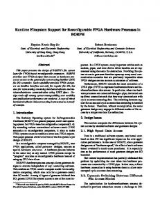
The current interconnection system bases on classical buses or on crossbar like circuit-switched ([13]) interconnection systems. But the advances in MPSoC design do not allow any longer for a ’one-entity’ communication system. Signal propagation delay and area considerations call for distributed packet-switched interconnection systems provided by NoCs. Consequently, we introduce a NoC into the MPSoC platform. The routers connected with the modules and each other establish the communication links between the modules (PEs, host processors, memories, peripherals,...) in the MPSoC. They receive flits (flow control digits) and forward them into the direction of the target module. A flit is a one-cycle packet consisting of a header containing the target module address and a payload containing the address within the module and data. There exist two kinds of flits: Best Effort (BE) and Guaranteed Traffic (GT) which form the different traffic types. BE flits will be forwarded in a router if the output of a router in destination direction is free. The destination direction is determined by the routing mechanism and bases on the target address in the flit header. Different routing algorithms are available (deterministic or adaptive) and can be used in a specific NoC realization. Round robin arbitration between all input ports is used in case two BE packets want to get access to the same output port in the same clock cycle. If a BE flit cannot be forwarded in a specific clock cycle it remains in a small FIFO which exists in every input port. GT on the other hand bases on the reservation of a virtual channel between two communicating modules. In the routers along the channel the corresponding input and output ports are reserved for GT flits of this channel. A GT reserved output port knows whether and from which input port the GT flit has to be forwarded. As soon as a GT flit arrives at that input port the output port forwards it. As an example look at Fig. 2 where a combined BE-GT router can be found. In this example the router has 4 ports (north, east, south and west). Every port is bidirectional consisting of an input and an output part and in every port there is the differentiation between BE and GT flits. This router is part of a reserved GT channel. The GT crosses the router from south to west and vice versa. Note, that a GT channel is always bidirectional in the sense of our NoC. In the west output port the GT reserve register is set
Input port
GT flit
III. N ETWORK - ON -C HIP A RCHITECTURE
North Header Bit: BE
provide enough free processing power before new tasks and applications can be started. The data transfer must neither be the bottleneck nor the indeterminable variable in the real-time considerations of the whole MPSoC but have to satisfy specific bandwidth and latency requirements. Thus, we enhance the interconnection system to packet-switched NoCs in order to provide the communication resources and the determinism and predictability for data transfers via Guaranteed Traffic channels. The CoreManager concept is extended by a methodology which allocates and frees the GT channels between the PEs and memories for real-time MPSoCs. This methodology is a channel allocation unit we call NoCManager which is described in section IV and V.
Input port Input port
South Fig. 2. Block diagram of an example combined BE-GT router with 4 bidirectional ports. As an example a GT channel between port west and south is established and the GT flits between both ports are directly forwarded. The FIFOs for BE traffic in the input ports are not shown because of clearness.
to SOUTH. Thus, as soon as a GT flit arrives at input port south it is forwarded directly to output port west and put out of the router. The BE routing is bypassed in that case and forwarding of BE flits in direction west from any other input port is stalled. Due to the fact that every router in the NoC works the same way, a GT route is constituted between two modules. As can be seen from Fig. 2 GT routing is done implicitly according to the reserved input-output pair (here the SOUTHWEST/WEST-SOUTH pair) and the GT reserve register. Therefore, the routing algorithms only apply to BE traffic. The target address in the flit header is not considered at GT flits. The GT reservation is done by the NoCManager which sets the GT reserve registers in the routers’ ports explicitly. A GT route is cleared via a GT tear down flit which is send along the route. This packet can be initiated by any of the two modules communicating via this GT route. Only one channel can be reserved at one port and across one link reducing router size and simplifying router complexity and global synchrony in case of different clock domains. Basically, GT flits are the same as BE flits except for 1 bit which identifies them as GT (and except for ignoring the target module address in the flit header). The determinism of GT is the only opposite between GT and BE traffic. Due to reservation a GT flit will always be forwarded as soon as it arrives at a router independent of possible congestions which only affect BE traffic. If at a port a channel is reserved but in a cycle no GT flit has arrived, the free port will be used for BE flits.
Global Memory I (SDRAM)
Router A
Task Queue
Core Manager
read XML C++ data base
Peripherals
NoC Manager Global Memory II (SDRAM)
XML description
Host Processor
Router D
Router B
Other units
genHDL
DSP/ASIP I
synthesizeable VerilogHDL model
DSP/ASIP II
genSim NoCManager + MPSoC top level module and router connection
C++/SystemC simulation model
DMA I DMA II Global Memory III (SDRAM)
Router C
template library
DSP/ASIP III DSP/ASIP IV
Fig. 4.
NoC and MPSoC top level generation flow.
MPSoC
Fig. 3. Block Diagram of the modified example MPSoC platform with NoC and NoCManager.
The topology of the NoC can be an arbitrary one. In the routers only the number of ports and the BE routing algorithm have to be adapted to the intended topology. But it has no effect on the GT routes and GT flit forwarding. The NoCManager can be used for any kind of topology as well - regular and irregular. One router per module results in high area overhead due to NoC. Therefore, for more specific MPSoCs where communication patterns between submodules can be appraised, it might be often useful to apply more specific NoCs. E.g. communication between control processor and slave PEs in our MPSoC platform will not be high because all data transfers to or from the PEs are done via DMA and they only communicate with the CoreManager. Additionally, some I/O systems like VGA or streaming interfaces to digitalanalog-converters do not need a high bandwidth link to host processor or slave PEs but high bandwidth access to global memories. In such cases it can be useful to delete a link reducing routers’ size or to attach several modules of less bandwidth to the same router. In Fig. 3 a possible example of a specific NoC topology suitable for our modified MPSoC platform can be found. Note, Fig. 3 does not imply that this is the best area-performance trade-off for our MPSoC platform. Moreover, a realistic NoC based implementation will have at least 8 or 16 DSP/ASIP elements instead of only 4. Figure 3 is just an example to illustrate the principle of our MPSoC platform realized with an irregular NoC topology. However, for the purpose of this paper we will restrict to mesh based NoC topology, where every submodule has a direct connection to exactly one router. They are often adopted in literature and research because of their very regular structure, simple routing mechanisms, easy adoption and the equality of all routers in the MPSoC. Mesh based NoCs also offer alternative links for a communication channel between two modules providing high combined bandwidth and reducing risk of congestion at bottlenecks. But, once more, neither the NoC design and generation flow nor the GT channel feature
and the NoCManager are restricted to this mesh topology. In order to test and realize different topologies, sizes and types of NoCs we use an automated generation flow for the interconnection in the MPSoC. The network is described in an XML format. Modules and routers in the MPSoC and links between them are defined in the XML file and read by a C++ framework. It can be defined arbitrarily which module or router is connected to which other module or router allowing any architecture or topology. The framework in turn generates the HDL description and a C++/SystemC simulation model of the MPSoC where routers and submodules are included as already existing entities. While the modules are provided by third parties or developed newly the routers are provided as templates in a library. Their data width, address width, FIFO size and some other factors can be parameterized resulting in highly automated design of MPSoC and reuse of available routing components. During the generation process they are included and instantiated as parameterized components in the MPSoC. The interconnection and MPSoC top level generation flow can be found in Fig. 4, too. IV. GT C HANNEL A LLOCATION VIA N O CM ANAGER The assignment of computation resources to an application and its tasks is done via the CoreManager explained in section II. But as communication becomes as important as computation, guarantees concerning bandwidth and latency and the assignment of Guaranteed Traffic channels to the communicating modules are necessary, too. The NoC which will be used for our MPSoC provides GT services. Finding the virtual GT channels between two modules and allocating them is the job of the NoCManager (NoCM). The NoCM has knowledge about all links in the MPSoC (and the according routers) and whether they are already allocated or not. As soon as a module needs a GT channel to another module it requests channel reservation at the NoCM. This, in turn, solves a shortest path problem in the graph formed by the NoC. Then, the resulting channel is allocated by informing the according routers reserving the ports and the module which requested the GT channel is informed about establishment of the channel. Especially for the MPSoC platform concept
described in section II the NoCM is a natural enhancement, Fig. 3 which can be included as the next step after task scheduling as part of the DMA transfers of program and data from global memory to the slave PEs. The CoreManager sends information about data transfers to the NoCM. The NoCM, in turn, reserves a channel and then instructs the DMA or the PEs itself to do data transfer via GT even without the necessity of a destination address in the header due to GT implicit routing. When the transfer is completed, DMA (or the slave PEs) free the GT channel via a tear down flit along the route. The NoCM is then informed by the routers along the GT route about teardown of the route and deallocation of the according ports. They are now available for other channels again. When the NoCM has found a free channel through the NoC, informing the routers and locking the appropriate ports can be done in two ways. Either the NoCM sends a lock packet along the route via source routing or the ports in the different routers are allocated via direct connections between NoCM and all routers. In the first case the NoC itself is used for route locking. No additional and special connections are necessary. But travel of lock packet through the NoC will take some time and delays the data transfer additionally. Next, before the lock packet can allocate the routers’ ports it has to get to the start point of the route what is an additional way to travel. Direct connections on the other hand can allocate the route in just one or two clock cycles speeding up channel allocation significantly. Due to the automatic generation of the NoC (the interconnection between routers and modules) and also the NoCM (as will be seen later) out of the XML description, addition of special connections between NoCM and routers is automated, too, and completely transparent for the MPSoC designers. We decided to use direct connections between channel allocator and routers which can be found in Fig. 3 as dotted lines because of the advantages in allocation delay and the possibility for automated inclusion. It is important to point out a virtual channel in the sense of this paper is a bidirectional connection. The requesting module must be able to send request packets for different addresses to the requested module e.g. in case of random read accesses with deterministic latency and the requested module must be able to answer with deterministic latency and bandwidth. We know about the problem of wasting bandwidth due to the probably not fully loaded virtual channel in both directions. Extensions to several virtual channels along the same link with the help of slot reservation tables like in [3] are imaginable as well. The NoCM would be able to handle this as will be described in more detail in the next section. V. A RCHITECTURE OF N O CM ANAGER From the last section we see the NoCM has to solve the shortest graph problem in a graph description of the MPSoC NoC in order to find a virtual channel (path) through the NoC. Solving graph problems in hardware is an area of research on its own and often hard to realize in acceptable time. However, the graph is known at design time due to the fix structure of the
NoC and therefore a hardware graph solution with acceptable area and time resources can be realized. First, the NoC must be mapped onto a graph representation consisting of nodes and edges. The modules and the routers are represented by nodes. Links are the edges between the nodes. If a (bidirectional) link exists between two routers, two modules or a router and a module, the corresponding nodes will be connected. In Fig. 5 mapping of an example NoC onto a graph representation can be found. The mapping process results in a graph where all edges are bidirectional and have the same weight allowing to disregard it. The weight indicates how many cycles a flit needs for one hop from one router entrance to the entrance of the next router or module. So far, we assume the clock cycles a flit needs for such a hop to be the same for all hops in the NoC. For hardware realization of the graph representation we base on the work of Huelsbergen et al. in [14] and [15]. Nodes are represented by simple, unconnected, horizontal and vertical wires. If an edge between two nodes exists, the horizontal node-wires will be connected with the vertical node-wires via AND-OR-gates. The transformation of the NoC graph representation to the hardware realization as HArdware Graph ARray (HAGAR) or graph matrix can be found in Fig. 5. For example let us consider node (0). It has connections to nodes (1), (2) and (3). The horizontal wire for node (0) has AND-ORconnections to the vertical wires of nodes (1), (2) and (3) in the HAGAR realizing the unidirectional edges from node (0) to nodes (1), (2) and (3). The horizontal wires of nodes (1), (2) and (3) have AND-OR-connections to the vertical wire of node (0) realizing the edges from nodes (1), (2) and (3) to node (0). These 2-fold connections result in a hardware representation of the bidirectional edges (links). Unidirectional edges (links in the NoC) would be possible either but are not useful in the sense of our virtual channel allocation. If we want to know whether a node can be reached from another node, the starting node will set a logic value of ’1’ on the according horizontal wire. This logic value spreads across the wire to the AND-OR-gates and activates the reachable nodes (vertical wires). These reached nodes are set to logic ’1’ on the horizontal wires and, in turn, activate the next nodes on the vertical wires via the connected AND-OR-gates and so on until the last reachable node. As an example, let us consider the way from module (3) to module (5). First, we activate the initial node (3) in the HAGAR by setting a logic ’1’ on the horizontal wire of node (3). For the moment, let us assume the AND-OR-gates were simple OR-gates. In that case, the logic ’1’ on the wire of node (3) will spread across the ORgates along the vertical node (0) wire. That means node (0) is activated and detected. Now node (0) is activated on the horizontal wire via a logic ’1’ (additionally to node (3)). This ’1’ spreads across the OR-gates on the vertical wires of node (1), (2) and (3). Next, the horizontal wires of nodes (1) and (2) are activated additionally via logic ’1’ (node (3) is already activated because it was the initial node and node (0) stays active from the previous step). The activation of node (1) on horizontal wire leads to activation of node (0), (2) and (4) on
NoC
Graph Representation
router (0)
router (1)
module (3)
module (4)
3
2
5
Hardware Graph Array (HAGAR) Detection of Activated Column (Node)
Node (0)
Node (1)
Node (2)
AND -OR
Node (0)
AND -OR
Node (2)
Node (3)
AND -OR AND -OR
AND -OR
Node (1)
Activate Initial Node
4
0
router (2) module (5)
1
Node (4)
clock
Node (5)
AND -OR AND -OR
AND -OR
AND -OR
AND -OR
Node (3)
AND -OR
Node (4)
AND -OR
Node (5)
OR &
0
AND 0
=
0
ANDOR
Q
C
Q
R A B
Edge active FlipFlop
Activate/Deactivate Edge Clock Asynchonous Reset
Fig. 5. Transformation of an example NoC topology (upper left side) to its graph representation (upper right side) and then to the hardware realization as graph matrix (HAGAR) (in the middle). On the lower side the detailed circuit of the AND-OR-gate used in the graph matrix is illustrated including the edge activation Flip-Flop.
the vertical wires. The activation of node (2) on horizontal wire leads to activation of node (0), (1) and (5) on the vertical wires. Now we have arrived at node (5) and the algorithm stops. But up to now we do not have the route from module (3) to module (5). We only solved a reachability problem and know, that module (5) can be reached from module (3). If we want to go one step further and find the shortest path in the NoC we have to consider the weight of the edges and the sum of weights along the route, too. While the simple reachability problem can be solved without clocking, for shortest path solution we need a clock. Look again at Fig. 5. In the first cycle we activate the starting node, the module
where the virtual channel shall start. Via the AND-OR-gates (they can still be seen as simple OR-gates) all nodes reachable in one hop are activated and detected on the vertical wires. In opposite to solution of reachability problem, for shortest path the reached nodes have to remember the node which activated them for the first time. In the next cycle all nodes which were activated on the vertical wires are set to logic ’1’ on their horizontal wires. They activate other nodes on the vertical wires again. This goes on until the intended end node is reached. In our example from above, in the first clock cycle node (0) remembers that it was activated by node (3). In the second clock cycle node (1) and (2) remember that they were activated by node (0). In the third clock cycle node (5) remembers that it was activated by node (2) and node (4) remembers that it was activated by node (1). The intended end node (5) was reached and the algorithm is stopped. (No new horizontal wires will be activated.) It can happen that a node is activated by more than one node in the same cycle or it is driven high again although it already has been activated. In such cases the node only remembers one and the first of the predecessor nodes. From the example it can be seen that in step 3 the horizontal wires of nodes (1) and (2) are activated in the same clock cycle in parallel. This is the general behavior of the NoCM. All nodes which were reached in a cycle are activated in the next cycle parallelizing search of a route in different directions. If two or more search directions arrive at a node in the same cycle only one of the possible predecessors is chosen. All arriving routes at this node have the same length. So, it is not of importance which one is chosen. If a search direction arrives at a node which is already activated (logic ’1’) only the predecessor which activated the node first will be stored. The search direction which arrives later at this node dies out. If in a cycle no new nodes (vertical wires) are activated without having reached the intended end node the end node will not be reachable. In the NoC this means, there is currently no free path for a GT channel between the two modules which want to communicate via GT. In such a case finding a GT channel can be retried later or a fail message can be send to the GT channel requester. As soon as the end node is reached the path is backtracked. Starting from the end node backtracking bases on the stored predecessor nodes. In our example, node (5) is the end node and has node (2) stored as predecessor node. In the next cycle, the predecessor of node (2) (node (0)) is extracted and in the last cycle the predecessor of node (0) is found as node (3) which is also the starting node. Backtracking comes to an end and has found the path of the GT channel from module (3) to module (5) and vice versa. During backtracking in every cycle a new router along the route is extracted and this router is informed immediately about the GT channel crossing it. Path backtracking and channel allocation are parallelized by that. The router receives two IDs of its neighbor routers along the GT route. The router associates the router IDs received from the NoCM with the two corresponding ports and sets the GT reserve register in
Direct connection to/from routers
NoC connection
GT request queue
Edge Activation Path search failed
Path Search/ Graph Matrix
Reserve links and ports in routers
wait GT request queue
Links and ports in routers deallocated: activate edges
NoC interface
Deactivation
the output ports appropriately. (Compare also to Fig. 2 where the corresponding ports are south and west.) Up to now the AND-OR-gates could be seen as simple ORgates. But the edges (links) which are found at backtracking have to be deactivated in the graph matrix. Otherwise a link could be used for another GT channel although it is already in use and we do not allow more than one GT route crossing a link. Deactivation of the edges is done in the AND-ORgates. A 1-bit flipflop per edge is used for activation or deactivation of this edge. The activation bit is AND-gated with the horizontal wire of a node, Fig. 5. Thus, if an edge is deactivated the logic ’1’ on the horizontal wires will not cross the AND-OR-gates and the existing but already allocated link is not detected at next path search. This ensures already allocated links not to be allocated again. When a GT virtual channel is teared-down by an unlock packet send along the channel route, the ports and links of the corresponding routers are freed. The router sends this information to the NoCM which reactivates the edges in the graph matrix by setting the 1-bit activation flipflop to logic ’1’. Now the AND-OR-gate can be crossed again, the link will be detected and used. In every cycle one hop of the channel path through the NoC is found. Thus, signal propagation through graph matrix from the starting node to the end node will take as many clock cycles as the shortest path has hops. Path backtracking takes as many cycles, too, because in every clock cycle one predecessor node is extracted in order to achieve high clock frequencies. The hardware solution of the shortest graph problem consisting of path search/graph matrix, path backtracking and edge activation is the heart of the NoCManager. A queue for the incoming GT channel requests and a submodule for informing the modules in the MPSoC about reservation of the GT route complete the NoCM as can be seen in Fig. 6. Because of the NoCM’s global knowledge about the NoC graph and the current allocation of links it can find free GT routes where simple distributed principles like in [7] will fail. It also has knowledge about the length of the routes by a simple counter. This knowledge can be send to the GT requester providing an explicit number of hops between the communicating modules and allowing for exact computation of communication latency which could be taken into account by the modules. It is important to point out the NoCM is not limited to meshbased NoCs. The connections between modules and routers can be arbitrary allowing for adaption to other topologies or completely individual and irregular NoCs. The simple mapping from NoCs to graph hardware realization allows for efficient automated generation even in the case of completely irregular NoC topologies. The XML-file used for NoC description in our MPSoC platform is very suitable for this. Modules and routers are the nodes and realized as the column detect register and according wires in hardware (look at Fig. 5), the links between modules and routers are the edges and realized as AND-OR-gates with an activation-flipflop. So, the NoCM is simply generated along with the top level interconnection
Port@Router reservation
Path Backtracking Graph Problem
Fig. 6.
Inform GT requester
NoCManager
Block diagram of the NoCManager.
of the MPSoC within seconds (Fig. 4). Though it is not necessary up to now, the NoCM could support slot table based GT channels as well allowing more than only one GT channel at a link. Simply the connection between horizontal and vertical wires in Fig. 5 have to be enhanced via more than just one AND-OR-gate. If someone wants to allow 4 GT channels on a link, 4 AND-OR-gates will be used in parallel and combined via an additional OR gate. So, the 4 GT channels on one link can be a allocated and deallocated via the activation-flipflop. Only if all 4 flip-flops are deactivated the link will not be used for new GT channel allocation. VI. N O CM ANAGER R ESULTS Basically, in this paper we want to present the concept of an MPSoC platform where computation but especially communication resources can be managed efficiently. In depth results of the concept shall not be provided here. Especially, simulations of the complete MPSoC platform and applications mapped to it are not available up to now. But there exist results about the NoCManager concerning area consumption and computation latency. The NoCM was developed in VerilogHDL and generated out of the XML description for 5x5, 8x8 and 10x10 mesh NoCs. It was synthesized with Synopsys Design Compiler, 130 nm UMC library. The resulting area consumption can be found in Table I where the FIFOs of the GT request queues are not included. The area consumption scales approximately linearly with the number of links and modules or routers in a mesh NoC and is quite acceptable even at a 10x10 mesh with 200 nodes (100 modules + 100 routers) consuming 59 kN AN Ds. Timing analysis after synthesis proved, the graph solution part as the dominating part of the NoCM can run easily at 1 GHz even in 130 nm UMC technology. The shortest virtual
TABLE I A REA SUMMARY OF THE N O CM ANAGER . NoC Type
5x5
8x8
10x10
No. Modules,No. Routers
25
64
100
No. Links
130
352
560
Area graph matrix (kNAND)
4.4
12.9
20.1
Area edge activation (kNAND)
1.2
3.2
5.0
Area path backtracking (kNAND)
5.2
16.0
24.3
Area NoCManager (kNAND)
18.1
39.2
58.9
Area graph matrix (µm2 )
22, 801
66, 962
109, 025
Area edge activation (µm2 )
6, 065
16, 422
26, 127
Area path backtracking (µm2 )
27, 044
82, 981
126, 425
Area NoCManager (µm2 )
93, 670
203, 458
306, 823
channel from the upper left to the lower right corner in a 5x5 mesh is 10 hops and in a 10x10 mesh it is 20 hops. At 1 GHz this leads to only 2·10·1 ns = 20 ns and 2·20·1 ns = 40 ns, respectively, for finding a path in the graph matrix and path backtracking. Additionally, there are 3 clock cycles for getting the GT request from the queue and sending the allocation information to the GT requester. A signal processing MPSoC in 130 nm technology typically runs at 200 M Hz or at most 500 M Hz. In order to make use of the possible high clock frequency of the graph solution part, the heart of the NoCM can run at higher frequency than the remaining MPSoC. Then, the NoCM of an MPSoC containing 25 modules (what is realistic at 130 nm technology) and equipped with a 5x5 mesh NoC would need typically 10 to 15 500 M Hz clock cycles in order to find and allocate a GT channel (20 ns are 10 cycles at 500 M Hz). The prize for GT channel allocation is therefore very acceptable in terms of clock cycle delay and area consumption. Thus, the NoCM can manage communication resources at task-level and at run-time. VII. C ONCLUSION In this paper we described the concept of a run-time NoCManager allocating virtual GT channels on task-level for NoC based MPSoCs. The NoCM is able to set up virtual channels in NoCs in few cycles providing guaranteed traffic with acceptable area consumption and independent of the underlying network architecture. The global knowledge about the virtual channel utilization in the NoC allows for successful search and allocation of channels although the NoC is highly loaded offering much higher utilization than in simple distributed systems. A software solution of the NoCManager might be possible as well. Solving the shortest path problem on a microcontroller can be realized. But analysis of a graph containing 200 nodes and 560 edges (like at a 10x10 mesh) is not easy to realize in software even though all edges have the same weight. It will consume long computation time and require additional memory for storage of the NoC graph representation and program code. It will not be possible to find and allocate the GT channels at run-time within few dozen
clock cycles. Only the speed-up due to hardware realization and the parallelization of the route search because of activating different nodes in parallel in the same cycle allows for efficient channel allocation on task level. The NoCManager along with the CoreManager form the base of a run-time and real-time capable MPSoC platform with dynamic assignment of tasks to processing elements transparent for the user. Next, applications have to be mapped onto the MPSoC platform and simulations will be done giving information about the efficiency of the combined task scheduling and allocation of communication resources. R EFERENCES [1] D. Bertozzi et al. NoC synthesis flow for customized domain specific multiprocessor systems-on-chip, Trans. on Parallel and Distr. Syst., 16(2), 2005 [2] K. Goossens, J. Dielissen, O.P. Gangwal, S.G. Pestana, A. Radulescu, E. Rijpkema. A Design Flow for Application-Specific Networks on Chip with Guaranteed Performance to Accelerate SoC Design and Verification, In Proc. of the Design, Automation and Test in Europe Conference and Exhibition (DATE), March 7 - 11 2005, pp. 1182-1187 [3] K. Goossens, J. Dielissen, A. Radulescu. AEthereal Network on Chip: Concepts, Architectures and Implementations, In IEEE Design and Test of Computers, Vol 22(5):21-31, Sept-Oct 2005 [4] M. Millberg, E. Nilsson, R. Thid, A. Jantsch. Guaranteed Bandwidth using Looped Containers in Temporally Disjoint Networks within the Nostrum Network on Chip, In Proc. of the Design, Automation and Test in Europe Conference (DATE), Feb. 16 - 20 2004, pp. 890-895 [5] A. Hansson, K. Goossens, A. Radulescu. A Unified Approach to Constrained Mapping and Routing o Network-on-Chip Architectures, In Proc. of the 3rd International Conference on Hardware/Software Codesign and System Synthesis 2005, Jersey City, NJ, USA, pp. 75-80 [6] J. Hu, R. Marculescu. Energy-Aware Communication and Task Scheduling for Network-on-Chip Architectures under Real-Time Constraints, In Proc. of the Design, Automation and Test in Europe Conference (DATE), Feb. 16 - 20 2004, pp. 234-239 [7] D. Wiklund, D. Liu. SoCBUS: Switched Network on Chip for Hard Real Time Embedded Systems, In Proc. of International Parallel and Distributed Processing Symposium (IPDPS), April 22-26, 2003, pp. 8-15 [8] O. Moreira, J. J.-D. Mol, M. Bekooij. Online Resource Management in a Multiprocessor with a Network-on-Chip, In Proc. of the ACM Symposium on Applied Computing, 2007, Seoul, Korea, pp. 1557-1564 [9] N. Kavaldijev, G.J.M. Smit, P.T. Wolkotte, P.G. Jansen. Providing QoS Guarantees in a NoC by Virtual Channel Reservation, In Proc. of the International Workshop on Applied and Reconfigurable Computing (ARC), Delft, The Netherlands, March 2006 [10] J.P. Robelly, H. Seidel, K.C. Chen, G. Fettweis. Energy Efficiency vs. Programmability Trade-Off: Architectures and Design Principles, In Proc. of Design, Automation and Test in Europe Conference (DATE) 2006, pp. 587-592 [11] H. Seidel, G. Fettweis. A Task-Based MPSoC Programming Model, International System on Chip (SoC) Design Conference (ISOCC), Seoul, Korea, 26th/27th October 2006. [12] T. Limberg, B. Ristau, G. Fettweis. A Real-Time Programming Model for Heterogeneous MPSoCs., In Proc. of the International Workshop on Systems, Architectures, MOdeling and Simulation (SAMOS’08), Samos, Greece, July 21 - 24 2008, pp. 75, 2008. Springer-Verlag Berlin Heidelberg 2008 [13] M. Winter, G. Fettweis. Interconnection Generation For System-on-Chip Design, In Proc. of International Symposium on System-on-Chip 2006, Tampere, Finland, Nov. 13-16, 2006, pp. 91-94. [14] L. Huelsbergen. A Representation for Dynamic Graphs in Reconfigurable Hardware and its Application to Fundamental Graph Algorithms, In Proc. of ACM/SIGDA 8th International Symposium on Field Programmable Gate Arrays 2000, Monterey, California, USA, pp. 105 - 115 [15] O. Mencer, Z. Huang, L. Huelsbergen. HAGAR: Efficient Multi-Context Graph Processors, In Proc. of the Reconfigurable Computing Is Going Mainstream, 12th International Conference on Field-Programmable Logic and Applications, 2002, pp. 915 - 924