I. INTRODUCTION. Estimation of relative 3D camera position and orientation. (pose) is one of the most ... EKF was used for the first time to compute the 3D ...
(IJACSA) International Journal of Advanced Computer Science and Applications, Vol. 3, No.4, 2012
A New 3D Model-Based Tracking Technique for Robust Camera Pose Estimation Fakhreddine Ababsa University of Evry, 40 Rue du Pelvoux, 91020 Evry, France
Abstract—In this paper we present a new robust camera pose estimation approach based on 3D lines features. The proposed method is well adapted for mobile augmented reality applications We used an Extended Kalman Filter (EKF) to incrementally update the camera pose in real-time. The principal contributions of our method include first, the expansion of the RANSAC scheme in order to achieve a robust matching algorithm that associates 2D edges from the image with the 3D line segments from the input model. And second, a new powerful framework for camera pose estimation using only 2D-3D straight-lines within an EKF. Experimental results on real image sequences are presented to evaluate the performances and the feasibility of the proposed approach in indoor and outdoor environments. Keywords-Pose estimation; Line tracking; Kalman filtering; Augmented Reality.
I.
INTRODUCTION
Estimation of relative 3D camera position and orientation (pose) is one of the most challenging problems in computer vision. Indeed, the knowledge of the camera pose is useful for numerous applications, including motion analysis, robotic control tasks, and Augmented Reality (AR) [1][2]. For example, Dasgupta and Banerjee [3] developed an AR system for autonomous navigation which uses a panoramic vision. Their system allows augmenting, via a laptop, the real video by simultaneously viewing an artificial 3D view of the scene. During the last years, several approaches based on natural features (points, planes, edges, etc.) extracted from the image scene have been developed. The mean idea of these techniques is to locate the camera in three dimensions given a sequence of 2D intensity images of the scene containing the 3D features whose positions and orientations are known relative to a reference frame. When the correspondences between 2D features extracted from the image and 3D features defined in the world frame are established, the problem is then solved using 2D-3D registration techniques. Numerical nonlinear optimization methods like the Newton-Raphson or LevenbergMarquardt algorithm are generally used for the minimization [4][5][6]. Thus, Wang et al. [7] propose a 3D localization approach using Harris-Laplace interest points as natural landmarks. Their localization system is composed of two stages: coarse localization from a location vector space model (LVSM) and affine localization from the location database using a voting algorithm. The pose recovery of the camera is obtained from essential matrix decomposition. Line-based methods are more robust and more efficient than point-based techniques. Indeed, line features are present in many scenes and
are more visible than points under a wider range of lighting and environmental conditions. Wuest et al. [8] present a modelbased line tracking approach that can handle partial occlusion and illumination changes. The camera pose is computed by minimizing the distances between the projection of the model lines and the most likely matches found in the image. Drummond and Cipolla [9] propose a novel framework for 3D model-based tracking. Objects are tracked by comparing projected model edges to edges detected in the current image. Their tracking system predicts the edge locations in order to rapidly perform the edge search. They have used a Lie group formalism in order to transform the motion problem into simple geometrics terms. Thus, tracking becomes a simple optimization problem solved by means of iterative reweighed least squares. Recently, Comport et al. [10] propose a real-time 3D model-based tracking algorithm. They have used a visual servoing approach to formulate the pose estimation problem. A local moving edges tracker based on tracking of points normal to the object contours is implemented. In order to make their algorithm robust, they have integrated a M-estimator into the visual control law. Other approaches have also been applied where different features have been combined to compute the camera pose. Ababsa and Mallem [11] propose to combine point and line features in order to handle partial occlusion. They integrated a M-estimator into the optimization process to increase the robustness against outliers. Koch and Teller [12] describe an egomotion estimation algorithm that takes as input a coarse 3D model of an environment. Their system uses a prior visibility analysis to speed initialization and accelerate image/model matching. For real-time applications, extended Kalman filtering (EKF) is the most widely used method for recursive estimation. EKF allows also to achieve noise and disturbance rejection and to enhance estimation accuracy. EKF was used for the first time to compute the 3D location by Wilson et al. [13]. Yu et al. [14] propose an EKF based method to recover structure and motion from image sequences. The EKF is used to estimate the object’s pose and to refine the positions of the model points in the 3D space. More recently the same authors propose an EKF algorithm for pose tracking using the trifocal tensor [15]. Their approach is also based on natural points and incorporates the tri-focal constraint into the measurements model. Yoon et al. [16] present a model-based object tracking to compute the 3D camera pose. Their algorithm uses an EKF to provide an incremental pose-update scheme in a prediction-verification framework. In order to enhance the accuracy and the robustness of the tracking against occlusion, they take into account the
31 | P a g e www.ijacsa.thesai.org
(IJACSA) International Journal of Advanced Computer Science and Applications, Vol. 3, No.4, 2012
measurement uncertainties associated with the location of the extracted image straight-lines. Lippiello et al. [17] developed an algorithm for pose estimation of a moving object. In order to enhance the robustness with respect to measurement noise and modeling error, they proposed an adaptive version of the EKF customized for visual applications. Jiang and Neumann [18] propose an EKF-based extendible tracking method that can extend tracking from prepared to unprepared regions of the environment by auto-calibrating a 3D structure of a priori unknown 3D lines. Other approaches use Simultaneous Localization And Mapping (SLAM) to track the camera pose while building a 3D map of the unknown scene. William et al. [19] proposed a recovery module that finds the pose of a camera using a map point features created by a single-camera SLAM system. They used an efficient version of RANSAC to achieve pose hypotheses verification and to reject outliers. Davison et al. [20] used the EKF to estimate the 3D trajectory of a monocular camera moving through an unknown scene. The core of their system, named MonoSLAM, is the online creation of a sparse map of natural landmarks within a probabilistic framework. However, the main problem with most existing monocular SLAM techniques is a lack of robustness when rapid camera motions, occlusion and motion blur occur. In this paper we present an original robust camera pose tracking using only straight lines and which differs from existing works. We propose to combine an EKF with a RANSAC scheme in order to achieve a robust 2D-3D lines matching. This gives an efficient solution for outlier’s rejection. To our knowledge such solution has not been explored before. Furthermore, we have combined the 2D-3D lines correspondence constraints for object pose estimation, developed by Phong et al. [21], with an EKF in order to update recursively the camera pose. We have compared our results with classical approaches where pose estimation is solved using least square approaches [22][23][24]. Our method requires no training phase, no artificial landmarks, and uses only one camera. The rest of the paper is structured as fellows: In section II, we describe the camera pose estimation problem formulation when using straight lines, and we also give a complete implementation of the Extended Kalman Filter to update the camera pose recursively over the time using 2D and 3D lines features. In section III, we explain how we have expended the RANSAC scheme [25] in order to achieve robust 2D-3D lines matching. In section IV, we show experimental results and evaluations; we discuss also the merits and the limitations of the proposed approach. Conclusion and future work are presented in section V. II.
CAMERA POSE ESTIMATION ALGORITHM
In any Kalman Filter implementation, the system state is stored as a vector. In our algorithm the state is represented by the position and the orientation of the camera with respect to the world coordinate system. For computational we use a unit quaternion to represent the rotation [26]. Thus, the state vector is given by:
X q0
qx
qy
qz
tx
ty
tz
(1)
We denote the camera state at time t by the vector X t . The EKF is used to maintain an estimate of the camera state X in the form of a probability distribution P X t X t 1 , Z t , where Zt is the measurement vector at time t. The Kalman filter models the probability distribution as Gaussian, allowing it to be represented by a covariance matrix . In an extended Kalman filter, the nonlinear measurements and motion models are linearised about the current state estimate as Jacobian matrices [27][28]. Our algorithm follows the usual predict-refine cycle, whereby the state X is predicted at timestep t, and measurements are used to refine the prediction.
A. Time update The time update model is employed in order to predict the camera pose at the following time step. In our case, the time update is simple because of the fact that we estimate the camera pose at each frame of the images sequence. Therefore the 3D cameras pose between two successive frames changes very little. The time update equation is then given by :
X t A X t 1
(2)
Where A is 77 identity matrix. The time update step also produces estimates of the error covariance matrix from the previous time step to the current time step t. To perform this prediction we use the general update equation of the Kalman filter:
t A t A Qt 1
(3)
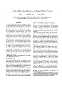
Where Qt represents the covariance matrix of the process noise. reflects the variance of the state distribution. B. Measurement model and estimate update The measurement update model relates the state vector to the measurement vector. Since our goal is to estimate the camera pose using only straight lines, we will first describe the constraint equation which relates the state vector to the 3D model lines and their corresponding 2D image edges. We choose to base our technique on line features, rather than points, because this approach is relatively unexplored in the vision literature. We consider a pin-hole camera model and we assume that the intrinsic camera parameters are known. The world coordinate frame is a reference frame. All the 3D model lines are defined with respect to it. Let Li be a 3D line. Li is represented with the Cartesian coordinates of its two end-points P1i and P2i (see figure 1). The points P1i and P2i in world coordinates can be expressed in the camera frame as well :
Pi R Pi T 1/ C 1/W i i P2 / C R P2 / W T
(4)
32 | P a g e www.ijacsa.thesai.org
(IJACSA) International Journal of Advanced Computer Science and Applications, Vol. 3, No.4, 2012
Where the 33 rotation matrix R and the translation vector T describe the rigid body transformation from the world coordinate system to the camera coordinate system and are precisely the components of the camera state vector. P1
ni
Yw
Ow
Li
Xw
Where
Zw
P2
li
mi2 ni1
Camera frame
Image plane
ni2 Xc
Oc
Figure 1. Projection plane. The model line, its projection onto the image and the center of projection OC are coplanar.
We can see that the points P1i/ C , P2i / C and the center of projection OC are coplanar. N i is the unit vector normal to this plane. N i can be expressed in the camera coordinates frame as follows :
O P i OC P1i/ C N i C 1/ C OC P1i/ C OC P1i/ C
T
T
i i i u2 v2 and m2 defined in the
2D image coordinates frame. The points m1i and m 2i can be expressed in the camera coordinate frame as follows:
m1i / C K 1 u1i i 1 i m 2 / C K u 2
1
v1i 1
T
v 2i
T
(6)
Where the matrix K contains camera calibration parameters, such as focal length, aspect ratio and principal point coordinates. A measurement ni of the unit vector N i normal to the projection plane is thus given by (see figure 1): ni n1i n 2i (7)
n zi
T
N iy
(9)
T N zi
vt represent the noise term in the measurement input with covariance Rt. The noise is due to the uncertainty in the measured image position of the end points of the extracted 2D lines. The nonlinear function h(X) in measurement equation (8) relates the state to the measurement input. Three 2D-3D line correspondences are sufficient in theory to recover 6-DOF camera pose [29] through in practice mores line may be required to increase accuracy. The state estimate and covariance are refined after each feature measurement zt using the standard equation of the EKF as follows:
K t t H tT H t t H tT Rt
1
X t X t K t z t h X t
(5)
Furthermore, a measurement input of the normal vector N i can be obtained from the image data. Indeed, image line matched with model line belongs also to the projection plane defined above. Let li be a 2D image line corresponding to the 3D line Li. In similar manner li is represented by its two i extremities m1i u1i v2
z n n i n i i x y t i h X t N i N x
i
m1i
Zc
z t h X t vt (8)
World frame
i
Yc
Combining equations (5) and (7), a measurement equation can be written, for each matching event Li li :
i
Ni
t
t
(10)
K t H t t
Where Ht is the Jacobian matrix defined by:
Ht
h X X
(11)
X X t
The measurement update model is executed once a set of 2D-3D matched lines become available. C. Iterated EKF The standard EKF method does not consider errors due to the linearization of the nonlinear function h(X) in the vicinity of X t . However, these errors can lead to wrong estimates and/or divergence of the camera pose. Since the nonlinearity is only in measurement equation, the Iterated Extended Kalman Filter (IEKF) is the best technique to deal with it [30][31]. The IEKF uses the same prediction equation as EKF, namely (2) and (3). The measurement update relations are replaced setting X t0 X t and doing iteration on :
Where
H tk
h( X ) X
X X tk
T T K tk t H tk H tk t H tk Rt
1
(12)
X tk 1 X tk K tk z t h X tk
33 | P a g e www.ijacsa.thesai.org
(IJACSA) International Journal of Advanced Computer Science and Applications, Vol. 3, No.4, 2012
For iteration number k 0,1, , N 1 . At the end of all iterations, X t X tN . The covariance matrix is then updated N based on X t according to :
t t K tN H tN t
(13)
The iteration could be stopped when consecutive values k 1 and X t differ by less than a defined threshold.
X tk
III.
ROBUST 2D-3D LINES MATCHING ALGORITHM
(a) (b) Figure. 2. Two frames from the recorded images sequence. (a) indoor scene. (b) outdoor scene.
In this section we explain the expansion of the RANSAC scheme that we have developed in order to achieve a robust matching algorithm that associates 2D edges from the image with the 3D line segments from the input model, and without using any verification algorithm. Let l i , i 1,...,N be a set of 2D edges extracted from the image and L j , j 1,...,M a set of 3D model lines. Our robust
3. Each candidate is tested against all the correspondences l i L j by computing, in the camera frame, the angle between the normal vector ni (see figure 1) associated with the image line l i and the transformed line R L j . If this
S15 S17
S16
S18
S19
6
S6 S3 S9
4
Y
S11
S7
S12
1
S8
2
0.5
S1
Z S4
lines matching algorithm is summarized as follows:
2. For each sample, compute the camera pose (R,T) using the IEKF algorithm described in section II.
S10 S13
1. Randomly sample subsets of four {li Lj} pairs of 2D and 3D lines. In theory a minimum three pairs are of lines are sufficient to compute an accurate rigid transformation.
S2
S14
S5
X
0 0
0 5
-0.5 10
15
20
25
-1
(a) (b) Figure. 3. 3D models of indoor and outdoor scenes used for experiments. (a) the office room model. (b) The frontage building model.
In order to estimate the camera pose accuracy we defined, in the camera space, the registration error . Given a set of correspondences between image edges and model segments the error corresponds to the normalized square sum of the sinus of the angular disparities i for each correspondence between image edge and the re projected model segments (Figure 1):
match is wrong with respect the pose , then the co sinus of the angle should be significantly larger than zero. 4. We choose the pose which has the highest number of inliers, i.e the for which all the pairs are within a fixed angle threshold. Hence, the obtained camera pose for the current image is robustly updated using only inliers of correspondences. IV.
EXPERIMENTAL RESULTS
The proposed camera pose estimation algorithm has been tested in real scenes and the registration accuracy was analyzed. The results are presented for both indoor and outdoor images (Figure 2). The indoor scene consists of a camera moving in an office room whereas the outdoor one corresponds to a moving camera pointing towards one frontage of a building. The frame rate of the recorded image sequences is about 25 frames/s and the resolution of the video images is 320240 pixels. The 3D models of the office room and the building frontage are known, they are composed, respectively, of 19 lines and 120 line defined by the 3D coordinates of their end points within the world coordinates frame (Figure 3).
Where M is the number of correspondences and i the angle between the two planes spanned by the camera center, the observed image edge li and the model segment Li (see figure 1). In our experiment we took M=10 correspondences. We have first considered that the data set has no outliers (100 % inliers or good matching) and we computed the registration error for several frames of the image sequence. Our algorithm was run on both the indoor and outdoor scenes. Similar results were obtained in both situations. Thus, for the indoor scenario, the mean error is about 5 m4.01 10 which corresponds to the mean angular
disparities m 0.28 . For the outdoor scene, we obtained 5 m3.43 10 and m 0.28 . Figure (4) shows the projection of the office model using the camera pose estimated by our algorithm, and as can see it is quite skewed. All the lines are fairly well aligned.
34 | P a g e www.ijacsa.thesai.org
(IJACSA) International Journal of Advanced Computer Science and Applications, Vol. 3, No.4, 2012
(a) (b) Figure 4.. Projection of the 3D models using the final camera pose estimate when the input data has no outliers. (a) indoor scene (b) outdoor scene
(a) Outliers = 30%
(b) Outliers = 50%
In the second experiment, we have evaluated the capacity of our robust algorithm to reject outliers in observed data. In our case, an outlier corresponds to a wrong feature matching between 2D and 3D line. For that, we have contaminated the input data set with different percentage of outliers, for both indoor and outdoor scenes, and have computed the corresponding registration error. The obtained results are summarized in table 1. TABLE I : EXPERIMENTAL RESULTS OF THE ROBUST ALGORITHM Outliers (%) 30% 40% 50% 60% Outliers (%) 25 % 37 % 50 %
Indoor scene m m(°) 0.37 4.9310-5 0.39 6.9510-5 0.42 7.8410-5 0.44 8.1810-5 Outdoor scene m m(°) 0.34 3.8110-5 0.37 5.5710-5 0.44 8.6410-5
Number of trials 4 12 50 240 Number of trials 4 6 56
As can be seen, our robust algorithm succeeded in all the cases to detect and delete the outliers. The camera pose is then estimated using the final data consensus which contains only the good 2D-3D lines correspondences. For example, in the worst case when 60% of the input data for the indoor scene (i.e. 6 lines correspondences among 10) are labeled as outliers, our algorithm was been able to identify the four inliers in the data. The camera pose returned using this inliers gives a registration error about 8.1810-5. This result demonstrates the robustness and the accuracy of the proposed approach. Furthermore, we note that the number of trials needed to get the best solution increase with number of outliers (for example 240 trials for 60% of outliers for the indoor scenario and 56 trails for 50% of outliers for the outdoor scene). This means more processing time and will decrease the real time performance of the algorithm. 40% of outliers (15 trials on average) represents a good compromise. Figure 5 shows the projection of the models using the pose estimated by our algorithm for different frames of the indoor and outdoor images sequence and when run with different percentage of outliers. We can see that all lines are well aligned, and in this cases, the outliers have not affected the registration performance of our robust algorithm.
(c) Outliers = 37% (d) outliers = 50% Figure. 5. Camera pose estimation results
Another advantage of our approach is its robustness to severe lines occlusion. Indeed, as the line constraint equation (see section II-B) for the cameras pose parameters was developed in the case of “infinite image line”. Any image points on the 2D line can be used to construct the corresponding projection plane. So, when partial occlusion occurs, it is enough to detect only small parts of the image edges to estimate the camera pose. In figure 6 we can see that several image edges are partially occluded (table and door for the indoor scene and because of the trees and the cars for the outdoor scene), in spite of that, the camera pose was successfully estimated. We analyzed the processing time needed for camera pose estimation on a Pentium IV with 3GHz. All computations were performed in Matlab. The pose estimation process using IEKF does not take much time. Indeed, we have tuned the parameters of the IEKF in such manner so that it converges in a few iterations (20 at the maximum). The processing time strongly depends only on the number of outliers in the current field of view. For example, the average time is about 28 millisecond per frame when having 40% of outliers in 10 input data for indoor scene. 3 milliseconds are used to estimate the camera pose with the IEKF and 25 milliseconds are measured for the time needed to reject outliers. We have also evaluated the 3D camera localization accuracy. For that, we considered the outdoor scene, and we compared the computed camera trajectory obtained with our algorithm with the ground truth data. The ground truth for position is provided by a Trimble Pathfinder ProXT GPS receiver giving a submeter accuracy, The covered distance is about 30 meters. The ground truth for rotation was obtained using an Xsens MTx gyro mounted rigidly with the camera [32].
35 | P a g e www.ijacsa.thesai.org
(IJACSA) International Journal of Advanced Computer Science and Applications, Vol. 3, No.4, 2012
The results of the experiments are given in figure 6 which shows the error between the ground truth data and the recovered position and orientation of the camera for different frames of the image sequence. Table 2 reports the mean values and the standard deviation of the position and the orientation errors. It can be seen that our algorithm allows a good 3D localization performance, especially for orientation components. 3.5 dX dY 3
Position Errors (m)
2.5
2
1.5
1
0.5
0
0
200
400
600
800
1000
1200
1400
Frames 3 tetax tetay tetaz
Orientation errors (degrees)
2.5
2
1.5
1
0.5
0
0
200
400
600
800
1000
1200
1400
Frames
Figure. 6. Position and orientation accuracy with respect to ground truth TABLE 2 : 3D LOCALIZATION PERFORMANCE Position errors (m) Mean Std
Rotation errors (deg)
X
Y
x
y
z
2.26 0.88
1.42 0.77
0.81 0.66
2.61 0.41
1.38 0.75
V.
CONCLUSION
In this paper, we proposed a new approach for 6-DOF camera localization based on matching between 2D image edges and 3D model segments. We performed a generic camera pose estimation framework based only on lines features using an Iterated Extended Kalman Filter. We also achieved significant improvements on robust 2D/3D lines matching scheme by adapting the well-know RANSAC algorithm to our application. The experimental results confirm the robustness of our approach against severe occlusion and outliers for both indoor and outdoor applications. We also showed the good performance of our algorithm to localize a moving camera in 3D environment. Future work will be devoted to extend our approach by using other outdoor sensors (e.g. an inertial sensor and a GPS). Thus, the system could be used for navigation and localization in large-scale outdoor environments. An hybrid
algorithm will the fuse the data provided by the three sensors in order to refine the camera pose. REFERENCES [1] M. Haller, M. Billinghurst, and B. Thomas, “Emerging Technologies of Augmented Reality : Interfaces and Design”. Idea Group Publishing, USA, 2007. [2] F. Ababsa, M. Maidi, J-Y. Didier, and M. Mallem, Vision-based Tracking for Mobile Augmented Reality. Studies in Computational Intelligence (SCI). Berlin: Spriger-Verlag, 2008, ch. 12. [3] S. Dasgupta, and A. Banerjee, “An augmented-reality-based real-time panoramic vision system for autonomous navigation”. IEEE Trans. Systems, Man and Cybernetics, Part A, vol. 36, no 1, pp. 154 – 161, 2006 [4] D.G. Lowe, “Fitting Parameterized Three-Dimensional Models to Images”. IEEE Trans. Pattern Analysis and Machine Intelligence, vol. 13, pp. 441450, 1991. [5] R.M. Haralick, “Pose Estimation From Corresponding Point Data”. IEEE Trans. Systems, Man, and Cybernetics, vol. 19, no°6, pp. 1426-1446, 1989. [6] D. F. DeMenthon and L. S. Davis, “Model-based object pose in 25 lines of code”. International Journal of Computer Vision, vol. 15, pp. 123–141, 1995. [7] J Wang, H Zha, and R Cipolla, “Coarse-to-Fine vision-based localization by indexing scale-invariant features”. IEEE Trans. on System, Man, Cybernetics, Part B, vol. 36, no. 2, pp. 413-422, 2006. [8] H. Wuest, F. Vial, and D. Stricker, “Adaptive Line Tracking with Multiple Hypotheses for Augmented Reality”. In Proc. of ACM/IEEE Int. Symp. on Mixed and Augmented Reality (ISMAR 2005), Vienna, Austria, 2005, pp. 62-69. [9] T. Drummond and R. Cipolla, “Real-Time Visual Tracking of Complex Structures,” IEEE Trans. Patt. Anal. and Mach. Intell, vol. 24, no. 7, pp. 932-946, July 2002. [10]A.I. Comport, E. Marchand, M. Pressigout, and F. Chaumette, “Real-time markerless tracking for augmented reality: the virtual visual servoing framework”. IEEE Trans. on Visualization and Computer Graphics, vol. 12, no. 6, pp. 615-628, July/August 2006. [11]F. Ababsa and M. Mallem, “Robust camera pose estimation combining 2D/3D points and lines tracking”. In Proc. of the 2005 IEEE International Symposium on Industrial Electronics (ISIE’08). Cambridge, UK, 2008, pp. 774-779. [12]O. Koch and S. Teller, “Wide-Area Egomotion Estimation from Known 3D Structure”. In Proc. of the 2007 IEEE International Conference on Vision and Pattern Recognition (CVPR’07), Minneapolis, USA, 2007, pp.1-8. [13]W.J. Wilson, C.C. Hulls, and G.S. Bell, “Relative End-Effector Control Using Cartesian Position Based Visual Servoing”. IEEE Trans. Robotics and Automation, vol.12, pp.684-696, 1996. [14]Y.K.Yu, K.H.Wong and M.M.Y.Chang, “Recursive three dimensional model reconstruction based on Kalman filtering”. IEEE Trans. Syst., Man, Cybern. Part B, vol. 35, no. 3, pp. 587-592, Jun. 2005. [15]Y. K. Yu, K. H. Wong, and M.M.Y. Chang, “Recursive Camera-Motion Estimation With the Trifocal Tensor”. IEEE Trans. Syst., Man, Cybern. Part B, vol. 36, no. 5, pp. 1081-1090, Oct. 2006. [16]Y. Yoon, A. Kosaka, J. B. Park and A. C. Kak, “A New Approach to the Use of Edge Extremities for Model-based Object Tracking”. In Proc. of the 2005 IEEE International Conference on Robotics and Automation (ICRA’05). Barcelonna, Spain, 2005, pp. 1883-1889. [17]V. Lippiello, B. Siciliano, and L. Villani, “Adaptive Extended Kalman Filtering for Visual Motion Estimation of 3D Objects”. Control Engineering Practice, Vol. 15, pp. 123-134, 2007. [18]B. Jiang, and U. Neumann, “Extendible Tracking by Line AutoCalibration”. In Proc. of ACM/IEEE Int. Symp. on Augmented Reality (ISAR 2001), New-York, USA, 2001, pp. 97-103 [19]B. Williams, P. Smith, and I. Reid, “Automatic Relocalisation for a SingleCamera Simultaneous Localisation and Mapping System”. In Proc. of the 2007 IEEE International Conference on Robotics and Automation (ICRA’07). Roma, Italy, 2007, pp. 2784-2790.
36 | P a g e www.ijacsa.thesai.org
(IJACSA) International Journal of Advanced Computer Science and Applications, Vol. 3, No.4, 2012 [20]A. J. Davison, I. D. Reid, N. D. Molton and O. Stasse, “MonoSLAM: RealTime Single Camera SLAM”, IEEE Trans. Patt. Anal. and Mach. Intell., vol. 2, no. 6, pp. 1052-1067, June 2007. [21]T. Q. Phong, R. Horaud, A. Yassine and P. D. Tao,”Object Pose from 2D to 3D Point and Line Correspondences”. International Journal of Computer Vision, vol. 15, pp. 225-243, 1995. [22]C. P. Lu, G. Hager, and E. Mjolsness. “Fast and globally convergent pose estimation from video images”. IEEE Trans. Patt. Anal. and Mach. Intell, vol. 22, no 6, pp. 610–622, June 2000. [23]R. Kumar, and A.R. Hanson, “Robust Methodsfor Estimating Pose and a Sensitivity Analysis”. Computer Vision and Image Understanding, vol. 66, pp.313-342,1994. [24]M. Dhome, M. Richetin, J.T. Lapreste, and G. Rives, “Determination of the Attitude of 3D Objects from Single Perspective View”. IEEE Trans. Patt. Anal. and Mach. Intell, vol. 11, pp. 1265-1278, 1989. [25]M. A. Fischler and R.C. Bolles, “Random Sample Consensus: A Paradigm for Model Fitting with Application to Image Analysis and Automated Cartography,” Comm. ACM, vol. 24, no. 6, pp. 381- 395, June 1981.
[26]B.K. Horn, “Closed-Form Solution of Absolute Orientation Using Quaternions”. J. Optical Soc. Am. A, vol. 4, pp.629-642, 1987. [27] R. E Kalman, "A New Approach to Linear Filtering and Prediction Problems". Transaction of the ASME--Journal of Basic Engineering, pp. 35-45, March 1960.F.L. Lewis, “Optimal Estimation”. John Wiley & Sons, Inc., New York, 1986. [28]O. Faugeras, “Three-Dimentional Computer Vision: a Geometric Viewpoint”. MIT Press, 1993. [29]Y. Bar-Shalom, and X.R. Li, “Estimation and Tracking: Principles, Techniques, and Software”. Artech House, Boston, MA, 1993. [30]B.M. Bell, “The Iterated Kalman Smoother as a Gauss-Newton Method,” SIAM J. on Optimization, Vol. 4, 1994, p. 626. [31] I.M. Zendjebil, F. Ababsa, J-Y. Didier, and M. Mallem, “On the Hybrid Aid-Localization for Outdoor Augmented Reality Applications”. In proc. Of ACM Symposium on Virtual Reality Software and Technology (VRST’08), Bordeaux, France, 2008, pp. 249-250.
37 | P a g e www.ijacsa.thesai.org