high-temperature portion of heat into power to drive the CO2 compression refrigeration ... Absorption refrigeration subsystem (ARS). 29. LP. CON2. GHEX. HRVG. 23. 25. 26 ... The external heat source (e.g., engine flue gas) successively entered a heat recovery vapor generator ... Minimum exhaust dryness of turbine (%). 90.
Available online at www.sciencedirect.com
ScienceDirect Energy Procedia 75 (2015) 560 – 565
The 7th International Conference on Applied Energy – ICAE2015
A new absorption–compression refrigeration system using a mid-temperature heat source for freezing application Yi Chena,b, Wei Hana,*, Liuli Sunc, Hongguang Jina a
Institute of Engineering Thermophysics, Chinese Academy of Sciences, P.O. Box 2706, Beijing 100190, P. R. China b University of Chinese Academy of Sciences, P.O. Box 2706, Beijing 100049, P. R. China c State Nuclear Power Technology R&D Center, P.O. Box 2706, Beijing 100190, P. R. China
Abstract The use of an absorption refrigeration system is a promising way to utilize waste heat from industrial processes. Ammonia–water absorption refrigeration system is commonly used for freezing applications with temperatures lower than 0 °C. When the refrigeration temperature is lower than -30 °C, the performance dramatically decreases. We proposed a new absorption–compression refrigeration system to produce cooling energy at -30 °C to -55 °C. The proposed system comprised three subsystems, namely, a power generation subsystem using an ammonia–water mixture as the working fluid, an ammonia–water absorption refrigeration subsystem, and a CO2 compression refrigeration subsystem. The system utilized the heat source in a cascade manner. The power subsystem converted the high-temperature portion of heat into power to drive the CO2 compression refrigeration subsystem, thereby resulting in the generation of low-temperature cooling energy. The low-temperature portion of heat is converted into cooling energy to offer the heat sink of the CO2 compression refrigeration subsystem. A simulation study was conducted, and results showed that the coefficient of performance of the proposed system was 0.277, which was approximately 50% higher than that of a conventional two-stage absorption refrigeration system. This work may provide a new way to produce low-temperature cooling energy using mid-temperature heat source. © 2015 Published by Elsevier Ltd. This is an open access article under the CC BY-NC-ND license © 2015 The Authors. Published by Elsevier Ltd. (http://creativecommons.org/licenses/by-nc-nd/4.0/). Selection and/or peer-review under responsibility of ICAE Peer-review under responsibility of Applied Energy Innovation Institute
Keywords: Absorption-compression refrigeration; Freezing application; Mid-temperature heat source; Thermodynamic analysis
1. Introduction The demand for refrigeration at low evaporating temperature is increasing, particularly for rapid freezing, storage of medical materials and high-heat-flux electronics [1, 2]. However, reaching a refrigerating temperature below -30 °C is difficult using a traditional single-stage absorption refrigeration systems [3]. Hence, two-stage or cascade refrigeration systems are developed and often used for lowtemperature applications. The high- and low- temperature circuits in a cascade system are filled with different appropriate refrigerants to obtain better performance, compared with a two-stage refrigeration
1876-6102 © 2015 Published by Elsevier Ltd. This is an open access article under the CC BY-NC-ND license (http://creativecommons.org/licenses/by-nc-nd/4.0/). Peer-review under responsibility of Applied Energy Innovation Institute doi:10.1016/j.egypro.2015.07.455
561
Yi Chen et al. / Energy Procedia 75 (2015) 560 – 565
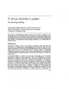
system. However, both two-stage refrigeration and cascade refrigeration systems show the disadvantage of high electricity consumption. To reduce electricity consumption while obtaining a low refrigeration temperature, Fernández–Seara et al. [4] studied a cascade refrigeration system with a CO2 compression system and an NH3/H2O absorption system at an evaporation temperature of -45 °C. This system has a coefficient of performance (COP) of 0.253. Garimella and Brown [5] developed a novel cascade absorption–compression system that coupled a single-effect LiBr/H2O absorption cycle and a subcritical CO2 vapor–compression cycle to generate low-temperature refrigerant (-40 °C) for high-heat-flux electronics used in a naval ship. However, multi-input systems are often unreliable [6]. Therefore, Rogdakis and Antonopoulos [7] studied a NH3/H2O absorption refrigeration system that is merely driven by waste heat. For an ambient temperature of 30 °C, the theoretical COP is in the range of 0.03 to 0.40 when the lowest temperature is in the range of -64 °C to -30 °C. He et al. [8] proposed a novel absorption refrigeration system using R134a and R23 mixed refrigerants and dimethylformamide solvent. The new system used a two-stage absorber in series to reduce the evaporation pressure, and the lowest refrigeration temperature reached -62.3 °C with a COP of 0.023 under a generation temperature of 184.4 °C. In this study, we propose a new absorption–compression refrigeration system for low-temperatures refrigeration based on the cascade utilization of mid-temperature heat source. The energy efficiency boosting mechanism of the proposed system is elucidated. 2. System description The detailed configuration of the new absorption–compression refrigeration system is shown in Fig. 1(a). It comprised a Rankine power subsystem using a mixture working fluid, an absorption subsystem in the high-temperature refrigeration stage, and a single-stage compression subsystem in the low-temperature stage. NH3/H2O solution was used as the working fluid in the power and absorption subsystems, whereas CO2 was used in the compression subsystem. Power Subsystem
Compression refrigeration subsystem (CRS) EVA
23
PC CHEX
PC
4 13 GHEX
27 HRVG 28
REB 20
CON1
6
SUBC
19
LABS (MEVA)
9
3
8 MABS 23
25
ABS
21 10
22 8
HSHE 7
VAL1
LP 21 Absorption refrigeration subsystem (ARS)
2 17
22 VAL2
19
HP 9
15
10
REB
VHEX 5 SHEX 1 1
7 VAL3
27
REC
12 LSUBC
REC
16
12 1
16
CON2
29
2
HP
15
14
VAL2
13 VAL4
14
MSUBC 4
26
17
18
LEVA
11 6
COMP
3
5
25
24
TUR
CON
VAL3
26
MSHE 1
VAL1
24 18
20
MP
Two-stage NH3-H2O absorption refrigeration system
Fig. 1. (a) Schematic of the new absorption–compression refrigeration system; (b) Schematic of the two-stage NH3/H2O refrigeration system
The external heat source (e.g., engine flue gas) successively entered a heat recovery vapor generator (HRVG) and a gas heat exchanger (GHEX). In the Rankine power subsystem, the high-temperature portion of the external heat source was utilized to generate superheated ammonia–water vapor, which expanded across a turbine (TUR) to produce power. In the refrigeration subsystem, the absorption
562
Yi Chen et al. / Energy Procedia 75 (2015) 560 – 565
refrigeration subsystem (ARS) and compression refrigeration subsystem (CRS) operated as hightemperature and low-temperature circuits respectively, and were combined to form a cascade refrigeration system. The two circuits were connected to each other through a cascade heat exchanger (CHEX), which acted as an evaporator for the ARS and a condenser for the CRS. The low-temperature portion of the external heat source and the exhaust vapor of the TUR provided heating loads for the absorption subsystem in GHEX and the reboiler (REB), respectively. The TUR provided the power required by the compressor (COMP) in the CRS. External power was not required, but a mid-temperature heat source for the new system was required. Therefore, this system could be used as a stand-alone unit for refrigeration at low temperatures. A typical two-stage NH3/H2O refrigeration system was selected as the reference system in this study, as shown in Fig. 1(b) [7]. The two-stage system is obtained by adding a low-pressure branch containing one low-pressure evaporator, one low-pressure absorber, two heat exchangers, two throttling devices, and one pump to a conventional single-stage NH3/H2O absorption refrigeration system. 3. System evaluation and simulation 3.1. Evaluation criteria Typical evaluation criteria for refrigeration systems, such as COP and exergy efficiency ηex, were used to evaluate the performance of the proposed system. For this new system, the flue gas was directly discharged to the surroundings after utilization. It is how much cooling capacity could be produced by unit mass of flue gas, rather than COP, that is more concerned and reasonable. Therefore, the cooling capacity per unit mass of flue gas Z was adopted for the system performance evaluation and was expressed as follows: QC (1) Z mf where QC represents the refrigeration output of the compression refrigeration subsystem and mf represents the mass flow rate of flue gas. 3.2. General assumptions and parameters specification In this study, simulations of both the proposed and reference systems were conducted using the commercial software Aspen Plus, which contained various models that could be used for power generation and refrigeration processes. All models were based on mass and energy balance, with a default relative convergence error tolerance of 0.01%. The Predictive Soave-Redlich-Kwong equation of state Table 1. Main assumptions for system simulation was used to calculate the thermodynamic properties of the ammonia–water mixture [9]. The Items Values Peng–Robinson equation of state was used to Pump efficiency (%) 75 calculate the thermodynamic properties of CO2. Turbine isentropic efficiency (%) 85 The STEAM–TA equation of state was used to Minimum exhaust dryness of turbine (%) 90 calculate the thermodynamic properties of H2O. HRVG hot side temperature difference (°C) 30 According to several related studies [10, 11], MITA of HRVG (°C) 15 the parameter specifications are listed in Table 1. MITA of general heat exchangers (°C) 5 Pressure drop from REC to CON (bar) 0.1 The main assumptions for the system simulations Pressure drop from EVA to ABS (bar) 0.2 were as follows: Ammonia mass concentration of the refrigerant (−)
0.998
Yi Chen et al. / Energy Procedia 75 (2015) 560 – 565
(a) The cycle was in steady-state. (b) The general pressure loss is neglected, except for the rectifiers, absorbers, and the throttle valves. The flow crossing the throttle valve process was isenthalpic. (c) Heat loss was ignored. (d) The solution at the outlets of REB, ABS (absorber), and CON (condenser) was based on a saturated state. (e) The isentropic efficiency of CO2 compressor can be expressed in terms of compression ratio Rp [2], as follows: (2) Ks,COMP 0.00476Rp 2 � 0.09238Rp � 0.89810 4. Results and discussion 4.1. System performance The flue gas temperature was usually approximately 350 °C; thus, a TUR inlet temperature of 320 °C was selected with a proper minimum internal temperature approach, and the inlet pressure was 100 bar. The cooling water temperature was 30 °C. The calculations were based on a unit mass flow rate (1 kg/s) of the flue gas fed into the system. Table 2 illustrates the thermodynamic performance of the proposed and reference systems. In the proposed system, heat recovered from the 350 °C flue gas was 226.56 kW, and the refrigeration output was 62.70 kW at an evaporation temperature of -55 °C. The COPt reached 0.277. The cooling capacity per unit mass of flue gas Z was 62.70 kJ/kg. The simulation results for the reference system (derived under the same assumptions) are shown in Table 3. With unit mass flow rate of the flue gas fed into the system, the COPt was 0.185, and�Z was 43.01kJ/kg. The COPt and Z�of the proposed system increased by 49.73% and 45.78% over those of the reference system, respectively. Besides an energy analysis, an exergy analysis was performed to reveal the irreversibility in each process and to show the possibilities and methods for system performance improvement. The results of the exergy analysis are presented in Table 3, and these data indicated where exergy destruction and loss occurred. With the same exergy input (109.32 kW), the exergy outputs of the proposed and reference systems were 21.03 and 14.25 kW, respectively. The exergy efficiency of the proposed system Kex was 21.03%, which was 6.78 percentage points higher than that of the reference system. Exergy destruction and loss in the systems could be divided into four parts. The exergy efficiency enhancement of the proposed system was primarily due to the decrease of exergy destruction and loss in the first part. It included the exergy destruction in the components where working fluids absorb heat from the heat source, such as in HRVG and GHEX of the proposed system and REB of the reference system. The exergy destruction in this part of the Table 2. Thermodynamic performance of the proposed and reference proposed system was 11.38 kW. The exergy systems destruction in this part of the reference system existed in REB and reached 33.83 kW, Proposed Reference which was much higher than that in the Items system system proposed system. Flue gas mass flow rate, mf (kg/s) Thermal energy of flue gas, Qf (kW) Total heat input, QH (kW) Total power input, WP (kW) Cooling energy output, QC (kW) COP of the total system, COPt (−) Cooling capacity per unit mass of flue gas, Z (kJ/kg)
1.00 335.52 226.56 0.00 62.70 0.277
1.00 335.52 232.85 0.81 43.01 0.185
62.70
43.01
4.2. Energy saving mechanism analysis To analyze the heat exchange processes between the working fluids and heat source more intensively, the t-Q diagrams of the heat exchange processes in the proposed and
563
564
Yi Chen et al. / Energy Procedia 75 (2015) 560 – 565
reference systems were performed and compared, as shown in Fig. 2. The heat duty Q was normalized by the thermal energy of Proposed Reference flue gas Qf to show the fraction of the heat Items system system source energy utilized in the system. kW kW In the proposed system [Fig. 2(a)], highExergy input 109.32 109.32 temperature portion of the flue gas heat was Exergy destructions and loss 86.33 93.74 used in HRVG, thereby heating the working 1 Heat exchange processes with heat source 11.38 33.83 fluid in the power subsystem to generate HRVG (REB)* 10.17 33.83 superheated vapor for power generation. GHEX 1.21 2 Heat exchange processes with heat sink 31.65 33.49 Low-temperature portion of the flue gas heat Flue gas loss 15.91 14.20 was absorbed by the NH3/H2O solution in the (Mid-pressure) Absorber 12.49 11.34 absorption refrigeration subsystem to preheat CON2 (CON) 3.25 7.96 the basic solution, resulting in heating load 3 Internal heat exchange processes 23.78 24.32 reduction of the reboiler. The temperature SHEX (HSHE) 3.87 8.77 match between the hot gas and cold fluids (MSHE) 1.14 was well organized by the integration, REB 2.23 resulting in low exergy destruction and loss REC and PC 6.99 6.87 during heat source energy utilization. In the VHEX 3.37 reference system [Fig. 2(b)], mid-temperature (Mid-pressure) Subcooler 0.41 0.24 flue gas was used to directly heat the basic (LSUB) 2.82 solution, and temperature decreased from CHEX 6.91 (MEVA/LABS) 4.48 350 °C to 126 °C, whereas the generation 4 Other components 19.51 2.09 temperature of the two-stage NH3/H2O TUR 4.05 refrigeration system was 150 °C. The exergy COMP 10.51 destruction in REB was significant because of Pumps and valves 4.96 2.09 the serious mismatch in temperatures between Exergy output 22.99 15.58 the hot and cold fluids (with the maximum 21.03 14.25 Exergy efficiency, Kex (%) temperature difference of 200 °C). * The items in ( ) are only for the reference system. Furthermore, the REB in the proposed system used TUR exhaust vapor as heat source, and the heating load of REB was decreased by the heat recovery in GHEX and VHEX (vapor heat exchanger). By choosing a proper TUR back pressure, the exhaust vapor temperature could match the temperature of the solution in REB. In this way, the energy utilization was improved in the proposed system by reducing the exergy destruction and loss. When the quality of the heat source was at the same level, the energy consumption could be reduced. Table 3. Comparison of the exergy distributions in the proposed and reference systems
400
HRVG
350
300
Heat source
250 200
NH3/H2O
150 100 50
REB
350
Temperature �ć
Temperature (ć)
300
400
GHEX
Heat source
250 200 150
NH3/H2O
100 50
Ambient state (25ć)
0
Ambient state (25ć)
0 0.0
0.2
0.4
0.6
0.8
1.0
0.0
0.2
0.4
0.6
0.8
1.0
Fig. 2 t-Q diagrams of the heat exchange process with heat source in the (a) proposed and (b) reference systems
Yi Chen et al. / Energy Procedia 75 (2015) 560 – 565
5. Conclusions A new absorption–compression refrigeration system for freezing application was proposed. In this new system, the cascade use of mid-temperature heat source was implemented. The heat source could be engine flue gas, process waste heat, or solar energy. The proposed system could be used as a stand-alone unit to meet the low-temperature refrigeration load (approximately -55 °C) without additional electricity or power input. For the proposed system, the cooling capacity per unit mass of flue gas was 62.70 kJ/kg, and COP reached 0.277; these values were higher by 45.78% and 49.73%, respectively, than those of the conventional two-stage NH3/H2O absorption refrigeration system. The exergy efficiency in the new system was 20.06%, which was 6.78 percentage points higher than that of the reference system. The energy saving mechanism for the proposed system was recovered through exergy analysis. The temperature match in the heat exchange processes between the working fluids and heat source was improved dramatically. Consequently, the energy utilization was improved. This study may provide a new efficient approach to produce low-temperature cooling energy using mid-temperature heat source. Acknowledgements The authors gratefully acknowledge the support of the National Natural Science Foundation of China (Grant No. 51176185) and the National Basic Research Program of China (Grant No. 2014CB249202). References [1] Fernandez-Seara J, Vales A, Vazquez M. Heat recovery system to power an onboard NH3-H2O absorption refrigeration plant in trawler chiller fishing vessels. Applied Thermal Engineering. 1998;18:1189-205. [2] Lee T-S, Liu C-H, Chen T-W. Thermodynamic analysis of optimal condensing temperature of cascade-condenser in CO2/NH3 cascade refrigeration systems. International Journal of Refrigeration. 2006;29:1100-8. [3] Wu W, Wang B, Shi W, Li X. An overview of ammonia-based absorption chillers and heat pumps. Renewable and Sustainable Energy Reviews. 2014;31:681-707. [4] Fernández-Seara J, Sieres J, Vázquez M. Compression–absorption cascade refrigeration system. Applied Thermal Engineering. 2006;26:502-12. [5] Garimella S, Brown AM, Nagavarapu AK. Waste heat driven absorption/vapor-compression cascade refrigeration system for megawatt scale, high-flux, low-temperature cooling. International Journal of Refrigeration. 2011;34:1776-85. [6] Seyfouri Z, Ameri M. Analysis of integrated compression-absorption refrigeration systems powered by a microturbine. International Journal of Refrigeration-Revue Internationale Du Froid. 2012;35:1639-46. [7] Rogdakis ED, Antonopoulos KA. Performance of a low- temperature NH30H2O absorption-refrigeration system. Energy. 1992;17:477-84. [8] Chen YHZZXGG. Study on a Novel Absorption Referigeration System at Low Cooling. International Refrigeration and Air Conditioning Conference. 2012. [9] ZENG J, YANG J, ZHANG W, HAO M, HAO Z, Lü J. Vapor-liquid equilibrium model for ammonia-water system. Chemical Industry and Engineering Progress. 2010:S2. [10] Han W, Sun L, Zheng D, Jin H, Ma S, Jing X. New hybrid absorption–compression refrigeration system based on cascade use of mid-temperature waste heat. Applied Energy. 2013;106:383-90. [11] Jing X, Zheng D. Effect of cycle coupling-configuration on energy cascade utilization for a new power and cooling cogeneration cycle. Energy Conversion and Management. 2014;78:58-64.
Biography Yi Chen is a graduate student in University of Chinese Academy of Sciences. His major is Engineering Thermophysics. His research is mainly about cogeneration cycles and systems.
565