Contributed Paper
A new approach to the Data Vortex switch architecture Rajat Kumar Singh, Rajiv Srivastava and Yatindra Nath Singh Department of Electrical Engineering, Indian Institute of Technology Kanpur, Kanpur – 208016, INDIA E-mail:
[email protected] 1. INTRODUCTION The architecture of data vortex1 follows the principles of multiple level minimum logic networks interconnect structure2 to explore its high bandwidth and low latency. The data vortex also takes advantage of deflection routing3 technique to resolve the packet contention. The architecture of this switch is cylindrical in shape with multiple layers. The packets may be kept rotating around these cylindrical layers whenever they cannot be directed to the desired port. This paper deals with the modification done in the architecture of data vortex to improve its performance by adding fiber delay lines4,5. The switch is also analyzed by considering all the ports at the innermost cylinders as the distinct output ports. Simulations are done and the results are discussed to elaborate the advantage of modification.
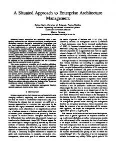
2. DATA VORTEX: AN OVERVIEW The switch architecture (Fig.1) consists of a collection of concentric cylinders which are characterized by height parameter (H) corresponding to the number of ports located along the height of the cylinder. The cylinders are also characterized by angle parameter (A) corresponding to the number of ports along its circumference at a particular height. Third parameter used in this architecture is the number of cylinder (C) which depends upon the height parameter as C = 1 + log2H. The number of ports at each cylinder is HA. At the outermost cylinder these ports are defined as the switch input ports, by considering either all the ports as input (HA, symmetric switch) or a fraction of it (HA', asymmetric switch). Here, A' is the fraction of total number of angle (A) at each height considered as the input port whereas all the angles of this outermost cylinder at that height are still used for routing the packets. At the innermost cylinder1, the assignment of the ports as the output destination was done by selecting only the height information while any of the angular ports at that height can accept the packet destined for that height. All the ports on these cylinders are used to route the packet from the outermost cylinder towards the innermost.
Figure 1. Architecture of Data vortex During every slot, each packet moves one angle forward either along the solid line on the same cylinder or along the dotted line towards the inner cylinder (Fig.1a). The packet moving on a port at the same cylinder (Fig.1b), will choose that port by following the well defined algorithm and the packet moving on a port at the next inner cylinder, will maintain the same height but in both the cases it will be forwarded by an angle. The outermost cylinder performs a filter operation and allows the entry of only limited number of packets through the switch input depending upon the availability of free ports. Once the packet entered into the switch, it will keep on rotating at that particular cylinder until it gets space to move towards the inner cylinder. Thus there was no need of internal buffers at any of the ports.
Photonics 2006
The performance of this switch can be analyzed in terms of two parameters: Injection Ratio (IR) and Mean Hop Count (Average Delay). IR is defined as the ratio of number of successful attempts over the total number of attempts for entering into the switch at the outermost cylinder. Mean hop count is the total number of ports any packet has traveled during its transmission up to the destined output port.
3. DESCRIPTION OF THE MODIFICATION The switch performs well without any use of buffer. The results for the data vortex1 show that the injection ratio (IR) is much better under lower loading condition (Fig.2a). It will be deteriorated heavily at higher loads and this degradation in the IR is more for larger size of switches. Thus to improve the performance of this switch, two modifications are proposed: 1. each angle at the innermost cylinder is treated as distinct output, and 2. addition of extra delay lines at every input port.
3.1.
Each angle at the innermost cylinder is a distinct output
The switch is analyzed by selecting the angle information alongwith height as the destination. Each angle at a particular height on the innermost cylinder will be treated as a distinct output and will accept the packet destined only for it otherwise pass it to the next angular location. Thus the total number of distinct output ports will become HA as compared to H. We have also analyzed the performance of switch considering the asymmetric number of input ports (i.e., HA').
3.1.1. Performance evaluation The results (Fig.2b) indicate that if we consider every port at the innermost cylinder as the distinct output then the IR decreases heavily for switch of smaller heights whereas this decrement is very less for larger heights. Also, increasing the number of output ports affect the performance heavily at higher load. The results shown in Figure 3 discuss the application of asymmetric condition on the switch. We found similar trend of getting lesser IR for modified version (Fig.3b) but the effect of asymmetric condition is still same as compared to the unmodified version. This reduction in IR for switches of higher heights will be compensated by the advantage in
(a) (b) Figure 2. Comparison of IR under symmetrical data for number of output ports equal to (a). H (b). HA
(a) (b) Figure 3. Effect of asymmetries on IR for number of output ports equal to (a). H (b). HA
Photonics 2006
2
terms of having larger number of output ports. Hence there may be a trade-off between the total numbers of destination ports and the reasonable IR.
3.2.
Addition of extra delay lines at every input port
Any incoming packet may get the input port busy due to the routing nature of switch. In such case, the incoming packet will be dropped and results in lowering the IR. Thus the fiber delay lines (FDL) have been added to store those packets, which are going to be lost due to busy input port. These extra delay lines are added to each port at the outermost cylinder only (Fig.4). The length of these delay lines (D) is integral multiple of duration of each time slot which will be equal to the packet length. Since the traffic is probabilistic in nature, so there may be few slots when there will be no arrival at some of the input ports. Those input ports utilize these free slots and consider the packet stored in their corresponding delay lines. While checking for the incoming packets during every slot, each input port scans the delay line first for already stored packet and then it scans the input port for new packet. If there is any stored packet then that port will Figure 4. Modified Data Vortex switch (Top view) consider it for routing and the new incoming packets will be forwarded to the vacant delay line and will be routed in the next slot. Also, any packet at the input port with higher priority will be routed first irrespective of the packet stored in FDL. If any incoming packet finds the input port busy as well as the corresponding FDL is filled completely, then that packet will be dropped.
3.2.1. Performance evaluation The results for injection ratio (IR) and mean hop count (average delay) under different loading condition with and without delay lines (D) are shown (Fig.5). It also compares these parameters for various heights of cylinder. The number of output port is still equal to H as in the actual switch. Here, D = 0 shows the case of data vortex without modification. When we add the extra delay line (D = 1) at each input port, the improvement in IR is better only under lower and moderate loading condition. The IR improvement is more for cylinders of shorter heights as compared to the larger heights. The average delay is more for larger cylindrical heights under moderate loading. The value of D represents the length of delay line in term of time slots. We found that as the height increases, the IR decreases and the advantage in terms of adding extra delay lines is also disappeared (Fig.6a). The effect of asymmetric condition is observed (Fig.6b), but this time the addition of extra delay lines have much better IR for higher heights also. The results for average delay (Fig.7) imply that the addition of delay lines has slight affect on the mean hop count and it remains same under asymmetric condition and under moderate loading condition. Thus we can say that this modification will work properly for cylinders of heights up to H = 128 and under moderate loading condition. Still, under lower loading condition (i.e. ρ ≤ 0.4) we can go for larger heights (Fig.5).
(a) (b) Figure 5. (a). Injection Ratio and (b). Average Delay after adding extra delay line of single slot duration. Straight line: Actual results, Dotted line: Modified results
Photonics 2006
3
(a) (b) Figure 6. Modified results for IR with Height: (a). symmetrical and (b). asymmetrical data
(a) (b) Figure 7. Modified results for Average Delay with Height: (a). symmetrical and (b). asymmetrical data
4. CONCLUSIONS The results indicates that modifications proposed in data vortex switch are feasible and also the switch is scalable under such conditions. Since, the cost of a single fiber of such length will not be too high and will be overshadowed by the advantages we are getting in term of better injection ratio (IR) and average delay.
5. REFERENCES 1
Q. Yang, K. Bergman, G. D. Hughes and F. G. Johnson, J. Lightw. Technol., 19, 1420 (2001). C. Reed, U. S. Patent, 5996020, (1999). 3 I. Chlamtac and A. Fumagalli, IEEE J. Sel. Areas Comm., 11, 550 (1993). 4 R. S. Tucker and W. D. Zhong, IEICE Trans. Comm., E82 B, 254 (1999). 5 D. K. Hunter, M. C. Chia and I. Andonovic, J. Lightw. Technol., 16, 2081 (1998). 2
Photonics 2006
4