A new, continuous-time model for current-mode control (power ...
Recommend Documents
introducing an improvement of the FCS-MPC strategy for a single VSC that is ...... voltage reference. FCS-MPC settings, λd = 0.5 and λu = 1 have been chosen.
instantaneous active and reactive power to control the power converter, the controller ...... Three Level Converters Applied to High Power Wind Turbinesâ IEEE.
May 1, 2012 - Bachelor of Engineering, Computer Engineering. University of Konkuk ... Master of Science Degree in Computer Science. School of Computer ...
May 7, 2014 - 1. Introduction. In nuclear power plants, steam energy is produced in the ... less than 2.5 micrometres reached 993 micrograms per cubic.
Oct 17, 2017 - (BESS) directly into the dc-link of the WEC system without an ...... M.P.; Espinoza, J.R.; Zanchetta, P.; Abu-Rub, H.; Young, H.A.; Rojas, C.A..
command and compressor inlet guide vanes position. ... Key-words: Gas turbine, Identification, ARX, Predictive control, Power plant, ... simplified mathematical model consists of a set of ... in the model used to represent the process and the noise .
Control for Power Electronics. Tobias Geyer, Senior Member, IEEE, and Daniel E. Quevedo, Senior Member, IEEE. AbstractâFor direct model predictive control ...
Key words â Software processes, Embedded systems controls, Automotive, Quality ... Iterative Development Process ... quality is the individual developer's skill,.
Wireless Information Network Laboratory (WINLAB). Dept. of ... from accessing the wireless data network. ... management algorithms for wireless data services.
Simulation tests on a two generator infinite bus power system demonstrate the ... excitation control of each machine is the enhancement of power system ..... Since the electrical power ei. P and the ...... applications on power and drive systems.
of Dynamic Voltage Restorer. A. O. Al-Mathnani, H. Shareef, A. Mohamed, M. A. Mohd Ali, M. A. Hannan. Abstract â This paper presents a new DVR design and ...
In an upshift, clutch L should be released and clutch H should be engaged. Clutch L is ..... when stuck and controllable .... /2/ FORSTER, Hans Joachim.
Feb 17, 2016 - Home Search ... obtained with a commonly used wind farm wake model. 1. ... energies, wind energy is witnessing a continuous growth at an ...
packet-arrival processes, buffering constraints, scheduling policies, as well as QoS ... due to the fact that different sub-carriers of a broadband wireless.
ferent sub-carriers of a broadband wireless system have a strongly .... The instant SNR of sub-carrier s for terminal j at time t is given by v. (t) j,s = ps · (h. (t) j,s)2.
Jul 7, 2014 - Our stage-dependent model is not a spatial model as it ignores the colonization process, since in a greenhouse, we can consider the pest and ...
Nov 18, 2004 - responsibility to manage users' information and the credential of user. Roles assigned .... department administrator, GT is a general teacher, SA standards the school administrator, and GU is .... Published online. November 18 ...
future interdomain routing protocol for optical networks [1â3]. ... a transit provider T that is split into two RCDs,. T1 and T2. .... P(T1, D1), including the list of loose hops: OXC ..... MARCELO YANNUZZI ([email protected]) received a degree.
{roberto.bresin, anders.friberg, sofia.dahl}@speech.kth.se. ABSTRACT. The control of sound synthesis is a well-known problem. This is particularly true if the ...
TWO MODES: SWINGING CRANE AND INVERTED PENDULUM . ...... This tells us that in any mode, the dynamics of the position of the pendulum bob, y , is a.
x0 is the current discrete time instant k and x the next instant k + 1. Further, f (x0) is ... So, using (2), (6) and (7), the transmit power at instant (k + 1) is expressed.
May 16, 2014 - Computational Biology and Bi6~~J:'IIl8tics (M. AkaY,R. Keamey. ..... Steven Anthony; North Carolina State Univ.; ..... Ricardo Luis Armentano" ,Damian Craiem ,Franco Martin Pessana ,Sebastilln Graf, Eduardo De Forteza; ...
Power ElectronicsâPart 1: Algorithm. Tobias Geyer, Senior Member, IEEE and Daniel E. Quevedo, Member, IEEE. AbstractâFor direct model predictive control ...
Index TermsâModel predictive control, power and thermal management ... I. INTRODUCTION. IMPROVING energy system efficiency of mobile and sta- ..... the open circuit voltage determined by the Nernst equation. [17]. The last three terms ...
A new, continuous-time model for current-mode control (power ...
Apr 2, 1991 - URRENT-mode control has been used in switching power. C supplies ... The author is with the Virginia Power Electronics Center, Bradley De-.
IEEE TRANSACTIONS ON POWER ELECTRONICS,
VOL.
27 1
6. NO. 2. APRIL 1991
A New, Continuous-Time Model For Current-Mode Control Raymond B . Ridley
Abstract-The accuracy of sampled-data modeling is combined with the simplicity of pole-zero representation to give a new current-mode control model, accurate to half the switching frequency. All of the small signal characteristics of current-mode control are predicted, including high-frequency subharmonic oscillation which can occur even at duty cycles of less than 0.5. The best representation for the control-to-output transfer function is shown to be third-order. Model predictions are confirmed with measurements on a buck converter.
-E; D
q,,(*A0")
(active) a Icd
I. INTRODUCTION
C
URRENT-mode control has been used in switching power supplies for many years. Numerous attempts have been made to characterize this control system with small-signal models, all with limited degrees of accuracy or usefulness. Some continuous-time models [ 11-[3] provide low-frequency models for the system, but they need to address the well-known phenomenon of current-loop instability as a separate issue. Other models [4]have attempted to explain this instability through a modulator gain model, but predictions are not confirmed by measurements. Conclusions based on this model presented in [SI give misleading information about the design of currentmode systems. Exact discrete-time and sampled-data models [6], [7] can accurately predict responses, but they provide very little design insight due to their complex formulations. In this paper, the accuracy of sampled-data modeling is combined with the simplicity of the model of the three-terminal PWM switch [8] to provide a complete model which accurately predicts characteristics from dc to half the switching frequency. It is shown that an approximation to sampled-data results can provide a simple, accurate model with a finite number of poles. Feedforward gain terms from voltages applied across the inductor during on and off times of the power switch are derived to complete the analysis. Experimental results are presented to confirm the validity of the new model.
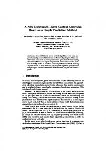
P (passive)
Fig. 1 . PWM three-terminal small-signal switch model. Model can be used for all two-switch PWM converters operating in the continuous conduction mode. Source quantities Vu,,, Z