p-ISSN : 2335-1357
e-ISSN : 2437-1122
Mediterranean Journal of Modeling and Simulation
M
J
M
S
Med. J. Model. Simul. 08 (2017) 001-018
A new hybrid optimization algorithm CRO-DE for optimal coordination of overcurrent relays in complex power systems Mohamed Zellagui
a
, Almoataz Youssef Abdelaziz
b
a
b
Electrical Engineering Department, Faculty of Technology, University of Batna 2, Algeria Electrical Power and Machines Department, Faculty of Engineering, Ain Shams University, Egypt
ARTICLE INFO
ABSTRACT
Article history : Received January 2017 Accepted June 2017
The paper presents a new hybrid global optimization algorithm based on Chemical Reaction based Optimization (CRO) and Di¤erential evolution (DE) algorithm for nonlinear constrained optimization problems. This approach proposed for the optimal coordination and setting relays of directional overcurrent relays in complex power systems. In protection coordination problem, the objective function to be minimized is the sum of the operating time of all main relays. The optimization problem is subject to a number of constraints which are mainly focused on the operation of the backup relay, which should operate if a primary relay fails to respond to the fault near to it, Time Dial Setting (TDS), Plug Setting (PS) and the minimum operating time of a relay. The hybrid global proposed optimization algorithm aims to minimize the total operating time of each protection relay. Two systems are used as case study to check the e¢ ciency of the optimization algorithm which are IEEE 4-bus and IEEE 6-bus models. Results are obtained and presented for CRO and DE and hybrid CRO-DE algorithms. The obtained results for the studied cases are compared with those results obtained when using other optimization algorithms which are Teaching Learning-Based Optimization (TLBO), Chaotic Di¤erential Evolution Algorithm (CDEA) and Modi…ed Di¤erential Evolution Algorithm (MDEA), and Hybrid optimization algorithms (PSO-DE, IA-PSO, and BFOA-PSO). From analysing the obtained results, it has been concluded that hybrid CRO-DO algorithm provides the most optimum solution with the best convergence rate.
Keywords : Complex power systems ; Directional overcurrent relays ; Optimal Coordination ; Chemical reaction based optimization ; Di¤erential evolution algorithm ; Hybrid global optimization algorithm.
c 2017 LESI. All rights reserved.
Nomenclature T Relay total operating time IDM T Inverse De…nite Minimum Time IF Fault current
Email :
[email protected],
[email protected]
1
M. Zellagui et al./ Med. J. Model. Simul. 08 (2018) 001-018
T IDM T IF T DS PS CT CTpr rating Irelay OF T DSmin T DSmax T min T max CT I Tpri cl in Tpri f ar bus Tprimary Tbackup Ncl , Nf ar
Relay total operating time Inverse De…nite Minimum Time Fault current Time Dial Setting Plug Setting Current transformer Primary rating of CT Current seen by the relay Objective function Minimum value for T DS Maximum value for T DS Minimum value of relay operating time Maximum value of relay operating time Coordination Time Interval Operating time to clear near end fault Operating time to clear far end fault Operating time of primary relay Operating time of backup relay Number of relays installed at both ends of the primary
1. Introduction Optimization is the selection of the best element from some sets of variables with a long history dating back to the years when Euclid conducted research to gain the minimum distance between a point and a line. When the complexity and the dimension of the search space make a problem unsolvable by a deterministic algorithm, probabilistic algorithms deal with this problem by going through a diverse set of possible solutions or candidate solutions. Over the past years, there has been a growing interest in solving optimization problems by means of algorithms inspired on natural paradigms. These techniques have been applied to the optimization of complex computational problems in the engineering problems. Global optimization is a branch of applied mathematics and numerical analysis that deals with the global optimization of a function or a set of functions according to some criteria. Typically, a set of bound and more general constraints is also present, and the decision variables are optimized considering also the constraints. Directional overcurrent relay is a good technical and economic choice for protection of transmission and distribution power systems [1]. Such a relay with inverse time characteristics consists of an instantaneous unit and a time overcurrent unit. The overcurrent relay has two parameters to be de…ned which are PS and TDS. The use of computers in the power systems application of relay coordination has relieved protection engineers from huge mathematical calculations. Coordination of overcurrent relays requires the accurate selection of optimum settings. Out of both, only the values of TDS can be optimized while solving the coordination problem with the help of optimization algorithms. In protection coordination problem, the total operating time of all main relays is minimized. 2
M. Zellagui et al./ Med. J. Model. Simul. 08 (2018) 001-018
Constraints of the problem are considered in the secondary relay which should operate if the main relay fails to respond to the fault near to it, TDS and PS and minimum operating time of the relay. Table 1 represents the di¤erent optimization algorithms which were developed by researchers to provide optimum solution for relay settings and coordination in order to achieve optimum protection. Table 1 –Literature for global optimization algorithm. Paper [2] [3] [4] [5] [6] [7-8] [9] [10] [11] [12] [13] [14] [15] [16] [17] [18] [19] [20] [21] [22] [23]
Optimization Algorithm Evolutionary Algorithm Di¤erential Evolution Algorithm Modi…ed Di¤erential Evolution Algorithm Self-Adaptive Di¤erential Evolutionary Particle Swarm Optimization Modi…ed Particle Swarm Optimization Evolutionary Particle Swarm Optimization Box-Muller Harmony Search Zero-one Integer Programming Covariance Matrix Adaptation Evolution Strategy Seeker Algorithm Teaching Learning Based Optimization Chaotic Di¤erential Evolution Algorithm Informative Di¤erential Evolution Algorithm Fire‡y Optimization Algorithm Krill Herd Algorithm Non-dominated Sorting Genetic Algorithm Biogeography Based Optimization Hybrid IA-PSO Algorithm Hybrid BFOA-PSO Algorithm Hybrid PSO-DE Algorithm
In this research work, a hybrid global optimization technique namely CRO-DE is proposed to select the optimal values of relay settings and present a solution for the coordination problem between primary and backup relays. In this paper, hybrid CRO-DE algorithms are applied to IEEE 4-bus and IEEE 6-bus systems which are modelled and simulated to verify the e¢ ciency of the proposed hybrid algorithm. Moreover, the obtained results when using these three algorithms are compared with the published results obtained for TLBO, CDEA, MDEA, hybrid PSO-DE, hybrid IA-PSO, and hybrid BFOA-PSO optimization algorithms. When compared with the other algorithms, hybrid CRO-DE algorithm shows faster convergence and provides an improvement in minimizing the total operating time (T ) of each protection relay in the two studied cases. 2. Optimal Relay Coordination Problem The operating time of IDMT relay is inversely proportional to the fault current. Hence, overcurrent relay will operate fast after sensing a high current. The tripping time of the 3
M. Zellagui et al./ Med. J. Model. Simul. 08 (2018) 001-018
relay follows a time over current delayed curve, in which the time delay depends upon the current. The two decisive factors are T DS and P S. The operating time of the relay is closely related to T DS, P S and the fault current (IF ). The total operating time is given by a non-linear mathematical equation [3], [11-15] with respect to the coordination time constraint between backup and primary relays : T DS
T = IF P S CTpr
(1)
rating
Where, , and are constants. According to IEEE standards [21], the values of these constants are given by 0.14, 0.02 and 1.0, respectively. IF is the fault current at CT primary terminal where the fault occurs while CTpr rating is the primary rating of CT . The ratio between IF and CTpr rating gives the current seen by the relay denoted by Irelay . Irelay =
IF CTpr
(2)
rating
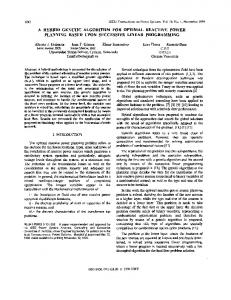
2.1. Objective Function As in Figure 1, a close-in fault (or near end fault) is a fault that occurs close to the relay and a far-bus fault (or far end fault) is a fault that occurs at the other end of the line.
Fig. 1 –Close-in and far-bus faults for primary relay. In coordination studies, the summation of the operating time of all the primary relays to clear a near or far end fault can be considered as an objective function that is to be minimized. Therefore, the objective function (OF) can be expressed as follows, as given in [4], [14-15] : M inimizeOF =
Ncl X
Nf ar i Tpri cl in
+
i=1
X
j Tpri
f ar bus
(3)
j=1
Where, i Tpri
cl in
0:14
= P Si
i IF i CTpr
T DS i
(4)
0:02
1 rating
4
M. Zellagui et al./ Med. J. Model. Simul. 08 (2018) 001-018
j Tpri
f ar bus
T DS j
0:14
=
j P S j CTpr
(5)
0:02
j IF
1 rating
2.2. Constraints Three constraints are considered for the minimization problem. The …rst constraint is T DS of the relay which is the time delay before the relay operates whenever the fault current becomes equal to or greater than the P S setting [12-17]. i T DSmin
T DS i
i T DSmax
(6)
i i are the minimum and maxiand T DSmax Where, i varies between 1 and Ncl . T DSmin mum limits of T DS which are 0.05 and 1.10 sec, respectively. The second constraint concerning P S takes the form :
P Si
i P Smin
i P Smax
(7)
i i Where, i varies between 1 and Nf ar . P Smin and P Smax are the minimum and maximum values of P S which are 1.25 and 1.50, respectively. Relay operating time is related to the fault current which can be seen by the relay and the pickup current setting. Relay operating time is based on the type of the relay and it can be determined by standard characteristic curves of the relay or analytic formula. Hence, the relay operating time is de…ned by :
Timin
Ti
Timax
(8)
Where, T min and T max are the minimum and maximum values for the relay operating time which are 0.05 and 1.00, respectively. The coordination time interval between the primary and the backup relays must be veri…ed during the optimization procedure. In this paper, the chronometric coordination between the primary and the backup relays is used : Tbackup
Tprimary
CT I
Where, Tbackup and Tprimary are the operating time of the backup and primary relay, respectively and CT I is the minimum coordination time interval. For electromechanical relays, CT I varies between 0.30 and 0.40 sec, while for numerical relays CT I varies between 0.10 and 0.20 sec [13-14]. The value of Tbackup and Tprimary can be determined by equations (10) and (11) respectively. i Tbackup
T DS x
0:14
= P Sx
i IF i CTpr
1 rating
0:14
i Tprimary = P Sy
(9)
0:02
i IF i CTpr
T DS y
(10)
0:02
1 rating
5
M. Zellagui et al./ Med. J. Model. Simul. 08 (2018) 001-018
3. Hybrid Global Optimization Algorithms (CRO-DE) Mutation operation of Di¤erential Evolution (DE) algorithm is integrated with intermolecular ine¤ective collision and crossover operation is introduced in the inter-molecular collision, synthesis, and decomposition process to accelerate the convergence speed and improve the solution quality of Chemical Reaction Optimization (CRO) algorithm. 3.1. Chemical Reaction based Optimization (CRO) In the year of 2011, authors in [24-26] proposed CRO algorithm, based on chemical reaction process where molecules undergo a sequence of reactions with each other. The CRO has good searching ability that shows excellent operation of intensi…cation and diversi…cation which are two important features of evolutionary algorithm. In CRO, atomic structure of molecule represents a solution of the optimization problem. Potential energy (PE) and kinetic energy (KE) are two key factors for a molecule. The …tness of a solution is judged by the PE energy of the molecule, while KE is used to control the acceptance of new solutions with worse …tness. Chemical reaction process may be classi…ed into four di¤erent categories namely (i) reactions are on-wall ine¤ective collision, (ii) decomposition, (iii) inter-molecular ine¤ective collision and (iv) synthesis. On-wall ine¤ective collision and decomposition reactions are of single molecular reactions, where as inter-molecular ine¤ective collision and synthesis reaction are of the later category [24]. (i) On-wall ine¤ective collision The on-wall ine¤ective collision reaction occurs when a molecule hits the wall and then bounces back. In this reaction, a molecule ms is allowed to change to another molecule ms1 if the following condition is satis…ed : Ekms + Epms
Epms1
(11)
(ii) Decomposition The decomposition reaction is used to mimic the process of hitting the wall and then decomposing into two or more pieces. Because of the severe collision, the resultant molecular structure of the two newly formed molecules ms1, ms2 are entirely di¤erent from the original molecule ms and is also di¤erent from the neighborhood molecules. In decomposition process takes place if. Ekms + Epms
Epms1 + Epms2
(12)
(iii) Inter-molecular ine¤ective collision The inter-molecular ine¤ective collision mimics the process that two molecules ms1, ms2 collide with each other and generate two new molecules ms01, ms02. As the collision is not severe, the molecular structures of the generated molecules are closer to the original molecules. Inter-molecular ine¤ective collision occurs if. Ekms1 + Epms1 + Ekms2 + Epms2
0
0
Epms1 + Epms2
(iv) Synthesis collision 6
(13)
M. Zellagui et al./ Med. J. Model. Simul. 08 (2018) 001-018
In this process, two molecules ms1, ms2 collides and combines together to form a single molecule ms01. The molecular structure of the newly formed molecule is entirely di¤erent from the molecular structure of original molecules. The condition or synthesis collision is as follows. Ekms1 + Epms1 + Ekms2 + Epms2
Epms
0
(14)
3.2. Di¤erential Evolution (DE) DE is a population based meta-heuristic algorithm, capable of handling non-di¤erentiable, non-linear and multi-modal objective functions [27]. A brief description of di¤erent steps of DE algorithm is given below [28, 29] : (i) Initialization In this process, a population of individuals is randomly initialized where each individual represents a potential solution to the problem. The individual vectors are randomly initialized as follows : xji = xjmin + rand
xjmax
xjmin
(15)
(ii) Mutation In this process, the individual vectors mutate with each other to form donor vectors. For each target vector xji , donor vector vij is de…ned by : vij = xjk + F
xjm
xjn
(16)
Where, xjk ; xjm ; xjn are three randomly target vectors of the current population and F is a positive control parameter used for scaling the di¤erence vectors. (iii) Crossover In crossover, the parent vector is mixed with the mutated vector to create a trial vector, according to the following equation : uji =
vij if randi;j xji else
cr
(17)
Where, cr is the crossover probability and randi;j is a random number between [0, 1]. (iv) Selection In this process, a competition is carried out between each individual Xi and its o¤spring Ui and the winner, selected deterministically based on …tness values, is promoted to the next generation. The selection operation can be expressed as follows : Xi (t + 1) =
Ui (t) if f (Ui (t)) Xi (t) else
f (Xi (t))
(18)
And, Ui = ui1 ; ui2 ; :::; uij ; :::; uid
(19)
7
M. Zellagui et al./ Med. J. Model. Simul. 08 (2018) 001-018
Xi = xi1 ; xi2 ; :::; xij ; :::; xid
(20)
Where, f (x) is the objective function to be minimized and d is the number of control variables.
3.3. Hybrid CRO-DE Algorithm The CRO algorithm that emphasizes on exploring the entire search space and a local version of DE algorithm that emphasizes on exploiting the local search space are combined together to make an impact on the performance of the algorithm in terms of the solution quality and convergence speed [30, 31]. The general step of the HCRO algorithm is summarized as follows [31] : Step 1 : Initialize several numbers of molecules by randomly generated molecular structure depending upon the population size. The molecular structure of each molecule represents a potential solution to the given problem. Step 2 : The …tness values of the speci…c problem of the population are assigned as the potential energy (PE) of the individual molecule. A random kinetic energy (KE) is set to the di¤erent molecules. Step 3 : Based on the PE values (…tness values) best solutions are retained by elite molecules. Step 4 : The non-elite molecules are modify using on-wall ine¤ective collision operations as described below : Step 4.1 : One molecule ms is selected randomly. Step 4.2 : Using the mutation operation of DE (described in Section ‘Di¤erential evolution’) new molecule ms1 is generated which may mathematically be expressed as : ms1 = msk + f
(msm
(21)
msn )
Where, msk , msm , msn are the three di¤erent molecules chosen randomly from the current population. Step 4.3 : The potential energy Epms1 of the molecule ms1 is evaluate and the old molecule ms is replaced by new one ms1 if the condition Ekms + Epms Epms1 is satis…ed and the KE of the molecule ms1 is evaluated by : Ekms1 = rand (0; 1)
Ekms + Epms
Epms1
(22)
Step 5 : Decomposition operation is performed to modify the molecular structure of the molecules by the following steps : Step 5.1 : Two molecules, one molecule ms from the population and another randomly generated molecule ms1 are selected for decomposition operation. Step 5.2 : Crossover operation of DE is applied on ms and ms1 to generate two new molecules ms0 and ms"2 Step 5.3 : Potential energy Epms0 and Epms01 of molecules ms0 and ms01 are evaluated. If, Ekms + Epms Epms0 + Epms01 molecule ms are deleted and the molecules ms0 and ms01 are pushed into the population. Modify the KE of ms0 and ms01 as below : 8
M. Zellagui et al./ Med. J. Model. Simul. 08 (2018) 001-018
0
Ekms = rand (0; 1) 0
ms1
Ek
= [1
h
Ekms + Epms
rand (0; 1)]
h
Epms
0
0
Epms1
i
(23) 0
0
Epms + Epms1
Ekms + Epms
i
(24)
Step 6 : Inter-molecular ine¤ective collisions are made to modify the molecular structure each molecule using the following steps : Step 6.1 : Randomly select two molecules ms1 and ms2 from the population. Step 6.2 : Two new molecules ms11 and ms21 are generated using crossover operation of DE by equation (18). Step 6.3 : Evaluate potential energy Epms1 and Epms2 of molecules ms11 and ms21 and replace molecules ms1 and ms2 by molecules ms11 and ms21 , respectively. The KE of the molecules ms1 and ms2 are evaluated using " ms1 # ms1 ms2 ms2 + E + E + E E 1 p p k k ms (25) Ek 1 = rand (0; 1) ms1 ms2 Ep 1 + Ep 1 ms1 Ek 1
= [1
rand (0; 1)]
"
1
1
Epms + Ekms + Epms +Ekms
ms11
2
Ep
2
ms21
+ Ep
#
(26)
Step 7 : Synthesis collision operation are performed to update the molecular structure of the molecules using the following steps : Step 7.1 : Two molecules ms1 and ms2 are randomly selected from the population set. Step 7.2 : Apply the conventional cross over operation of GA on ms1 and ms2 by considering them as parents’chromosomes and generate a child chromosome ms11 . Step 7.3 : Evaluate Epms1 of the molecule ms11 . The molecules ms1 and ms2 are omitted and the molecule ms11 is push into the population if Ekms1 + Epms1 + Ekms2 + Epms2 Epms1 .The KE of the new molecule ms11 is calculated using : h i 1 1 2 2 1 ms1 Ek 1 = rand (0; 1) Ekms + Epms + Ekms + EPms Epms1 (27)
Step 8 : The feasibility of a problem solution is veri…ed and the infeasible solutions are replaced by feasible solution set. Step 9 : The updated molecules are sorted. Step 10 : The best elite molecules are replaced by the worst molecule. Step 11 : The processes of generating new molecules and selecting those with better function values are continued until the given stopping conditions are satis…ed. The iteration process can be stopped after a …xed number of generations or when any signi…cant improve improvement in the solution does not occur. 4. Case Study and Simulation Results
The optimization algorithms CRO, DE and hybrid CRO-DE are validated and tested on two systems, namely IEEE 4-bus and IEEE 6-bus models as shown in Figures 2.a and 2.b, respectively. The …rst case study consists of two power generators, four lines and 9
M. Zellagui et al./ Med. J. Model. Simul. 08 (2018) 001-018
eight IDMT directional overcurrent relays. The objective of the optimization problem in this case is to coordinate the settings of eight relays. Accordingly, there are 16 decision variables which are T DS 1 to T DS 8 and P S 1 to P S 8 . The second case study consists of three power generators, seven lines and fourteen directional overcurrent relays [15-23]. The objective of the optimization problem in this case is to coordinate the settings of fourteen relays. Accordingly, there are 28 decision variables which are T DS 1 to T DS 14 and P S 1 to P S 14 . CT I is selected to take the value of 0.30 sec in each of the studied cases.
Fig. 2 –Case study systems : (a) IEEE 4-bus, (b) IEEE 6-bus. For each case study, the values used for IF and CTpr_rating are listed in Tables 2 and 3 such that the data related to TPi ri f ar bus and TPj ri f ar bus are shown in Table II, while y x are shown in Table 2. the data related to Tbackup and Tprimary Table 2 –IF and CTpr
rating
j i and Tpri_f for Tpri_cl_in ar_bus in case study.
(a). IEEE 4-bus
TDSi T DS 1 T DS 2 T DS 3 T DS 4 T DS 5 T DS 6 T DS 7 T DS 8
Tipri_cl_in IiF CTipr rating 20.32 0.4800 88.85 0.4800 13.60 1.1789 116.81 1.1789 116.70 1.5259 16.67 1.5259 71.70 1.2018 19.27 1.2018
10
TDSj T DS 2 T DS 1 T DS 4 T DS 3 T DS 6 T DS 5 T DS 8 T DS 7
Tjpri_f ar_bus IjF CTjpr rating 23.75 0.4800 12.48 0.4800 31.92 1.1789 10.38 1.1789 12.07 1.5259 31.92 1.5259 11.00 1.2018 18.91 1.2018
M. Zellagui et al./ Med. J. Model. Simul. 08 (2018) 001-018
(b). IEEE 6-bus
TDSi T DS 1 T DS 2 T DS 3 T DS 4 T DS 5 T DS 6 T DS 7 T DS 8 T DS 9 T DS 10 T DS 11 T DS 12 T DS 13 T DS 14
Tipri_cl_in IiF CTipr rating 2.5311 0.2585 2.7376 0.2585 2.9723 0.4863 4.1477 0.4863 1.9545 0.7138 2.7678 0.7138 3.8423 1.7460 5.6180 1.7460 4.6538 1.0424 3.5261 1.0424 2.5840 0.7729 3.8006 0.7729 2.4143 0.5879 5.3541 0.5879
Table 3 –IF and CTpr
rating
TDSj T DS 2 T DS 1 T DS 4 T DS 3 T DS 6 T DS 5 T DS 1 T DS 2 T DS 3 T DS 4 T DS 5 T DS 6 T DS 1 T DS 2
Tjpri_f ar_bus IjF CTjpr rating 5.9495 0.2585 5.3752 0.2585 6.6641 0.4863 4.5897 0.4863 6.2345 0.7138 4.2573 0.7138 6.3694 1.7460 4.1783 1.7460 3.8700 1.0424 5.2696 1.0424 6.1144 0.7729 3.9005 0.7729 2.9011 0.5879 4.3350 0.5879
y x for Tbackup and Tprimary in case study.
(a). IEEE 4-bus Txbackup Relay No: IF i 5 20.32 5 12.48 7 13.61 7 10.38 1 116.81 2 12.07 2 16.67 4 11.00 4 19.27
Typimary Relay No: IF j 1 20.32 1 12.48 3 13.61 3 10.38 4 116.81 6 12.07 6 16.67 8 11.00 8 19.27
CTipr rating 1.5259 1.5259 1.2018 1.2018 0.4800 0.4800 0.4800 1.1789 1.1789
11
CTjpr rating 0.4800 0.4800 1.1789 1.1789 1.1789 1.5259 1.5259 1.2018 1.2018
M. Zellagui et al./ Med. J. Model. Simul. 08 (2018) 001-018
(b). IEEE 6-bus Txbackup Relay No: IF i 8 4.0909 11 1.2886 8 2.9323 3 0.6213 3 1.6658 10 0.0923 10 2.5610 13 1.4995 1 0.8869 1 1.5243 12 2.5444 12 1.4549 14 1.7142 3 1.4658 3 1.1231 11 2.1436 2 2.0355 11 1.9712 2 1.8718 13 1.8321 4 3.4386 13 1.6180 4 3.0368 14 2.0871 6 1.8138 14 1.4744 6 1.1099 8 3.3286 2 0.4734 8 4.5736 2 1.5432 12 2.7269 6 1.6085 12 1.8360 10 2.0260 4 0.8757 10 2.7784 4 2.5823
Typimary Relay No: IF i 1 5.3752 1 5.3752 1 2.5311 2 2.7376 2 5.9495 3 4.5897 3 2.9723 3 4.5897 4 4.1477 4 6.6641 5 4.2573 5 1.9545 5 4.2573 6 6.2345 6 6.2345 7 4.1783 7 4.1783 7 3.8423 7 3.8423 9 5.2696 9 5.2696 9 4.6538 9 4.6538 11 3.9005 11 3.9005 11 2.5840 11 2.5840 12 3.8006 12 3.8006 12 6.1144 12 6.1144 13 4.3350 13 4.3350 13 2.4143 14 2.9011 14 2.9011 14 5.3541 14 5.3541
CTipr rating 1.7460 0.7729 1.7460 0.4863 0.4863 1.0424 1.0424 0.5879 0.2585 0.2585 0.7729 0.7729 0.5879 0.4863 0.4863 0.7729 0.2585 0.7729 0.2585 0.5879 0.4863 0.5879 0.4863 0.5879 0.7138 0.5879 0.7138 1.7460 0.2585 1.7460 0.2585 0.7729 0.7138 0.7729 1.0424 0.4863 1.0424 0.4863
CTjpr rating 0.2585 0.2585 0.2585 0.2585 0.2585 0.4863 0.4863 0.4863 0.4863 0.4863 0.7138 0.7138 0.7138 0.7138 0.7138 1.7460 1.7460 1.7460 1.7460 1.0424 1.0424 1.0424 1.0424 0.7729 0.7729 0.7729 0.7729 0.7729 0.7729 0.7729 0.7729 0.5879 0.5879 0.5879 0.5879 0.5879 0.5879 0.5879
Further details on the values of the parameters used for each of the proposed algorithm 12
M. Zellagui et al./ Med. J. Model. Simul. 08 (2018) 001-018
CRO-DE are mentioned in the Appendix. 4.1. Simulation Results and Comparison Figures 3.a and 3.b represent the convergence characteristics of the hybrid CRO-DE optimization algorithm when applied to complex power systems IEEE 4-bus and IEEE 6-bus systems, respectively.
Fig. 3 –Convergence characteristics of CRO-DE in case study : (a) IEEE 4-bus, (b) IEEE 6-bus. 4.2. Optimal Relay Settings The new optimal relays settings (T DS and P S) for each relay in the two studied cases are obtained using hybrid CRO-DE algorithms and presented in Table 4. Table 4 –Optimal relays settings. (a). IEEE 4-bus Relay No: 1 2 3 4 5 6 7 8
TDS 0.0371 0.2414 0.0460 0.1730 0.1323 0.0567 0.1542 0.0523
13
PS 1.4582 1.6151 1.3322 1.6172 1.6174 1.4304 1.7165 1.4311
M. Zellagui et al./ Med. J. Model. Simul. 08 (2018) 001-018
(b). IEEE 6-bus Relay No: 1 2 3 4 5 6 7 8 9 10 11 12 13 14
TDS 0.4137 0.7523 0.3853 0.4462 0.2123 0.4112 0.2041 0.2176 0.3011 0.2245 0.2612 0.1039 0.2133 0.2712
PS 0.4767 0.4711 0.4145 0.4767 0.4112 0.3476 0.4120 0.4134 0.3176 0.4701 0.4622 0.4721 0.4542 0.3071
4.3. Optimal CTI Optimal CT I, between the backup and primary overcurrent relays, is calculated using the obtained optimum values of T DS and P S for each of the two studied cases when using MDEA, TLBO algorithms, and hybrid CRO-DE optimization algorithm, as shown in Table 5. From Table 5, it is observed that hybrid CRO-DE optimization algorithm generally gives minimum CTI values when compared with those obtained when using other optimization algorithms. Table 5 –Optimal CTI value. (a). IEEE 4-bus Relay No: MDEA [4] 1 4 0.3001 2 6 0.3482 2 6 0.2990 4 8 0.3972 4 8 0.2996 5 1 0.2995 5 1 0.4008 7 3 0.2993 7 3 0.3491
TLBO [14] 0.5318 0.6439 0.6004 0.5105 0.4327 0.3003 0.3562 0.3551 0.3826
14
CRO DE 0.3012 0.3116 0.3242 0.3225 0.3137 0.3043 0.3271 0.3158 0.3102
M. Zellagui et al./ Med. J. Model. Simul. 08 (2018) 001-018
(b). IEEE 6-bus Relay No: MDEA [4] 8 1 0.2881 11 1 4.0293 8 1 0.8068 3 2 1669.6 3 2 0.1999 10 3 -0.1812 10 3 0.3780 13 3 0.3003 1 4 0.4583 1 4 0.1998 12 5 0.2257 12 5 0.8392 14 5 0.5192 3 6 0.5781 3 6 0.3479 11 7 0.2001 2 7 0.2380 11 7 0.2371 2 7 0.2000
TLBO [14] 2.1885 1.5348 3.2497 2.2012 0.4382 0.4182 1.2362 0.3079 0.8437 0.5170 0.9375 1.5253 1.1805 0.5510 0.3001 1.3738 0.9828 1.4725 1.0195
CRO DE 0.3181 0.3185 0.3777 0.3266 0.3779 0.3728 0.3025 0.3278 0.3183 0.4194 0.3196 0.3075 0.3472 0.3177 0.3076 0.3171 0.3297 0.3003 0.3010
4.4. Comparing Results Table 6 presents the minimum values of the objective function which are obtained when using hybrid CRO-DE algorithm for each case study. It also shows the published results of the minimum objective function values for other optimization algorithms. Table 6 –Objective function comparison for case study. (a). IEEE 4-bus Algorithm TLBO [14] MDEA [4] CDEA [15] PSO-DE [23] IA-PSO [21] BFOA-PSO [22] CROA-DE
(b). IEEE 6-bus
OF (sec) 5.5890 3.6674 3.6774 3.4293 3.1239 3.1129 2.9731
Algorithm TLBO [14] CDEA [15] MDEA [4] BFOA-PSO [22] PSO-DE [23] IA-PSO [21] CROA-DE
OF (sec) 23.7878 10.6272 10.3514 9.4371 9.2671 7.6722 7.1463
When comparing the objective function values given in Table 6, it can be seen that proposed hybrid CRO-DE algorithm suggested algorithm gives better performance and o¤ers the best solution. This is represented in providing the minimum objective function value when compared with those results obtained when using other optimization algo15
M. Zellagui et al./ Med. J. Model. Simul. 08 (2018) 001-018
rithms. This proves the validity of the proposed hybrid algorithm in relays coordination for complex power systems. 5. Conclusion In this paper, hybrid global optimization algorithm, namely CRO-DE algorithm, was presented to solve the coordination problem of directional overcurrent relays. The proposed global optimization algorithm was validated and tested on two complex power system models. Though the three algorithms showed better results than those obtained in literature for other optimization algorithms, such as TLBO, CDEA and MDEA, robustness and feasibility of hybrid CRO-DE algorithm were clearly observed in the obtained results. Based on the obtained simulation results, CRO-DE in particular proved its superiority in providing the minimum operating time T of relays at a fast convergence rate as well as securing minimum coordination time interval between primary and backup relays in complex power systems. This was achieved through …nding the optimum settings relays T DS and P S values of each relay. The advantages encountered when using hybrid CRO-DE algorithm are attributed to its hybrid nature which combines the immune information processing mechanism and the particle swarm optimization algorithm to achieve better and fast solution. Therefore, it is recommended to use the proposed hybrid CRO-DE algorithm as an e¢ cient hybrid optimization algorithm in the coordination of directional overcurrent relays. REFERENCES [1] D. Birla, R.P. Maheshwari, and H.O. Gupta, “An Approach to Tackle the Threat of Sympathy Trips in Directional Overcurrent Relay Coordination”, IEEE Transactions on Power Delivery, Vol. 22, No. 2, pp. 851-858, 2007. [2] J.A. Sueiro, E. Diaz-Dorado, E. Míguez, and J. Cidrás, “Coordination of Directional Overcurrent Relay using Evolutionary Algorithm and Linear Programming”, International Journal of Electrical Power and Energy Systems, Vol. 42, pp. 299-305, 2012. [3] R. Thangaraj, T. R. Chelliah, and M. Pant, “Overcurrent Relay Coordination by Differential Evolution Algorithm”, IEEE International Conference on Power Electronics, Drives and Energy Systems, India, December 16-19, 2012. [4] R. Thangaraj, M. Pant, and K. Deep, “Optimal Coordination of Overcurrent Relays using Modi…ed Di¤erential Evolution Algorithms”, Engineering Applications of Arti…cial Intelligence, Vol. 23, pp. 820-829, 2010. [5] M. Mohseni, A. Afroomand, and F. Mohsenipour, “Optimum Coordination of Overcurrent Relays Using SADE Algorithm”, 16th IEEE Conference on Electrical Power Distribution Networks, Bandar Abbas, Iran, 19-20 April, 2011. [6] M.R. Asadi, and S.M. Kouhsari, “Optimal Overcurrent Relays Coordination using Particle Swarm Optimization Algorithm , IEEE/PES Power Systems Conference and Exposition, Seattle, USA, 15-18 March, 2009. [7] H. Zeineldin, E. El-Saadany, and M. Salama, “Optimal Coordination of Overcurrent Relays using a Modi…ed Particle Swarm Optimization”, Electrical Power Systems Research, Vol. 76, No. 11, pp. 988-995, 2006. 16
M. Zellagui et al./ Med. J. Model. Simul. 08 (2018) 001-018
[8] M.M. Mansour, S.F. Mekhamer, and N.E.S. El-Kharbawe, “A Modi…ed Particle Swarm Optimizer for the Coordination of Directional Overcurrent Relays”, IEEE Transactions on Power Delivery, Vol. 22, No. 3, pp. 1400-1410, 2007. [9] H. Leite, J. Barros, and V. Miranda, “The Evolutionary Algorithm EPSO to Coordinate Directional Overcurrent Relays”, 10th IET International Conference on Developments in Power System Protection, Manchester, United Kingdom, March 29 - April 1, 2010. [10] A. Fetanat, G. Sha…pour, and F. Ghanatir, “Box-Muller Harmony Search Algorithm for Optimal Coordination of Directional Overcurrent Relays in Power System”, Scienti…c Research and Essays, Vol. 6, No. 19, pp. 4079-4090, 2011. [11] J. Moirangthem, S.S. Dash, and R. Ramaswami, “Zero-one Integer Programming Approach to Determine the Minimum Break Point Set in Multi-loop and Parallel Networks”, Journal of Electrical Engineering & Technology, Vol. 7, No. 2, pp. 151-156, 2012. [12] M. Singh, B. K. Panigrahi, and R. Mukherjee, “Optimum Coordination of Overcurrent Relays using CMA-ES Algorithm”, IEEE International Conference on Power Electronics, Drives and Energy Systems, Bengaluru, India, 16-19 December, 2012. [13] T. Amraee, “Coordination of Directional Overcurrent Relays Using Seeker Algorithm”, IEEE Transactions on Power Delivery, Vol. 27, pp. 1415-1422, 2012. [14] M. Singh, B.K. Panigrahi, A.R. Abhyankar, “Optimal Coordination of Directional Overcurrent Relays using Teaching Learning-Based Optimization (TLBO) Algorithm”, International Journal of Electrical Power and Energy Systems, Vol. 50, pp. 33-41, 2013. [15] T. R. Chelliah, R. Thangaraj, S. Allamsetty, and M. Pant, “Coordination of Directional Overcurrent Relays using Opposition based Chaotic Di¤erential Evolution Algorithm”, International Journal of Electrical Power and Energy Systems, Vol. 55, pp. 341-350, 2014. [16] M. Singh, B.K. Panigrahi, A.R. Abhyankar, and S. Das, “Optimal Coordination of Directional Over-current Relays using Informative Di¤erential Evolution Algorithm”, Journal of Computational Science, Vol. 5, pp. 269-276, 2014. [17] R. Benabid, M. Zellagui, A. Chaghi, and M. Boudour, “Application of Fire‡y Algorithm for Optimal Directional Overcurrent Relays Coordination in the Presence of IFCL”, International Journal of Intelligent Systems and Applications, Vol. 6, No. 2, pp. 44-53, 2014. [18] M. Zellagui, and A. Chaghi, “Application KHA for Optimal Coordination of Directional Overcurrent Relays in the Presence Multi GCSC", ACTA Technica Corviniensis, Tome VIII, pp. 61-67, 2015. [19] Z. Moravej, F. Adelnia, and F. Abbasi, “Optimal Coordination of Directional Overcurrent Relays using NSGA-II”, Electric Power Systems Research, Vol. 119, pp. 228-236, 2015. [20] M. Zellagui, R. Benabid, M. Boudour, and A. Chaghi, “Optimal Overcurrent Relays Coordination in the Presence Multi TCSC on Power Systems Using BBO Algorithm”, International Journal Intelligent Systems and Applications, Vol. 7, No. 2, pp. 13-20, 2015. [21] M. Zellagui, and H.A. Hassan, “A Hybrid Optimization Algorithm (IA-PSO) for Op17
M. Zellagui et al./ Med. J. Model. Simul. 08 (2018) 001-018
timal Coordination of Directional Overcurrent Relays in Meshed Power Systems", WSEAS Transactions on Power Systems, Vol. 10, pp. 240-250, 2015. [22] H.A. Hassan, and M. Zellagui, “Optimal Coordination of Directional Overcurrent Relays Using Hybrid BFOA-PSO Optimization Algorithm", Electrotehnica, Electronica, Automatica, Vol. 63, No. 2, 116-125, 2015. [23] M. Zellagui, and A.Y. Abdelaziz, "Optimal Coordination of Directional Overcurrent Relays using Hybrid PSO-DE Algorithm", International Electrical Engineering Journal, Vol. 6, No. 4, pp. 1841-1849, 2015. [24] A.Y.S. Lam, and V.O.K. Li, “Chemical-Reaction-Inspired Metaheuristic for Optimization”, IEEE Transactions on Evolutionary Computation, Vol. 14, No. 3, pp. 381-399, 2010. [25] J. Xu, A.Y.S. Lam, and V.O.K. Li, “Chemical Reaction Optimization for Task Scheduling in Grid Computing”, IEEE Transactions on Parallel and Distributed Systems, Vol. 22, No. 10, pp.1624-1631, 2011. [26] A.Y.S. Lam, and V.O.K. Li, “Real-Coded Chemical Reaction Optimization”, IEEE Transactions on Evolutionary Computation, Vol. 16, No. 3, pp. 339-353, 2012. [27] R. Storn, and K. Price, “Di¤erential Evolution - A Simple and E¢ cient Heuristic for Global Optimization Over Continuous Spaces”, Journal of Global Optimization, Vol.11, No. 4, pp. 341-359, 1997. [28] U.K. Chakraborty, “Advances in Di¤erential Evolution”, published by Springer, UK, 2008. [29] K. Price, R. Storn, and J. Lampinen, “Di¤erential Evolution - A Practical Approach to Global Optimization”, Springer, UK, 2005. [30] P.K. Roy, S. Bhui, and C. Paul, “Solution of Economic Load Dispatch using Hybrid Chemical Reaction Optimization Approach”, Applied Soft Computing, Vol. 24, pp. 109-112, 2014. [31] S. Dutta, P.K. Roy, and D. Nandi, “Optimal Location of UPFC Controller in Transmission Network using Hybrid Chemical Reaction Optimization Algorithm”, International Journal of Electrical Power and Energy Systems, Vol. 64, pp.194-211, 2015. Appendix - CRO-DE parameters Population size = 30, Step of size = 0.5, Numbers of molecules = 10, Potential energy = 0.15, Random kinetic energy = 0.25, Synthesis rate = 0.20, Decomposition rate = 0.20, Substitution rate = 0.20, Maximum iterations = 100.
18