A New Method for Correcting Time and Soft Errors in Combinational Circuits Egor S. Sogomonyan∗ , Stefan Weidling and Michael Goessel University of Potsdam Department of Computer Science August-Bebel-Str. 89 14482 Potsdam, Germany ∗ visiting professor
[email protected],
[email protected],
[email protected]
Abstract—In this paper a simple method for fault tolerance with respect to transient or soft errors in the combinational part of sequential circuits is investigated. The memory elements of the sequential circuits are fault-tolerant master-slave-flipflops. For correcting errors in the combinational part instead of error-correcting codes (ECCs) much simpler error-detecting codes can be used. An error detection signal indicating an error in a combinational part of the circuit blocks the clock signal in the second half of the clock cycle with the result that the previous correct state values of all the slave latches are preserved as long as the transient error (of any duration) stays in the combinational circuit. As soon as the transient error disappears, the system can continue to work from a correct state immediately; no complicated restart of the system is necessary. The system has only to stop for the duration of the transient error. The necessary time delay of the error signal determined by the errordetecting code limits the length of the clock cycle for which the proposed method is applicable. Therefore simple error-detecting codes such as parity codes, split-parity codes and duplication codes should be used. For the mentioned codes the time delay and the error detection probabilities which correspond to the error correction probabilities of this method are determined for benchmark circuits experimentally.
I. I NTRODUCTION Transient or soft errors, which may be caused by voltage variation, crossover, electromagnetic fields and radiation, play an increasing role in the design of reliable nano-scale circuits. Here, the terms ”transient error” and ”soft error” are used interchangeably. Most of the transient errors are errors within memory elements. In the last years design methods for faulttolerant memory elements were developed [1], [2], [3], [4], [5], [6], [7]. To correct timing errors in the combinational circuit parts (and to reduce power consumption) the RazorI-flip-flop was developed [8]. The input data of this flip-flop are sampled at different times. The earlier sampled data values are stored in a master-slave flip-flop which samples at the positive edge and the later sampled values are stored in a corresponding “shadow-latch” which samples at the negative edge of the clock. A mismatch between the data stored in the master-slave flip-flop and in the shadow-latch indicates a timing error. In This work was supported by the Deutsche Forschungsgemeinschaft (DFG).
c 978-1-4673-6136-1/13/$31.00 2013 IEEE
case of a timing error, the data stored in the shadow-latch are loaded into the master-slave flip-flop. Also an additional metastability detector is needed. Errors in the shadow latches are not considered. The RazorII-Flip-Flop [9] is a conceptual simplification of the RazorI-Flip-Flop. Timing errors and soft errors in the combinational parts of the circuit and also in the memory elements are detected only. If an error in the combinational part of the circuit is indicated, a subset of flip-flops of the system will be in an erroneous state and the error is corrected by a recovery procedure at architectural level. It was also considered to sample the outputs of a combinational circuit at two different instants of time by two latches, where for the second latch the clock is delayed with respect to the clock of the first latch. The outputs of these two latches are processed by a C-element [10], [11]. For combinational circuits with a single output it is considered to duplicate the combinational circuit and to latch the duplicated combinational circuit outputs. The outputs of the duplicated latches are connected again to a C-element. In case of an error the correct previous state value of the two latches is output by the C-element. Additional delays have to be carefully taken into account [1]. Since the error rate in memory elements is much higher than in combinational parts of the circuit, concurrent checking for errors in combinational parts should be considered simultaneously with fault tolerance for the memory elements of the circuit. If no fault tolerance for the memory elements would be provided, due to the frequent errors in the memory elements, frequent recovery processes would result in a low availability of the system. In [12], [13] concurrent error detection (CED) for transient and soft errors in the combinational part of the circuit combined with fault tolerance for soft errors in the memory elements was considered. But soft errors in the combinational circuit part consisting of the combinational logic and the additional error detection circuit result in an erroneous state of the registers. To correct the erroneous state of the system a recovery procedure at the architectural level has to be started. In this paper a new method for fault tolerance with respect
283
II. D ESCRIPTION OF THE PROPOSED METHOD The proposed method will now be described by use of Fig. 1. In Fig. 1 to a combinational circuit Cir with r binary inputs x = x1 , . . . , xr and n binary outputs y = y1 , . . . , yn a predictor P r is added. The predictor P r determines from its r binary inputs x = x1 , . . . , xr m binary check bits c(x) = c1 (x), . . . , cm (x) of the considered systematic errordetecting code. A generator circuit Gen generates the m check bits c(y) = c1 (y), . . . , cm (y) of the considered code directly from the outputs y of the combinational circuit Cir. The check bits c(x) and c(y) are compared by a comparator Comp. An error signal e indicates whether or not a detectable error occurred in the combinational circuit Cir, the predictor P r, the generator Gen or the comparator Comp. The memory elements are supposed to be fault-tolerant master-slave flip-flops. In Fig. 1 the memory elements are drawn as duplicated master-slave flip-flops which are connected to C-elements. If an error is indicated by an error signal e = 1 at the output of the comparator Comp, the clock signal Clk of the 1 130 nm
SiGeC BiCMOS technology, IHP GmbH, Frankfurt/Oder
Reg y1 Comb. Circuit Cir
to transient errors and timing errors in the combinational part of a sequential circuit is investigated. The method is applicable for transient errors which are detectable by a combinational error detection circuit. The memory elements of the sequential circuit are supposed to be fault-tolerant master-slave flip-flops (e.g., duplicated memory elements pairwise connected to a Celement or a voter with feedback). Instead of error-correcting codes much simpler errordetecting codes can be used to correct errors in the combinational parts of the circuit. If an error is detected in a combinational part of the circuit, the corresponding error signal blocks the clock signal in such a way that the correct previous state in all the slave-flipflops of the sequential circuit is preserved. Contrary to the method described in [12] and [13], the system can continue to operate from the correct previous state. The proposed method is described in more detail in Section II. Experimentally the usability of parity codes, split-parity codes and duplication codes for error correction by the proposed method is investigated in Section III. The necessary time delay δ which is required to determine the error signal by the different error-detecting codes is of special interest. This time delay may influence the necessary length of the clock cycle for which the circuit can be safely operated. For the mentioned codes the time delay δ is experimentally determined by use of two different technology libraries, lsi_10k and ihp 130 nm1 . The error correction probability of the proposed method is equal to the error detection probability of the used errordetecting code. The error detection probability of parity codes and split-parity codes is given for benchmark circuits in [14]. For duplication codes the error detection probability is 100 %.
yn Gen
r
x
C .. .
n
y C
c(y) m Comp
m
Pr
e
Latche
error
c(x) ∆t
master-slave flip-flop C
Clk
C-element
Fig. 1. Soft error fault tolerance for memory elements combined with fault tolerance for combinational errors
fault tolerant system is blocked in such a way that all the slave latches of the register Reg will not capture the (partially erroneous) values of the corresponding master latches and will remain in their previous correct states. Thus the preceding correct state of the system is preserved in the slave latches. In Fig. 1 the error signal e is stored in the latch Latche which is clocked by a by ∆t delayed clock. ∆t must be determined in such a way that •
•
the rising clock edge of the master-slave flip-flops can never be blocked by the clock-gating AN D-gate by an error signal e = 1 and the falling clock edge will always be blocked by an error signal e = 1 if it occurs.
In case of an error, as already pointed out, all the slave latches preserve their correct state and instead of a complicated recovery procedure the system can continue to work from the preceding correct state. In more detail the relation between the different delay and clock signals is illustrated in Fig. 2. The length of the clock cycle is denoted by ∆. At t1 , t4 , t7 , . . . the master latches are clocked by the rising clock edges. Since the clock signal for the slave latches is inverted, the slave latches are clocked by the falling clock edges at t2 , t5 , . . .. The clock for the latch Latche is delayed by ∆t so that this latch is clocked by the delayed rising clock edges. The delay ∆t of the clock for the latch Latche has to be smaller than half the length ∆ 2 of the clock cycle ∆. For the different clock cycles the output signals y of the combinational circuit Cir have to be completed at t01 < t1 , t04 < t4 , t07 < t7 , . . . , and the error signal e has to be completed at t03 < t3 , t06 < t6 , . . .. For the additional delay δ which is needed to compute the error signal e compared to the output of the combinational Circuit Cir the condition δ = t03 − t01 ≤
∆ 2
(1)
has to be satisfied. The additional delay δ is the time which is needed to determine the error signal e from the outputs of
284
t2
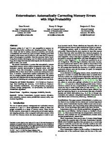
t5 0.9 average delay δ [ns]
Master clock Latche clock
t
Parity Code Split-Parity Code Duplication
0.7 0.5 0.3 0.1
∆t
1-2
Slave clock
t3 ∆
t1
t4
t6
Fig. 3.
t7
t
δ
t03
t04
– rising clock edge
Fig. 2.
t06
t07
5-8
9-16
17-32
65-128
129-256
circuit outputs [Bit]
ycomplete t01
3-4
ecomplete
– falling clock edge
Relationship between the delay and clock signals.
the combinational circuit Cir and the outputs of the predictor circuit P r. According to equation (1) the delay δ determines the minimal length ∆ of the clock cycle (or the maximal clock frequency) for which the method is applicable. Otherwise, if for a given length ∆ of the clock cycle the additional delay δ required for the computation of the error signal e satisfies the condition (1), no speed reduction is caused by the proposed method. For a given error-detecting code the additional delay δ caused by the generator Gen and the comparator Comp depends mainly only on the word length n of the output of the combinational circuit Cir and of the available technology library.
Thus the additional delay δ, which is the delay of the error signal e with respect to the completion of the output signals of the combinational circuit, is (approximately) determined by the delay caused by the generator circuit Gen and the comparator Comp. In our experiments the number of inputs of the generator circuit which is equal to the number of outputs of the combinational circuit varies from 2 to 250. Two different technology libraries, the lsi_10k library and the ihp 130 nm library were used. It can be seen that the additional delay δ grows relatively slowly with the increase of the number of input signals. For the library lsi_10k the additional delay is 10 8 times larger than for the ihp 130 nm library. For the parity codes, split-parity codes and duplication and comparison the average values for the additional delay δ with respect to the ihp library is shown in Fig. 3. The benchmark circuits are grouped with respect to the binary order of magnitude (dlog2 ne) into the sets of 1 to 2 outputs {con1}, 3 to 4 outputs {cm82a, cm85a, . . . , z4ml}, 5 to 8 outputs {clip, misex1, . . . , f51m}, 9 to 16 outputs {5xp1, cm42a, pm1}, 17 to 32 outputs {ldd, bw}, 65 to 128 outputs {x3} and 129 to 256 outputs {des}. Similar results are obtained for the lsi_10k library. For parity codes the parity bit c is determined as usual as c = y1 ⊕ y2 ⊕ . . . ⊕ yn ,
III. E XPERIMENTAL R ESULTS Experimentally the additional delay δ caused by the generator circuit Gen and the comparator Comp was determined for parity codes, split-parity codes and for duplication codes. The comparator Comp combines the corresponding pairs of check bits c(y) generated by the generator Gen and the check bits c(x) generated by the predictor P r by m XORgates. The outputs of these m XOR-gates are connected to an m-input OR-tree with a single output for the error signal e. The predictor P r may be considered as an optimized implementation of a serial connection of the combinational circuit Cir and the generator circuit Gen. For that reason the delay caused by the predictor P r is always less or equal to the delay of the (not optimized) serial connection of the combinational circuit Cir and the generator circuit Gen which is used for determining the check bits c(y). Therefore the check bits c(x) are completed not later than the check bits c(y).
Average values for the additional delay δ.
and comparison is implemented by a single XOR-gate. For the split parity codes the two check bits c1 and c2 (for an even number m of data bits) are [15] c1 = (y1 ∧ y2 ) ⊕ (y3 ∧ y4 ) ⊕ . . . ⊕ (yn−1 ∧ yn ) and c2 = (y1 ∨ y2 ) ⊕ (y3 ∨ y4 ) ⊕ . . . ⊕ (yn−1 ∨ yn ). Different split-parity codes are described in more detail, for instance, in [14]. The comparison is made by two XOR-gates, whose outputs are connected to a two-input OR-gate. Experimental results were obtained by use of a Synopsys tool from the Eurochip-project for optimization and technology mapping. The circuits were mapped onto the technology libraries lsi_10k and ihp 130 nm. The shortest delay is obtained for duplication and comparison.
285
An error which is detected by the considered code will be corrected by the proposed approach. Thus the error detection probability equals almost the error correction probability of the proposed method. In rare cases when a soft error of very short duration occurs exactly when the clock cycle is rising and which, because of its low energy cannot be detected by the error detection circuit can corrupt the memory and will not be detected by the proposed method. For benchmark circuits the error detection probabilities for parity codes and split-parity codes were determined in [14]. In [14] single stuck-at faults were injected in the circuit, pseudorandom inputs are applied and the probability that an error caused by the single stuck-at fault is detected for parity codes and split-parity codes are determined. The average error detection probability for parity codes is 80.65 % and for splitparity codes 90.62 %. The error detection probability for the duplication code is 100 %. Because the error detection probability for duplication codes is 100 % and the delay δ is minimal, the duplication code seems to be the best suited code for error correction by the proposed method.
[12] M. Goessel, V. Ocheretny, E. Sogomonyan, and D. Marienfeld, New Methods of Concurrent Checking, ser. Frontiers in Electronic Testing. Springer, 2008, vol. 42. [13] M. Goessel, E. Sogomonyan, and D. Marienfeld, “Circuit arrangement,” U.S. Patent 8 219 864, Jul. 10, 2012. [14] M. Richter and M. Goessel, “Concurrent checking with split-parity codes,” in Proc. IEEE Int. On-Line Testing Symp., Jun. 2009, pp. 159– 163. [15] M. Goessel and E. Sogomonyan, “A non-linear split error detection code,” Fundam. Inform., vol. 83, no. 1-2, pp. 109–115, 2008.
ACKNOWLEDGMENT The authors are grateful to the reviewers. Their remarks have improved the paper. R EFERENCES [1] S. Mitra, M. Zhang, N. Seifert, T. M. Mak, and K. S. Kim, “Soft error resilient system design through error correction,” in VLSI-SoC: Research Trends in VLSI and Systems on Chip, ser. IFIP International Federation for Information Processing, G. De Micheli, S. Mir, and R. Reis, Eds. Springer US, 2008, vol. 249, pp. 143–156. [2] G. Schoof, “Elektrischer Schaltkreis mit Doppel-Modul-Redundanz zur Handhabung von Single-Event-Effekten,” DE102007024983, 2008. [3] G. Schoof, M. Methfessel, and R. Kraemer, “Fault-tolerant ASIC design for high system dependability,” in Advanced Microsystems for Automotive Applications 2009, ser. VDI-Buch, G. Meyer, J. Valldorf, and W. Gessner, Eds. Springer Berlin Heidelberg, 2009, pp. 369–382. [4] V. Petrovic, M. Ilic, G. Schoof, and Z. Stamenkovic, “Design methodology for fault tolerant ASICs,” in Proc. IEEE Int. Symp. on Design and Diagnostics of Electronic Circuits Systems, Apr. 2012, pp. 8–11. [5] B. Matush, T. Mozdzen, L. Clark, and J. Knudsen, “Area-efficient temporally hardened by design flip-flop circuits,” IEEE Trans. Nucl. Sci., vol. 57, no. 6, pp. 3588 –3595, dec. 2010. [6] X. She, N. Li, and J. Tong, “Seu tolerant latch based on error detection,” IEEE Trans. Nucl. Sci., vol. 59, no. 1, pp. 211 –214, feb. 2012. [7] H. Nan and K. Choi, “High performance, low cost, and robust soft error tolerant latch designs for nanoscale cmos technology,” IEEE Trans. Circuits Syst. I: Reg. Pap., vol. 59, no. 7, pp. 1445 –1457, july 2012. [8] D. Ernst, S. Das, S. Lee, D. Blaauw, T. Austin, T. Mudge, N. S. Kim, and K. Flautner, “Razor: circuit-level correction of timing errors for low-power operation,” IEEE Micro, vol. 24, no. 6, pp. 10–20, Nov.-Dec. 2004. [9] S. Das, C. Tokunaga, S. Pant, W.-H. Ma, S. Kalaiselvan, K. Lai, D. Bull, and D. Blaauw, “RazorII: In situ error detection and correction for PVT and SER tolerance,” IEEE J. Solid-State Circuits, vol. 44, no. 1, pp. 32–48, Jan. 2009. [10] S. Mitra, M. Zhang, T. M. Mak, N. Seifert, V. Zia, and K. S. Kim, “Logic soft errors: a major barrier to robust platform design,” in Proc. IEEE Int. Test Conf., Nov. 2005, pp. 687–696. [11] M. Nicolaidis, Soft Errors in Modern Electronic Systems, ser. Frontiers in Electronic Testing. Springer, 2011, vol. 41, ch. Circuit-Level SoftError Mitigation, pp. 203–252.
286