A New Method for Recognizing Objects in Photos Taken by Smart Phones Jaegeol Yim, Jaehun Joo, Silvana Trimi
A New Method for Recognizing Objects in Photos Taken by Smart Phones 1
Jaegeol Yim, 2Jaehun Joo, 3Silvana Trimi Computer Engineering Department Dongguk University, Gyeongju, Gyeongbuk, 780-714 Republic of Korea,
[email protected] *2,Corresponding Author Information Management Department Dongguk University, Gyeongju, Gyeongbuk, 780-714 Republic of Korea,
[email protected] 3 Management Department, University of Nebraska – Lincoln, Lincoln, NE, 68588, USA,
[email protected]
1, First Author
Abstract With the advances in computing power and storage capacity of smart phones, cloud computing and wireless networks, new apps and services are being developed and offered to the users of smart phones. One of these new services is the mobile augmented reality system (MARS). MARS integrates virtual information into the physical environment where a smart phone is located, allowing smart phone users to receive virtual information as if it is part of their physical surroundings. Several studies have suggested techniques/methods to match the best relevant information with the physical surrounding/object. Most of them identify the objects on the photo based on image comparison of the photo taken by a smart phone with images stored in a database. This method however is slow, as it takes time to do the image comparison. In this study we propose a new method, which can identify objects in a smart phone photo much faster and with a higher degree of accuracy, by using the phone’s sensor data and electronic maps.
Keywords: Augmented Reality, Object Recognition, Context Aware, Virtual Reality, Smart Phones
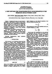
1. Introduction With the advent of rapid advances in information and communication technology (ICT), the computing power and the storage capacity of smart phones have accelerated. The recent developments in the speed and bandwidth of networks, and the increased usage of cloud computing and storage, have elevated competition in offering many new applications and useful services on smart phones. The context-aware service [4, 5] and mobile augmented reality service (MARS) [7, 13] are two of the most recent and popular services. The context-aware service provides the user with the most appropriate service, considering the user’s surrounding physical environment, location, personal interests, and so on. MARS has added graphics, texts, and sound to a photo image. For example, in MARS shown in Fig. 1, an arrow labeled “To CSE 591” directs the user to reach CSE 591 (Computer Science & Engineering Building Room 591), while the two windows inform the user that “CSE 502 is the grad office” and “CSE 503 is a conference room” [6]. The arrow and windows are not part of the picture. They are augmented to the picture to deliver valuable information to the user. Such augmented reality is derived if the system identifies the objects in the picture, determines the relevant content, and displays the information in the screen to the user. Thus, identifying an object in the picture taken by the phone camera is important for both context-aware service and mobile augmented reality. Numerous studies have developed several techniques to identify objects and are used in several applications. For example, in an educational mobile application for children, when a child takes a picture of a marked object in a museum or a park, the application identifies the item, retrieves the information related to the item from the Internet and displays it [9]. In a museum guide system, when a visitor takes a picture of an exhibited item, the item is identified and related multimedia content is displayed [2]. Currently, all the existing object recognition techniques are based on image comparison, comparing the photo with the images stored in the database [3, 15]. This image comparison method of comparing pixel values, pixel by pixel, is time consuming and error-prone. For example, if image B is one pixel
Journal of Convergence Information Technology(JCIT) Volume8, Number13, August 2013
289
A New Method for Recognizing Objects in Photos Taken by Smart Phones Jaegeol Yim, Jaehun Joo, Silvana Trimi
ft off image A A, then, even tthough the objject in image A is identicall to the objectt in image B, this shift imagge comparisonn method will erroneously conclude c that tthe two imagees are not the same. s
F Figure 1. An E Example of M Mobile Augm mented Realityy (Source: [6]) Inn this paper, we propose a method whiich is radicallly faster and more accuratee than any off the exissting photo reecognition methods. This m method does nnot use the photo image comparison c att all. Rathher, it leveragges on the higgh accuracy of the current smart phoness’ sensors andd electronic m maps. Elecctronic maps oof interesting domains are widely availaable, includingg most large sstructures. Heence, com mpared to otheer apps, such as marker-baased applicatioons, our methhod does not rrequire an offfline phasse. The processsing time to rrecognize an object o is mostlly the time it ttakes to find thhe elements off the mapp (around the location of thhe smart phonee) that interseect with the linne-of-sight (off the camera w with the object). The eexecution timee of this proceess is proportional to the nnumber of elem ments in the m map, whicch are no morre than a few hhundreds, thuss making the pproposed methhod radically faster than anny of the existing e photoo recognition m methods. A After this intrroductory secttion, we pressent the literaature review rrelated to ourr study. Our new apprroach regardinng an object rrecognition meethod is propoosed and expeeriment resultss of our approoach are introduced. i Fiinally, we disccuss implicatioons of our studdy and concludde.
2. L Literature R Review T paper prooposes a new method This m of reccognizing objeects when a sm mart phone pooints at them. T This topic is importantt and, as such,, it has been tthe focus of m many studies. M Most current m methodologiess for objeect recognitionn can be groupped as follows: 1) IImage compaarison metho d: This methhod comparees the photo with the imaages stored iin a daatabase. Extraacting the im mage features,, an ID is creeated for a giiven image aand is stored in a daatabase [1]. T The scope off the imagess to search aand to compaare with a p hoto taken by b a caamera is narrrowed down by analyzingg the phone’ss sensor dataa [3, 15]. Onne of the studdies evven develope d a new patttern discove ry algorithm m for noisy im mages [8]. O Once the cloosest im mage from the server is iddentified, thee server sendds the scene ddescriptions in both text and auudio to the phhone. Anotherr mobile appllication was ddeveloped forr building reccognition [19 ]. If a uuser takes a ppicture of a bbuilding and sends it to a remote serv er along withh its GPS datta at the moment off taking the picture, thenn the server matches the photo with the stored G GPStaggged images,, using a com mbination of the scale salliency algoritthm for featuure matching and the earth move r’s distance m measure for scene s matchinng. 2) F Feature basedd method: A feature cann be anythingg that is use d to describee an object. For exxample, if thee object is a person, featuures can be: the color off face, eye orr hair, weighht or heeight, DNA ssequence, etcc. A feature for image coomparison caan be the sum m of horizonntal, veertical, and diiagonal pixel values of thee picture. By using the rigght feature, annd by comparring the feature vaalues of two persons, fo r example, w we can deteermine if theey are identiical. Hoowever, featuure based imaage comparisson is also tim me consuminng. For exampple, suppose that wee conclude tw wo images aree match whenn 4 feature pooints match. S Suppose furthher that a cam mera
290
A New Method for Recognizing Objects in Photos Taken by Smart Phones Jaegeol Yim, Jaehun Joo, Silvana Trimi
image has 10 feature points and the map image has 32 feature points. Then there will be 4 billion different possible 4-point correspondences to check and compare [6]. 3) Model based methods [14, 17]: Before starting the recognition process, a model based method must build and store models of many objects of interest. A model is human constructed representation of a real world object. For example, for building recognition, we should have models of buildings. A 2-D model of a building, for example, might be a rectangle. During the recognition process, a segmentation algorithm is applied, where (in the most primitive segmentation algorithm) the pixel values of two adjacent pixels are compared and grouped together, if they are not so different; otherwise they are separated. As the result of the segmentation, the boundaries of groups are obtained. If a boundary is similar to the model of an object, the recognition process determines that the boundary is the object. For example, if a boundary is similar to a stored rectangle (model), the method concludes that that is the building. Thus, a model based building recognition method must develop at least one model for each of the buildings in the domain of practice, which is time consuming and, along with the processing time of comparison, makes this method slow. 4) Landmark based methods [12, 16]: This method creates a database of landmarks before running the recognition process. Landmarks can be different objects, such as a big statue, a huge sculpture, and a large building. A landmark can also be a part of a building. If a landmark is in the photo, then we can conclude that we are around there. For example, the administration building might have a clock (landmark) at the top center of the building. The landmark based method concludes that the building in the photo is the administration building if it finds a clock in the photo. 5) Markers method: This method consists of two phases: the offline phase and the online phase [10, 18]. During the offline phase, markers (Quick Response (QR) code tags) are attached on each of the interested objects in the application domain, and the pair values for markerID/object-ID are recorded in a database. A picture of a marker, taken during the on-line phase, is compared (by the application) with every marker pair value in the database. The item’s information is determined and given back to the user, by retrieving the pair in the database that matches the image taken by the camera. The user then, by taking a picture of an item/marker (QR) in a store, for instance, can see where else and for how much that item is being sold. For example, in Table 1, if the picture taken corresponds to the marker (0 1 0 0 0 0 1 0 0 0) then object5 will be returned. Table 1. Database Example (built by the app’s developer during the off-line phase) Marker 0100001100 0000001100 0101001100 1100001100 0100001000 ... 0100011100
ObjectID object1 object2 object3 object4 object5 ... objectn
Even though some researchers may claim that the marker-based application is fast and the most efficient image analysis method, the offline phase takes time and therefore it is a drawback. In addition, this method cannot recognize the object unless the camera points directly at it and takes a very clear picture of QR code (which is 2D-kind barcode). Some other studies have tried to overcome the limitations in the processing speed and accuracy of recognizing objects. Thus, those that use the indoor positioning infer the user’s context through a decision tree method. This method uses data obtained through the Wireless Local Area Network,(WLAN) and a Bayesian network inference scheme [11, 20]. An augmented reality smart phone application was developed by using the indoor position method to estimate the position and the pose of the camera [13]. As we can see from these discussions and examples, most of the existing methods for picture recognition rely on image comparison techniques. Even though some of them use GPS data to narrow down the number of images to be compared with the photo taken, all the current image comparison
291
A New Method for Recognizing Objects in Photos Taken by Smart Phones Jaegeol Yim, Jaehun Joo, Silvana Trimi
techniques rely on the photo recognition at the final stage, and therefore are very time-consuming. In this study, we propose a much faster method of recognizing objects on photos taken by a smart phone, based on the highly accurate sensors of today’s smart phones and on electronic maps.
3. The Proposed Object Recognition Method Today’s smart phones are equipped with GPS, which measures the phone’s location with an error as little as 10 meters, and with compass, which measures the phone’s orientation with an error of less than two degrees. Our proposed method uses the phone’s location and orientation to first calculate the lineof-sight of the camera with the object. The line-of-sight of the camera indicates the line connecting the camera and the object taken by the camera. The user’s location is provided by the phone’s GPS. The orientation information is drawn from azimuth, pitch and roll values, all provided by the compass of the phone. The required time for obtaining the sensor data and calculating the line-of-sight is so short that it can be ignored to estimate in our method. Next, the proposed method finds the element of the map that intersects with the line-of-sight. An electronic map consists of lines, polygons, arcs, circles and so on. The method identifies the object in the photo by investigating those intersecting elements of the line-of-sight with those in the map. The intersecting element whose distance from the camera is closest to (or the same as) the focus distance of the camera is the one that represents the object in the photo. Methods for finding the focus distance of the camera are available, such as the getFocusDistances() for Android phones.
3.1 Accuracy of Sensors The proposed method of recognizing the object in a picture taken by a smart phone camera stems from the fact that nowadays sensors on a smart phone are very accurate. Before running our proposed algorithm, we first tested the accuracy of the sensors on a smart phone by performing the following: (1) location test – by using LocationManager, and (2) compass test –by using SensorManager. First, we specifically chose two points A and B, with the following coordinates on the Google Map: A: 129.196990 (longitude), 35.861779 (latitude) B: 129.196 472 (longitude), 35.861650 (latitude). (1) To measure the accuracy of the location measurement, we ran the LocationManager on a Galaxy S2 smart phone several hundred times at the two chosen points, A and B. First, we calculated the averages of the returned values, for both A and B. Then, we calculated the distance (error) of the averages from point A and B (Table 2). Table 2. A Summary of Results of LocationManager Tests on a Galaxy S2
Google Coordinate Measurement (Average) Error (degree) Error (meter)
Location A longitude latitude 129.196990 35.861779 129.1968912 35.8619749
Location B longitude latitude 129.196472 35.861650 129.1964195 35.8616350
0.00009880 7.528311
0.0000525 3.843647
-0.0001959 11.493384
0.0000150 10.243619
It is known that the distance from longitude 129 degree to 130 degree, at latitude 36 degree, is about 91.29 Kilometers. The distance from latitude 35 degree to 36 degree is about 110.941 Kilometers. Thus, the average error of the measurements obtained at location A (B) is about 13.73948193 meters (10.94099438 m). We did other tests from other locations, and based on the overall measurements obtained, we concluded that the average error of LocationManager on Galaxy S2 was approximately 11.52493934 meters. (2) To measure the accuracy of the compass on the Galaxy S smart phone, we performed several experiments where we measured azimuth of Galaxy S when it was aimed at a point C(B) from point A (Fig. 2). Point A is the spot where we stood and ran the SensorManager many times. C and B were
292
A New Method for Recognizing Objects in Photos Taken by Smart Phones Jaegeol Yim, Jaehun Joo, Silvana Trimi
muth of the linee-of-sight, deffined thee points to whhich we faced to read the azzimuth at pointt A. The azim byy the start poinnt A and the ennd point C (B)) (AtoC; AtoB B), was calculaated by the folllowing equation: Azim muth 90 Attan * (Slope off the line) (1) W Where Atan stannds for arc tanngent, and “the slope of a linne,” defined by b two points, A(the start pooint) annd C (B) (the end e point), was calculated byy the followinng equations: S Slope (AtoC) latitude of A - latitude of C *110941 / llongitude of C - longitude off A * 91290 Sloppe (AtoB) laatitude of A - llatitude of B *110941/ longgitude of B - loongitude of A * 91290
F Figure 2. Com mpass Accuraccy Test at Poinnt A T results of the accuracy tests The t are show wn in Table 3. Using Googlee map coordinnates and Equaation 1, thhe azimuth wee obtained forr AtoC was 222.95307631. H However, the m magnetic northh that a (phonne’s) com mpass points too is not the saame as the (geeographic) maap north. Thuss, we had to aadjust the valuue of the calculated azzimuth for this difference. Using a milittary compass,, we found thhat the differeence betw ween the magnnetic north annd the grid (m map) north waas about 7.5 ddegree. Thereffore, the correected azim muth of our Gaalaxy S for AttoC would be 30.45307631 and for AtoB B would be 2988.7303745, whhich meaans that the aveerage error off measured azim muths is abouut 14.6 degreess (Table 3). Table 33. Azimuth Teest Results From P Point A Measured azim muth (average)) Corrected d azimuth Error
Pooint B 284.147886 298.7303745 14.5824885
Point C 15.806921 30.453076311 14.646155311
Table 4.. The Pitch Acccuracy Test Laatitude Lon ngitude Altitud de (meter) Heigh ht (meter) Disstance
Aveerage of Measu urements Measured d Pitch (Eq. 2) Calcculated Pitch h (Eq. 3) E Error
Point A 35.86162 129.196271 40 1.67 0
P Point B 35.861776 129.195783 41 9.71 47.79314721 = square root of ((35.86162-35.861776)2 +(129.1962711-129.195783)22 +((40+1.67)-((41+9.71))2 -100.3
Poiint C 35.8620663 129.1964499 45 15.51 53.372666842
10.3 10.71086981
20.6 19.442500491
10.3 - 10.71086981 = - 0.410869881
20.6 19.442500491 = 1.157449509
-110.6
-
293
A New Method for Recognizing Objects in Photos Taken by Smart Phones Jaegeol Yim, Jaehun Joo, Silvana Trimi
When we collected the azimuth values, we also collected pitch values (Table 4). The pitch value is the degree/angle of the elevation of the line-of-sight determined by the camera and the object. Android provides classes and methods (something similar to library functions) that return sensor values, and SensorOrientation is the method that returns azimuth, pitch and roll. SensorOrientation puts its return values in Values [ ] (variable name), an array of real numbers of size 3 cells. When we hold a Galaxy S in the portrait orientation, Android’s SENSOR_ORIENTATION returns a pitch value at values[1] (azimuth at values[0] and roll at values[2]). When the screen of a Galaxy S faces the sky (laid parallel to the earth), the returned value for the pitch (variable values [1]) is 0. As the top edge of the phone is pulled toward the holder, when the phone is in straight portrait orientation, the value of the pitch (variable values[1]) decreases to -90. Thus, we can obtain the angle of elevation (in degrees) from variable values[1] read from the Sensor, with the following equation: Measured angle of elevation -90 - values[1] (2) The heights of points are the distances between the ground and the phone. In our tests, they were specifically1.67 for point A, 9.71 for point B, and 15.51 for point C. Distance is the distance between A to A, A to B and A to C. The height and distances were used to calculate the estimated pitches, with the following formula: Sin ( Angle of elevation) dist ance / height (3) Thus, the measurement errors of the pitch values are calculated as the difference between the average of measured pitches (Equation 2) and the calculated pitches (Equation 3). As shown in the Table 4, Values [1] measured at point A were: for the phone aiming at point B:(-100.3) and aiming at point C:(-110.6). Using Equation 2, measured pitches were about 10.3 for B and 20.6 for C. Using Equation 3, calculated pitches were about 10.71086981 for A, and 19.44250491 for B. Therefore, the pitch measurement error was 0.41086981 degree for point B and 1.15749509 degree for point C (Table 4).
3.2 The Proposed Algorithm This paper proposes a new method of recognizing objects in photos taken by a smart phone camera. This is new because it uses electronic maps for the first time. Thus far, the accessories attached to a mobile phone have not been accurate enough to locate the phone on a map, to determine the camera orientation and to measure the focus distance of the camera. Therefore, all the existing picture recognition systems rely on image processing techniques. Many of them do make use of GPS and compass data to narrow down the scope of the images in a database to be compared with the phone photo. However, they all rely on image processing techniques at the final stage of photo recognition, which is time consuming, and therefore slow. Today’s smart phones’ sensors are highly accurate. The measurement error of a GPS (compass) on a recently released smart phone is about 10 meters (less than 15 degrees). Thus, by taking advantage of the highly accurate sensors of current smart phones, we propose a new method for object recognition, that completely avoids time-consuming image processing and instead it employs electronic maps. Since we used an Android phone to design and test this method, the below explanations of the steps in the proposed method do incorporate specifics related to this types of phones. The object recognition method proposed is done as follows: 1) Obtain an electronic map of the physical area that relates to the application system that uses the map. For example, when considering an application for campus guide, we need a drawing (in AutoCAD) of the campus and its buildings. These drawings, especially for the big buildings, usually already exist. However, the level of the details of the drawing is closely related to the purpose of the application. If we want a campus guide only at the building level(being the lowest level), the object recognition process should be able to identify the name of the building in a photo. An illustration of an electronic map for this application is shown in Fig. 3. The electronic map consists of “edges,” representing the outlines of buildings (Natural Science Building, Gymnasium Building, Student Hall, and so on). Edges are represented by a pair of points, start and end, and each point is represented by a pair of real numbers (longitude, latitude).
294
A New Method for Recognizing Objects in Photos Taken by Smart Phones Jaegeol Yim, Jaehun Joo, Silvana Trimi
Natural Science 129.198050, 35.862546 ... 129.198050, 35.862546 Gymnasium 129.196986, 35.862514 ... 129.196986, 35.862514 Students Hall 129.195878, 35.862025 ... 129.195878, 35.862025 ... Figure. 3 An Illustrative Electronic Map of a University Campus 2) With the phone’s sensor, we determine the location of the smart phone. Most of the smart phones are equipped with a GPS receiver, WiFi device, 3G or 4G communication device. In Android, the “LocationManager” class provides a method that identifies the location of the smart phone, by using data from these devices. 3) We collect the orientation data, namely azimuth, pitch, and roll values. In Android, “SensorManager” class provides a method that measures these values. 4) Using the “Camera” class, we determine the focus distance of the camera. In Android, the “Parameters” class, nested in the “Camera” class, provides the getFocusDistance method that calculates and returns the focus distance. 5) Finally, we execute our proposed “Object Recognition Algorithm” (explained in the next section) to identify the object on the camera.
3.3 Proposed Object Recognition Algorithm The proposed algorithm steps are as follows (Fig. 4): Find the line-of-sight of the camera with the object, by using the location and orientation data. Find the element (edge) of the electronic map intersecting with the line-of-sight. Find the distance between the phone and the element (edge). If the distance is close to the focus distance, then we conclude that the building (the point of interest) whose outline contains the element (edge) is the object in the photo. If there is no such element, then the algorithm concludes that the object on the photo is not something that is represented/found on the electronic map and returns Nil. objectRecognitionAlgorithm (fd, location, azimuth, pitch, eMap) // fd: focus distance ; // location: (longitude, latitude, altitude) Step 1: With location x, y , z , and azimuth, calculate the following formula whose slope is obtained from the azimuth value. ….. (Eq. 1) ax b y Step 2: Find S = { s | s is an edge in eMap which intersects Eq. 1}. Step 3: If S is an empty set then return NIL Step 4: Find the edge “e” in S which is closest to the location. Delete “e” from S. Let the building whose outline contains “e” to be a “candidate building,” and the intersect point of “e” and Eq. 1 be (x’, y’). Step 5: Let the distance between (x, y) and (x’, y’) be d. Step 6: If “z+d*tan(pitch)” is between the bottom and top of the “candidate building” then go to Step 7. Else, go to Step 3. Step 7: Let the distance between (x, y, z) and (x’, y’, z+d*tan(pitch)) be dist. If (|dist – fd| < threshold), where threshold is a small number representing the error of
295
A New Method for Recognizing Objects in Photos Taken by Smart Phones Jaegeol Yim, Jaehun Joo, Silvana Trimi
getF FocusDistanceethen return “ccandidate buildding” E return NIL Else L. Figuree 4. The propoosed “Object Recognition R A Algorithm”
F Figure 5. The Object Recoggnition Algoritthm
F Figure 6. Testt of the Reliabiility of the Proogram in a Virrtual Environm ment B Because we teested the propposed algorithhm using an A Android SDK K, version 2.22, which does not suppport getFocusD Distance(), thee program we developed andd tested was slightly differeent from the abbove propposed algorithhm: if “z+d*tann(pitch)” is beetween the botttom and top oof the “candiddate building,”” the proggram, instead oof jumping to Step 7, returnns the “candidaate building” and a terminatess at Step 6.
3.4 Implementaation of the “Object “ Reccognition Alggorithm” M Method (1) IIn onCreate, thhe program innstantiates:LoccationManagerr to get the loccation data, annd SensorManager to get the orientation data. (A) LocationM Manager is insttantiated with the following statement: ((LocationMannager)getSysteemService(Conntext.LOCATIION_SERVIC CE);
296
A New Method for Recognizing Objects in Photos Taken by Smart Phones Jaegeol Yim, Jaehun Joo, Silvana Trimi
U Using the getB BestProvider method of LoocationManagger, we find tthe name of tthe most accuurate locaation provider of the smart phone on whhich the prograam is runningg. In onResum me, we invokee the requuestLocationU Updates method of LocationnManager withh the best provvider, and the LocationListeener. The LocationListeener returns thhe set {longituude, latitude, aaltitude}. (B) SensorMaanager usage is similar to the LocationnManager’s, thherefore we oomit the detaailed expllanation. In ouur program, iff SensorManagger.SENSOR__ORIENTATIION is changeed, then we obbtain new w azimuth and pitch values. (2) The T IdentifyO Object, shown in Fig. 5, is thhe workhorse oof this program m. Making usee of MathMethhod, thiis activity findds: the closest c edge thhat intersects w with the line off sight of objeect-camera deterrmines the buiilding whose ooutline containns the edge returrns the buildinng name, if thee line of sight hhits the buildinng. T This proposedd method of rrecognizing thhe object on a picture takenn by a smart phone camerra is highhly accurate ass the sensors oon the smart phhone today haave become quuite accurate.
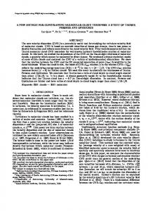
4. E Experimentt Results Inn order to verrify the reliabbility of the im mplemented A Android prograam, we tested the program in a virtuual situation, sshown in Fig. 6. In the figurre, Top, Bottom m, Right and Left L representt buildings andd the cam mera is located at the dot at thhe center. Thee coordinates of o the start point are (129.1994977, 35.8622395) and the coordinattes of others aare all shown iin the figure. If the azimuthh value is betw ween 60 and 130, thenn the result shoould be Right, and so on. W We ran the appp and fed an arbitrary a numbber as the azim muth valuue and checkedd if the result is correct. Froom this test, we w found that the implemennted app is corrrect for aall the azimuthh values, thus proving that tthe program iss reliable. F Figure 7 proviides a snapshoot of the smarrt phone, runnning the prograam. The text bbox indicates that the edge e intersectiing the line-off-sight is found to be the “T Top”.
Figure 7. 7 Snapshot off the Smart Phoone Running tthe Program
F Figure 8. A Sccreenshot of thhe Galaxy S2 Running the P Proposed Proggram A After confirmiing the reliabbility of the proposed p proggram with viirtual scenarioos, we perform med expeeriments to teest our objectt recognition program, on a Galaxy S22 phone, by ttaking pictures of
297
A New Method for Recognizing Objects in Photos Taken by Smart Phones Jaegeol Yim, Jaehun Joo, Silvana Trimi
buildings on a real university campus. The results, again, confirmed the accuracy of our program to correctly identify objects in the picture. The screenshot of Galaxy S2 running the proposed program, shown in Fig. 8, shows the “Result: StudentsHall,” which means that the object in the picture was correctly identified as “Students Hall.” The proposed algorithm was tested by taking pictures and identifying buildings of many shapes and sizes, and at several distances. Running the proposed program, we found that it is 100% accurate when the distance between the building and smart phone was less than 50 m; and about 85% correct when the distance is 90m or more. These results definitely prove the reliability of our proposed algorithm for building identification. However, most of the campus buildings are large with widths greater than 70m and heights taller than 20m. Therefore, to verify the reliability of the proposed methods for identifying any object, in addition to buildings, we performed experiments with all other types of objects in different shapes and sizes. Thus, we took pictures from different distances, of an elephant statue with width of 5m and height about 7m. The results showed that the average of successfully identifying the statue with our proposed program was: 100% when the distance from the camera to the object was less than 7m; 47% when the distance from the camera to the object was10m.Considering that in the real world pictures of objects are rarely taken in over 10m distance, we can conclude that our proposed object recognition method is quite reliable.
5. Discussion and Conclusion This paper proposed a new method to identify objects in pictures taken by smart phones’ camera. The current object recognition application methods are time consuming as they are based on camera image comparison with a large number of pictures stored in database. Our proposed method, using the orientation, location, and focus distance obtained via smart phones’ highly accurate sensors and devices (compass, GPS, and camera) and electronic maps, eliminates the comparison process, and therefore radically reduces the time to identify an object in the camera phone picture. We used an Android Galaxy S2 phone to test the accuracy of the proposed algorithm because they are equipped with highly accurate sensors. Even though we use Android’s “GetFocusDistance,” in our object recognition algorithm, the function does not return any meaningful values when it is executed on Galaxy S or S2. Thus, the function was not used in the program we executed in our experiments. The requirement for highly accurate sensors to run the proposed program currently limits the usage of this method across mobile phones. In the very near future, Software Development Kit (SDK) and Android Development Tools (ADT) will be improved and smart phones will be equipped with much more accurate sensors. Then, our proposed algorithm will be even more accurate and the algorithm will be very useful and valuable across all smart phones in the near future. There are positive implications of the proposed method for the existing businesses and opportunities for new ventures. It can open up many opportunities for new products and services. The automatic and fast recognition of an object enables businesses to provide smart phone users with more personalized and smart services. For example, since taking a picture of an object means that the person is interested in the object, relevant content or information on the pictured object can be automatically provided to the user. Travelers can get smart services, personalized content, or augmented reality for real-world objects, by simply taking a picture. Twitter already offers a service which adds a location to a photo or video. However, users must specify where the photo or video was taken. By integrating the method proposed in this research to the Twitpic service of Twitter, for example, we can remove the need for the user’s manual input and will make the service smarter.
ACKNOWLEDGEMENTS This research was supported by Basic Science Research Program through the National Research Foundation of Korea(NRF) funded by the Ministry of Education (NRF-2011-0006942).
References [1] Abe, T., Takada, T., Kawamura, H., Yasuno, T., & Sonehara, N., “Image-Identification Methods for Camera-Equipped Mobile Phones”, In International Conference on Mobile Data Management, pp. 372-376, 2007.
298
A New Method for Recognizing Objects in Photos Taken by Smart Phones Jaegeol Yim, Jaehun Joo, Silvana Trimi
[2] Bruns, E., Brombach, B., & Bimber, O., “Mobile Phone-Enabled Museum Guidance with Adaptive Classification”, IEEE Computer Graphics and Applications, vol. 28. No. 4, pp. 98-102, 2008. [3] Cipolla, R., Robertson, D., & Tordoff, B., “Image based Localization. In Int. Conf. on Virtual Systems and Multimedia”, VSMM, pp. 22-29, 2004. [4] Dao, T., Jeong, S., & Ahn, H., “A novel recommendation model of location-based advertising: Context-Aware Collaborative Filtering using GA approach”, Expert Systems with Applications, vol. 39. No. 3, pp. 3731-3739, 2012. [5] Espada, J., Crespo, R., Martínez, O., G-Bustelo, B., & Lovelle, J., “Extensible architecture for context-aware mobile web applications”, Expert Systems with Applications, vol. 39. No. 10, pp. 9686-9694, 2012. [6] Hile, H., & Borriello, G., “Positioning and Orientation in Indoor Environments Using Camera Phones”, IEEE Computer Graphics and Applications, vol. 28, no. 4, pp. 32-39, 2008. [7] Lee, J., Huang, C., Huang, T., Hsieh, H., & Lee, S., “Medical augment reality using a markerless registration framework”, Expert Systems with Applications, vol. 39, no.5, pp. 5286-5294, 2012. [8] Lim, J., Li, Y., You, Y., & Chevallet, J., “Scene Recognition with Camera Phones for Tourist Information Access”, IEEE International Conference on Multimedia and Expo, pp. 100-103, 2007. [9] Mitchell, K., & Race, N., “uLearn: Facilitating Ubiquitous Learning Through Camera Equipped Mobile Phones”, In IEEE International Workshop on Wireless and Mobile Technologies in Education, 2005. [10] Mohring, M., Lessig C., & Bimber, O., “Video See Through Consumer Cell-Phones”, In International Symposium on Mixed and Augmented Reality (ISMAR 2004), pp. 252-253, 2004. [11] Noh, H., Lee, J., Oh S., Hwang, K., & Cho S., “Exploiting Indoor Location and Mobile Information for Context-Awareness Service”, Information Processing & Management, vol. 48, no. 1, pp. 1-12, 2012. [12] Oe, M., Sato, T., & Yokoya, N., “Estimating Camera Position and Posture by Using Feature Landmark Database”, In Scandinavian Conference on Image Analysis (SCIA 2005), pp. 171-181, 2005. [13] Paucher, R. & Turk, M., “Location-Based Augmented Reality on Mobile Phones”, In IEEE Computer Society Conference on Computer Vision and Pattern Recognition Workshops (CVPRW 2010), pp. 9-16, 2010. [14]Rosten, E., & Drummond, T., “Fusing Points and Lines for High Performance Tracking”, In International Conference on Computer Vision (ICCV 2005), pp. 1508-1515, 2005. [15] Sato, J., Takahashi, T., Ide, I., & Murase, H., “Change Detection in Streetscapes from GPS Coordinated Omni-Directional Image Sequences”, In International Conference on Pattern Recognition (ICPR 2006), pp. 935-938, 2006. [16] Skrypnyk, I., & Lowe, D., “Scene Modelling, Recognition and Tracking with Invariant Image Features”, In International Symposium on Mixed and Augmented Reality (ISMAR 2004), pp. 110119, 2004. [17] Vacchetti, L., Lepetit, V., & Fua, P., “Combining Edge and Texture Information for Real-Time Accurate 3D Camera Tracking”, In International Symposium on Mixed and Augmented Reality (ISMAR 2004), pp. 48-57, 2004. [18] Wagner, D., & Schmalstieg, D., “First Steps Towards Handheld Augmented Reality”, In International Symposium on Wearable Computers (ISWC 2003), pp. 21-23, 2003. [19] Yeo, C., Chia, L., Cham, T., & Rajon, D., “Click4BuildingID@NTU: Click for Building Identification with GPS-enabled Camera Cell Phone”, In IEEE International Conference on Multimedia and Expo, pp. 1059-1062, 2007. [20] Yim, J., “Introducing a Decision Tree-based Indoor Positioning Technique”, Expert Systems with Applications, vol. 34, no. 2, pp. 1296-1302, 2008.
299