IEEE TRANSACTIONS ON SYSTEMS, MAN, AND CYBERNETICS—PART B: CYBERNETICS, VOL. 34, NO. 1, FEBRUARY 2004
419
A New Mobile Robot Control Approach via Fusion of Control Signals Eduardo Freire, Teodiano Bastos-Filho, Member, IEEE, Mário Sarcinelli-Filho, Senior Member, IEEE, and Ricardo Carelli, Senior Member, IEEE
Abstract—This paper proposes an alternative approach to address the problem of coordinating behaviors in mobile robot navigation: fusion of control signals. Such approach is based on a set of two decentralized information filters, which accomplish the data fusion involved. Besides these two fusion engines, control architectures designed according to this approach also embed a set of different controllers that generate reference signals for the robot linear and angular speeds. Such signals are delivered to the two decentralized information filters, which estimate suitable overall reference signals for the robot linear and angular speeds, respectively. Thus, the background for designing such control architectures is provided by the nonlinear systems theory, which makes this approach different from any other yet proposed. This background also allows checking control architectures designed according to the proposed approach for stability. Such analysis is carried out in the paper, and shows that the robot always reaches its final destination, in spite of either obstacles along its path or the environment layout. As an example, a control architecture is designed to guide a mobile robot in an experiment, whose results allows checking the good performance of the control architecture and validating the design approach proposed as well. Index Terms—Control system stability, decentralized information filter, fusion of control signals, mobile robots, motion control.
I. INTRODUCTION
T
HE indoor navigation of a mobile robot in dynamic environments is addressed in this paper, regarding that the position/dimension of any possible obstacle and the environment layout itself are a priori unknown. Two basic assumptions about the environment, however, are made: it has a plain ground and allows at least one free path connecting a starting point to a reachable destination point. Reactive, or behavior-based, control architectures are supposed to be used to control the robot navigation, so that a group of distinct behaviors is available at each time instant. Then, an Action Selection Problem (ASP), also called a Behavior Coordination Problem [14], is character-
Manuscript received April 16, 2002; revised November 5, 2002. This work was supported in part by grants from CAPES Foundation, FAP-SE and UNIT, from Brazil, and ANPCyT, CONICET, UNSJ and SETCIP, from Argentina. It is also part of an international partnership between Federal University of Espírito Santo, Vitória, ES, Brazil and National University of San Juan, San Juan, Argentina. This paper was recommended by Associate Editor C. T. Lin. E. Freire is with the Department of Electrical Engineering, Federal University of Sergipe, Aracaju, SE, 49032-490, Brazil (e-mail:
[email protected]). T. Bastos-Filho and M. Sarcinelli-Filho are with the Department of Electrical Engineering, Federal University of Espírito Santo, Vitória, ES, 29060-900, Brazil (e-mail:
[email protected];
[email protected]). R. Carelli is with the Institute of Automatics, National University of San Juan, San Juan, 5400, Argentina (e-mail:
[email protected]). Digital Object Identifier 10.1109/TSMCB.2003.817034
ized, which should be solved accordingly, through the design of a suitable control architecture, also known in the literature as an Action Selection Mechanism (ASM). The ASMs currently available in the literature can be classified as arbitration schemes or command fusion schemes. Arbitration schemes perform behavior selection, because they select a single behavior to deliver the control signals corresponding to the linear and angular speeds to the robot actuators. These ASMs can be classified as Priority Based mechanisms, Winnertakes-all mechanisms or State Based mechanisms, depending on how they perform the behavior selection. Some examples of arbitration schemes are the Brooks’ Subsumption Architecture [16], Discrete Event Systems, and Activation Networks [14]. In a command fusion scheme, on the other hand, a set of behaviors contributes to generate the overall linear and angular speed control signals. There are several ways to implement command fusion schemes. Some examples are Voting (e. g. DAMN architecture [3], [4], [11], [12]), Superposition (e.g., AuRA architecture [18], [19]), Multiple Objective Optimization (e.g., Multiple Objective Decision-Making Control [14]), and Fuzzy Logic (e.g., Multivaluated Logic Approach [2]). Another example of an ASM that implements command fusion is the dynamic approach to behavior-based robotics [5], [9]. In the context of behavior coordination, the sensorial data the control system onboard a mobile robot should manage come from a diversity of sensors, like ultrasonic transducers, infrared receptors, laser range finders, and video cameras, many times simultaneously. When this is the case, it is not feasible to use sensor fusion to pack all the sensorial data into a single useful information, because of the very diverse nature of the sensors used. For managing this diversity of sensorial information, this paper proposes a new approach to design a suitable ASM: the design of a group of distinct controllers to deal with the information originated in a specific sensor, or group of similar sensors, and the fusion of the signals in the output of these controllers. The outputs of such controllers are signals that correspond to linear and angular speeds, so that their fusion can always be performed. The proposed scheme uses the decentralized information filter (DIF) [1] to make such fusion [6]–[8]. In such context, a behavior corresponds to a single controller or even to a group of similar controllers (different controllers receiving information from different sensors, with the goal of increasing the confidence of the control system). Then, the task of behavior coordination, now translated to the task of coordinating the distinct controllers, is performed by two DIFs, which estimate a suitable overall control signal for the robot linear speed and
1083-4419/04$20.00 © 2004 IEEE
420
IEEE TRANSACTIONS ON SYSTEMS, MAN, AND CYBERNETICS—PART B: CYBERNETICS, VOL. 34, NO. 1, FEBRUARY 2004
angular speed, based on the respective control signals they receive from the individual controllers. The design of each individual controller is based on the wellknown theory of nonlinear systems, because of the nonlinear kinematics of the robot. This background does not only provide a design methodology, but also allows checking the whole control system for stability. In fact, the paper performs a formal Lyapunov-type stability analysis for the case in which the entire set of controllers implement a single behavior, as well as proposes a stability conjecture for the more generic case in which the set of controllers implement distinct behaviors, both based on energy considerations. In addition to the two DIFs and the set of controllers, the proposed ASM also includes a supervisor in the whole control system. Its first responsibility is to eliminate from the fusion process the contribution of the controllers that are “out of context” (a controller is out of context when its state variables are not available from the sensorial data package, because the output of such controllers is not a useful value). In this sense, such supervisor is an auxiliary to the DIF, whose function is to check if the output of a certain controller should or not be included in the fusion process. In addition, such supervisor monitors the individual energy function associated to each controller and the energy function of the whole system as well. If an individual controller is contributing to increase the system energy function, its output signal is also discarded when the DIF estimates the overall control signal to be sent to the robot actuators. This means that the supervisor increases the covariance of such controller up to infinite, like it happens when the controller is “out of context.” It is important to stress that the proposed approach fuses the control signals using the DIF, which is an optimized fusion method [1], while all the previously mentioned ASMs use nonoptimized command fusion methods. Besides, a control architecture designed according to the approach here proposed performs the fusion of the linear and angular speeds coming from each controller in order to generate the suitable overall linear and angular speeds directly, without demanding pre-fusion data processing. This allows a meaningful reduction in the time to compute the overall control signals sent to the robot actuators. The topics just mentioned in this introduction are addressed in details hereinafter. Section II describes a generic control architecture designed according to the proposed approach, besides presenting the decentralized information filter and discussing how to define the covariance associated to each controller feeding the DIF. Next, Section III presents the design of four controllers that can be used in the generic control architecture. This does not only illustrate the procedure used to design a specific controller but also shows the controllers that are used in the experiment reported in Section V. Then, Section IV performs the analysis of the stability of the whole control system, whose result is the guarantee that the robot will always reach the goal position. In the sequence, Section V presents the results of an experiment in which the mobile robot is driven by a control architecture designed according to the approach here proposed, and, finally, Section VI outlines the main conclusions of the work.
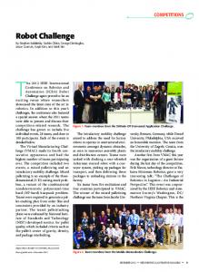
Fig. 1. Generic control architecture designed according to the proposed approach.
II. DESIGNING A CONTROL ARCHITECTURE ACCORDING TO THIS APPROACH Fig. 1 shows the structure of a control architecture designed according to the approach here proposed. There, the two DIFs are shown as a single block, for the sake of clarity. The figure also shows that the number of local filters is equal to the number of controllers involved in the fusion, thus meaning that the system is completely distributed. The set of controllers used in the control architecture depends on the specific application. In mobile robot navigation, at least one controller responsible for guiding the robot to the destination point (it implements the behavior goal seeking), which receives information from the internal sensors of the robot (odometry), should be present. This is just the first controller shown in Fig. 1, which also includes a set of other controllers (behaviors). As it can be seen in the figure, the individual controllers receive the sensorial information they are designed to deal with, either directly or through a fusion engine (also implemented using the DIF). Such data fusion is used either for a better environmental representation or for noise reduction. Each controller included in Fig. 1 generates its own signals for controlling the linear and angular speeds (the th controller ), each one feeding a Local Ingenerates the signals and formation Filter [1] of the respective DIF. Each Local Information Filter calculates its local Information Matrix and its local State Information Vector , which are fed to the Global Information Filter. This last component calculates the global Inand the global State Information Vector formation Matrix , which are fed back to each Local Information Filter. In the proposed approach, the decentralization is such that each Local Information Filter deals with the scalar values and , while each Global Information Filter deals with the scalar values and . The linear/angular speed sent to the robot, in this case, is calculated by dividing by . The combination of some Local Information Filters and one Global Information Filter is what is known as a DIF [6]. In addition, as the DIF is a stochastic estimator, a covariance measuring the confidence of the observed data should be assigned to each local filter. The output of the global information filter is closer to the output of the local information filter associated to the lowest
FREIRE et al.: NEW MOBILE ROBOT CONTROL APPROACH VIA FUSION OF CONTROL SIGNALS
covariance (the more reliable data, or the more reliable control signal, in this case). Finally, regarding the characterization described in [18], a control architecture designed according to the approach here proposed is a synchronous one, which presents continuous response codification for the linear and angular speeds, and the method used to coordinate the controllers (the behaviors) is the optimized fusion of their outputs through a DIF. A. Decentralized Information Filter The Information Filter [1] is essentially a Kalman Filter [17]. It is expressed in terms of measurements of information relative to some states of interest, instead of being expressed in terms of estimates of such states and the corresponding co-variances [1]. Then, the same result is obtained when applying either the Information Filter or the Kalman Filter, but the Information Filter has two major advantages in comparison with the Kalman Filter. The first one is that the initialization of the Information Filter (the definition of the initial value of the State Information Vector) is straightforward, while the initialization of the Kalman Filter depends on previous knowledge of the system or even on some luck [1]. The second one is that the Information Filter equations are simpler than the equivalent Kalman Filter equations [1]. A decentralized version of the Information Filter, the Decentralized Information Filter, is here adopted, once its use as fusion engine assures that the fused signals are as optimal as those generated by a Decentralized Kalman Filter, as well as that the computational effort to get them is decreased [1], [6]. There are two approaches to implement a decentralized filter. In the first one, the filter should be implemented using more than one processing unit [1]. In the second approach, the decentralized filter consists of a global filter and several local filters implemented in the same processing unit. The Decentralized Kalman Filter and the Decentralized Information Filter presented in [1] follow the first approach, while the Decentralized Kalman Filter presented in [17] follows the second one. The Decentralized Information Filter considered here, the same proposed in [6], also follows the second approach. B. Covariances Associated to the Inputs of the Local Filters When using an information filter, as well as a Kalman filter, to fuse sensorial data, a covariance is associated to each information source (each sensor), which expresses a statistical measurement of the confidence of the data it inputs to the filter [1]. In the fusion of the output of different controllers, in a similar way, it is necessary to associate a covariance to each control signal entering a local filter of the DIF, which now represents the degree of suitability of the respective controller to the current environmental condition. The lower the covariance associated to a certain controller is, the higher its degree of suitability is, which means that the control signals it delivers are more suitable to that environmental condition. Now, supposing that a reliable inference of the environmental condition is available at each time instant, from the information the sensing system onboard the robot provides, the designer can assign a degree of suitability to
421
each controller, which means to associate a covariance to each controller. The problem of modeling either the measurement error of a specific sensor or the noise included in such measurement is too complex. This is particularly true when the mobile robot is supposed to navigate in distinct nonstructured environments. In addition, it is frequent to have dynamic obstacles in the robot working-environment, whose evolution cannot be described by a deterministic or even stochastic process [2]. Thus, to obtain a statistical model of the sensors is quite difficult [15], and is not considered here. Nevertheless, the designer can consider the confidence of a certain sensor relative to other sensors, when associating a covariance to a controller, according to a previous knowledge of the robot working-environment. Consider, for example, that two controllers guide a mobile robot along a corridor. One is based on the information provided by a group of ultrasonic sensors, and the other is based on the difference between the optical flow measured on the left and right walls [20]. Ultrasonic sensors are known to be very sensitive to multiple reflections and cross talking, besides having low angular resolution, so that their measurements are not much reliable. On the other hand, the optical flow can be misinterpreted due to either inappropriate illumination or poor wall texture. Knowing the wall texture and the illumination pattern, the designer can associate a lower covariance (more importance) to the controller based on optical flow, once it is more adapted to the environmental condition. One can define the covariance associated to each controller by using different methods, always considering the data the robot sensors provide. The requisite is that the more suitable a certain controller is, the lower its covariance should be. A satisfactory way to calculate such covariances is based on fuzzy logic. Some linguistic variables are used to pack the designer’s knowledge about the robot navigation system and the robot workingenvironment into a rule base. This is the solution adopted in this work, and the covariances are calculated as shown in [7] and [8]. III. DESIGNING THE INDIVIDUAL CONTROLLERS This section presents four individual controllers that can be included in the general control architecture of Fig. 1. Actually, they are used in the particular control architecture designed to guide the robot in the experiment reported in Section V. The objective is to exemplify the methodology used to design the individual controllers, and to define the energy functions associated to them. All the controllers here discussed are based on information from ultrasonic sensors, the only sensorial apparatus used in the experiment reported in Section V. However, the approach here proposed to design control architectures is generic enough to include any kind of sensorial apparatus. Before addressing the design of the controllers themselves, the kinematic model of the mobile robot is presented. A unicycle-like robot positioned at a nonzero distance from the origin is considered. Its motion toward is govof the goal frame erned by the combined action of both the angular speed and the linear speed vector , which is always on the direction of one attached to the robot, as depicted in of the axes of the frame Fig. 2.
422
IEEE TRANSACTIONS ON SYSTEMS, MAN, AND CYBERNETICS—PART B: CYBERNETICS, VOL. 34, NO. 1, FEBRUARY 2004
Fig. 3.
Robot navigating in a corridor.
is proposed, where and are positive functions suitably selected to avoid the saturation of the control signal . The system closed-loop equation is then Fig. 2. Defining the position and orientation of the vehicle.
Then, the set of kinematical equations, which involves the of the vehicle and its orientation angle Cartesian position , is given by
(4) whose single equilibrium state is sider the Lyapunov candidate function
. Now, con-
(5)
(1) where is the magnitude of the linear speed vector, the distances and are measured with respect to the target frame , and is measured with respect to the orientation of the -axis of . frame This kinematic model is the reason to use two DIFs in the control architecture of Fig. 1: one DIF is responsible for generating the control signal for and the other is responsible for generating the control signal for . A. Controller to Navigate in a Corridor Consider the robot navigating in a corridor, as depicted in Fig. 3. The state variables considered are , the deviation from the middle of the corridor, and , the angular deviation relative to the corridor axis. In this case, the kinematic equations are reduced to
which is a positive definite function representing the summation of the potential energies due to the heading and position errors is selected of the robot along the corridor. Moreover, if such that [22]
where is a function of class [13], it can be verified that the integral term in (5) is radially unbounded, which means that is a globally positive definite and radially unbounded function. The time derivative of (5) is
where the rule of Leibnitz for differentiating an integral has been used. By using (4), one gets
(2) where it is assumed that the robot has a constant linear speed . Then, the control objective is to design a bounded control signal , which drives the states and asymptotically to zero. Then, the control law (3)
which results in the semi-definite negative function (6) Thus, one can conclude that the state variables and are bounded, and that is a square-integrable function. In order to verify the asymptotic stability of such a system, we exploit
FREIRE et al.: NEW MOBILE ROBOT CONTROL APPROACH VIA FUSION OF CONTROL SIGNALS
the autonomous nature of the closed-loop system (4) in order to apply the Krasovskii-LaSalle theorem [13]. In the region
the only invariant is . Therefore, by invoking KrasovskiiLaSalle theorem, it can be inferred that the origin of the state space is globally uniformly asymptotically stable. In order to limit the control signals, as proposed in [22], the and are defined as functions
where , , and are positive constants, so that , and , which was considered in the stability proof. Besides, the absolute value of the control signal is
Since and for all , all , and , then . , If and are chosen in such a way that for all , then the controller guarantees that which means that the control signal is bounded. Finally, the enis the Lyaergy function associated to this controller punov function given by (5). B. Controller to Follow a Wall It is possible to adapt the controller used to navigate in a corridor to make the robot to follow a wall, once such behaviors are very similar. This is done here by taking the variables (the same angle used in corridor navigation) and , the error between the robot current position and an imaginary line at a distance from the wall, as the state variables. The energy function is also the one given by (5), associated to this controller just changing by .
423
so that the resulting closed-loop equations are
where and are the linear and angular speeds, respectively, and is a proportional constant. It can be verified that this controller implements an asymptotically stable control system, asas demonstrated in [21]. Finally, the energy function sociated to this controller is given by (7)
D. Controller to Avoid an Obstacle The algorithm developed to avoid obstacles is based on the algorithm for the impedance-based control of mobile robots [21]. This control technique guides the robot from an initial point to (Fig. 2). Now, a local goal is defined one a destination point meter ahead of the robot in its motion direction, which does not influence the robot movement when it is going forward. However, if an obstacle is detected, it forces the robot to change its motion direction, so that it avoids the obstacle. To this aim, a is generated, as a function of the robot-obfictitious force stacle distance. Such a force has two components: , normal to the direction of movement, and , in the direction of movement. Then, a resulting force is calculated, which momentarily defines a change in the local goal position to allow the robot to avoid the obstacle. The stability of such algorithm is guaranteed, and the demonstration of such property is very similar to the demonstration shown in [21]. Thus, a stable control algorithm for avoiding obstacles is now is given by available, whose energy function (8)
C. Controller to Seek the Goal Position This controller is the one responsible for guiding the robot from a starting position to the desired goal position, as depicted in Fig. 2. The robot guidance is a result from combining a set of angular speed values and a set of linear speed values. The system state variables are , the distance between the robot current position and the goal position, and , the angle between the current robot heading line and the straight line connecting and (Fig. 2). Then, the robot mothe origins of frames tion can be described by
The proposed control signals are given by
where represents the angle between the current robot heading direction and the line connecting the robot center and the local goal. IV. STABILITY OF THE CONTROL SYSTEM This section presents a stability analysis of the control system of Fig. 1. Two basic assumptions are made: the structure of the robot working-environment is unknown, and the goal position is a reachable one. Another important aspect of this analysis is what one should mean by stability. The control system is said to be stable if the goal position is asymptotically reached, which means that the error between the current robot position and the goal position gets closer to zero along time, independently of the layout of the environment the robot is navigating in. This definition includes the property that the control system is capable of avoiding local minima, always considering that the goal position is reachable.
424
IEEE TRANSACTIONS ON SYSTEMS, MAN, AND CYBERNETICS—PART B: CYBERNETICS, VOL. 34, NO. 1, FEBRUARY 2004
As a result of such analysis, a conjecture is proposed, which guarantees the stability of the entire control system of Fig. 1, in the sense above mentioned. To guarantee that such conjecture is always accomplished, the block called supervisor is included in Fig. 1, which acts as an auxiliary for the two DIFs, as it will be detailed in this section. As part of the stability requirements, each controller used, when considered individually, should implement a control system that is stable in the Lyapunov sense. Thus, an energy function can be defined for each controller (a normalized Lyapunov function, in this case), as exemplified in Section III. An energy function is also defined for the entire control system, which is the sum of the energy functions associated to the controllers that are active at each instant of time. Thus, the energy function of the whole system is given by (9)
is the energy function of the th controller, and where represents the current state of the th controller ( stands for inactive). for active, and The supervisor is the subsystem responsible for determining the state of each controller. Actually, it performs three tasks. The first one is to label as inactive those controllers that are “out of context,” which means that their state variables are not available at that instant of time (such controllers are not useful, if this happens). It also monitors the energy function of the entire system and the energy function of each individual controller, in order to detect when the energy function of the system starts to grow. In this case, the supervisor labels as inactive each controller whose energy function is growing. As an example, consider a control system having two controllers, one responsible for seeking the goal and one responsible for following a corridor. Suppose that the robot should turn left in order to seek its goal, but it is in a corridor that drives it to the right. Then, the robot will go away from its goal, thus increasing the energy function associated to the controller responsible for seeking the goal, and the energy of the whole control system as well. Then, the supervisor labels as inactive the controller responsible for seeking the goal while the robot is in the corridor. Upon reaching the end of the corridor, this controller would be labeled as active again, restarting the goal seeking. Finally, the supervisor should also detect a change in the current navigation phase, and, upon detecting such a change, it should label all the controllers as active. A navigation phase is the terminology adopted to characterize a change in the current control objective. Regarding the aforementioned hypothetical situation, to follow the corridor represents one navigation phase, which changes when the robot reaches its end. While navigating along the corridor, the control objective becomes to follow the corridor and not to seek the goal, unless both objectives are not in conflict. At the end of the corridor, the control objective becomes to seek the goal once again. Thus, two distinct navigation phases are characterized in this example. Regarding the deactivation of a specific controller by the supervisor, an undesirable situation may arise, which corresponds
to the deactivation of all controllers available. Thus, the energy function assigned to the control system would become zero, which is not acceptable. In such a case, whenever a controller responsible for avoiding obstacles is available (that is the case in the experiment reported in next section), the supervisor always keeps it active. This way, the robot navigates, at least for a while, without any other objective than to avoid collisions. The task the robot should accomplish is to seek the goal position without colliding with obstacles or the walls closing the environment. The main concern is to guarantee that the robot reaches the final goal without knowing the environment layout a priori and in spite of the obstacles that can appear in its path. Two distinct possibilities are considered, for the analysis of the stability of the general control architecture of Fig. 1. In the first one, all the active controllers have a common control objective. As an example, suppose that the robot entered a corridor and, as discussed before, the supervisor has labeled the controller responsible for seeking the goal as inactive. Suppose also that no obstacle is present in the corridor, and that the control system has three controllers responsible for navigating along a corridor. This characterizes a control system having three controllers with the same control objective, possibly receiving information from different sensors. The second possibility corresponds to the more general case of different controllers having different control objectives. A good understanding of such case would come from the analysis of the entire path followed by the robot. In some parts, it seeks the goal, in other parts it follows a corridor, avoids an obstacle, follows a wall, etc. (like in the experiment shown in the next section). Both cases are analyzed in the next two subsections. For the first case, a proof of the system stability in the Lyapunov sense is presented, which means that the robot is always guaranteed to reach the goal in such a case. For the second case, an energybased conjecture is proposed, which guarantees that the entire control system presents a “good behavior,” in the sense that the goal position is reached. A. Stability of a Control Architecture With Controllers Having the Same Control Objective In this subsection, the stability of a control system involving the fusion of different controllers having the same control objective is analyzed. This particular configuration arises in situations where there are redundant controllers (similar controllers that use different sensorial information). As an example, in [15] a voting scheme is proposed to deal with the outputs of different controllers with the same control objective. In [20], a control system is proposed to guide a robot along a corridor, which performs the fusion of the outputs of two visual based-controllers. A proof that a control architecture designed according to the approach here proposed using only redundant controllers, like exemplified in [20], is stable is now presented. To do that, assume that the controllers generate different control signals for the robot angular speed, while the corresponding linear speeds is the desired angular are kept constant. Now, consider that is the angular speed, is the measured angular speed, and speed value that should be sent to the robot actuators to achieve , in spite of the robot dynamics.
FREIRE et al.: NEW MOBILE ROBOT CONTROL APPROACH VIA FUSION OF CONTROL SIGNALS
425
state variables associated to them are available at each instant of time, the set of individual control signals can be written as
Fig. 4.
Control system consisting of just one controller.
.. .
so that the control signal resulting from the fusion is (12)
Fig. 5. Fusing the output of different controllers having the same control objective.
Now, assume that an ideal control command corresponds to an ideal , such that
As a first step, assume that only one controller is used, as depicted in Fig. 4. Then, consider that the dynamics of the robot angular speed is modeled as
.. .
which results in (13) so that
can be written as
By making (10) equal to (12), one gets after taking (13) into account (10)
, and, finally,
(14) Now, from (11) and (14) it is possible to write the dynamics for the error in the angular speed as
Now, using an inverse dynamics control law [10] given by
(15) or, by defining the state vector where (16) where (11) the closed loop equation, for the exact knowledge of the robot . Then, replacing in the control dynamics, is given by law expressed in (11), one gets
Now, one can notice that the system described by (16) has an ultimately bounded solution [10]. This means that there are and such that for each there is a positive for which constant
which implies that the error in the angular speed as (because the individual controller is stable). Now, if more than one controller with the same control objective is used, as depicted in Fig. 5, and supposing that all the
where is the ultimate bound. To check that, consider the Lyapunov candidate function
426
IEEE TRANSACTIONS ON SYSTEMS, MAN, AND CYBERNETICS—PART B: CYBERNETICS, VOL. 34, NO. 1, FEBRUARY 2004
and its time derivative (17) where
Now, by taking the following bounds on both terms of (17)
one can write (18) from where
and
with
. Finally, it results
so that the ultimate bound [10] of the system described by (16) is given by
Using a control architecture designed according to the approach here proposed, since the fusion of the control signals is performed using the DIF (which is an optimized fusion method, like the Kalman filter [1]), the ultimate bound of the standard is smaller than it would be if just one deviation of controller were used. This means that the error in the angular speed converges to a limited region in a finite time (and remains there), as well as that the dimension of such region is smaller than the dimension of the similar regions corresponding to each individual controller used in the fusion process. B. Stability of a Control Architecture With Controllers Having Different Control Objectives When the controllers involved in the fusion process do not have the same control objective, the stability analysis carried out in the previous subsection is no longer valid. In this case, a conjecture based on navigation phases and on the energy-function associated to each controller is here proposed, which guarantees that the robot will always reach its final goal. A first step is to consider that the robot goes through several navigation phases while seeking its goal. A navigation phase is a part of the path followed by the robot in which just one control objective dominates. If the control objective is changed, a navigation phase is over, and a new one starts. The control system detects a change in the navigation phase when the energy
function associated to at least one of the controllers grows. Examples of navigation phases are wall following, obstacle avoidance, corridor following, goal seeking, etc. Thus, an important detail when designing a control system using the approach here proposed is that at least one controller corresponding to each distinct navigation phase the robot will face should be provided. Now, by regarding the stability of the individual controllers used, the overall system energy function is supposed to decrease while the robot remains in the same navigation phase. In order to ensure this, the supervisor included in the control architecture monitors the energy function of each controller and the energy function of the entire system as well. Then, if the energy function of the entire system starts growing, the controllers whose energy functions are growing are eliminated from the fusion process. Notice that this is equivalent to make their covariance infinite, so that the supervisor really acts as an auxiliary to the DIFs, as commented before, and not assuming the task of behavior coordination. Since the environment is unknown a priori, the kinds of navigation phases the robot should pass through to accomplish its task are unknown, as well as their number. It is also impossible to know the exact instant at which a navigation phase change will occur. Because of this, a transition between two navigation phases is characterized as a perturbation. For this reason, the system energy function is allowed to grow during the transition between two subsequent navigation phases. The conjecture we propose, which was validated through several experiments, is that the stability of the whole control system is assured if its energy function is constrained to decrease during each navigation phase, although it can grow in the transition between two subsequent navigation phases. V. EXPERIMENTAL RESULTS In order to evaluate the performance of a control architecture designed according to the approach here proposed, and to check the accomplishment of the stability conjecture, a practical experiment is now considered. It consists of guiding a mobile robot from an initial point (at coordinates [0 m, 0 m]) to a destination point (at coordinates [5 m, 5.5 m]) in an office floor whose layout is given in Fig. 6. Once more, it is important to emphasize that the robot does not know the environment layout. It only knows the coordinates of the initial and destination points. The experiment was run using a Pioneer 2-DX differential drive mobile robot having sixteen ultrasonic sensors, from which only ten are effectively used. A 500 MHz K6-II computer is available onboard the robot, which runs the control system of Fig. 7, specifically designed to guide the robot during this experiment. Three indexes proposed in [14] have been considered to evaluate the performance of the control system during the experiment. Table I shows the values of such performance indexes, as obtained during the experiment, as well as their ideal values. The index safety indicates the minimal distance measured by the ultrasonic sensors along the entire robot path, thus indicating the effective risk of collision. Its ideal value is calculated considering only the environment structure. As the robot is a circular platform with a diameter of 40 cm and navigates in a corridor
FREIRE et al.: NEW MOBILE ROBOT CONTROL APPROACH VIA FUSION OF CONTROL SIGNALS
427
Fig. 6. Layout of the environment in which the robot should navigate.
Fig. 8. Energy function of the entire system and the changes of navigation phase.
Fig. 7. Control architecture used in the experiment.
TABLE I PERFORMANCE EVALUATION INDEXES
Fig. 9. States of the controllers during the experiment.
that is 140 cm wide, the ideal value of the safety index is 50 cm. Note that no obstacle is considered along the corridor when calculating this ideal value. As Table I shows, the robot navigation was quite safe during the entire experiment, once the robot kept itself quite away from any obstacle all the time. The index average linear speed, in turn, indicates the average linear speed along the robot path. In this case, it was fixed in 300 mm/s for every individual controller, which is the ideal value for such index. As it can be seen from Table I, the fusion of different control signals makes the robot navigate a little slower. The index smoothness in Table I is determined by calculating the average absolute value of the difference between the current and the previous robot orientation, thus showing how smoothly the maneuvers are executed. Its ideal value is calculated by considering the environment structure and the ideal robot path. As it can be inferred from Table I, the control architecture implemented effectively allows very smooth maneuvers.
Finally, Table I also presents the effectively traveled distance and the time elapsed during the experiment, in addition to their ideal values. In the case of the traveled distance, the ideal value is obtained from the knowledge of the environment layout. The elapsed time, in turn, is calculated by dividing the ideal traveled distance by the ideal linear speed. In addition to the indexes presented in Table I, Figs. 8–10 allow analyzing how the control architecture of Fig. 7 has behaved during the experiment. Fig. 8 shows the evolution of the energy function of the entire control system, as well as the changes of navigation phases detected by the supervisor. There, each needle in the bottom part marks the time instant in which a change of navigation phase occurred (notice the coincidence of the increases in the energy function of the system with the changes of navigation phase). Fig. 9 shows how the state of every individual controller of Fig. 7 evolved (1 means that the controller is active and 0 means the opposite), as determined by the supervisor. Notice that most time more than one controller is active, which makes clear that the effective behavior coordination is performed by the DIFs, and not by the
428
IEEE TRANSACTIONS ON SYSTEMS, MAN, AND CYBERNETICS—PART B: CYBERNETICS, VOL. 34, NO. 1, FEBRUARY 2004
robot reaches the opening to the left, a new change in the current navigation phase is detected, and all the controllers are labeled active again. Then, the controller responsible for seeking the goal takes the robot to the left, trying to reach the destination point, which causes the robot to face the left-side wall, which is avoided as an obstacle. Then, the robot follows the transversal corridor, until detecting the next opening. Finally, after passing through the first two corridors, the robot gets a position (at the second opening in its left side) from which the controller responsible for goal seeking can take it to the final position straightforwardly. Notice that whenever a new navigation phase starts all the controllers are labeled active. Otherwise, the robot would not reach the final goal after having the controller responsible for seeking the goal deactivated. VI. CONCLUSION Fig. 10.
Path followed by the robot.
supervisor. Besides, Fig. 10 shows the path the robot followed until reaching the final goal. Note that a circle centered at the goal position is defined in Fig. 10, whose radius is defined as a function of the distance traveled, which is used to compensate the final position for the odometric errors. In Fig. 10, each robot sketch is marked after an interval of 5 s, and the solid line drawn between two subsequent 5-s marks represents the trajectory of the robot center. From the figure, one can see that when the robot starts moving the controller responsible for seeking the goal tries to take the robot straightforwardly to the goal position. However, the robot follows the corridor to the right side, which means that the covariance assigned to the controller responsible for following a corridor is much smaller than that assigned to the controller responsible for seeking the goal. Despite of this, the controller responsible for seeking the goal is kept active, because its energy function keeps decreasing as well as the energy function of the entire control system (see Fig. 9). This is a good example of how the DIF can coordinate different controllers with different control objectives. When the ultrasonic sensing system detects an obstacle, a change in the current navigation phase (corridor following) occurs. Actually, several changes are detected by the supervisor, because of the measurement errors intrinsic to the ultrasonic sensors, as it can be seen in Fig. 8. The robot starts turning left to avoid the obstacle, when the left wall of the corridor is detected. Therefore, the robot turns right, but the obstacle in the middle of the corridor is not over, so that the robot turns left again. Finally, the obstacle in the middle of the corridor is over, and the robot starts to follow the left wall of such corridor, which characterizes another navigation phase (see Fig. 8). When the robot detects the wall in its right side, a new navigation phase change occurs, with the robot starting to follow the corridor. While following the corridor, the robot surpasses the horizontal coordinate of the destination point, and the energy function associated to the goal-seeking controller starts growing. Once the goal-seeking controller is not helping to reach the destination point anymore, such controller is labeled inactive by the supervisor. Otherwise, this controller would try to move the robot back to the point (5 m, 0 m), which represents a point of local minimum. When the
A new approach to design control architectures to guide a mobile robot is here presented, whose main paradigm is the theory of nonlinear systems. The behavior coordination method is the fusion of the output of some nonlinear controllers, and the fusion engine is the decentralized information filter (DIF), which fuses different control signals corresponding to the robot angular and linear speeds. Such selection has considered two major advantages of the DIF in comparison with the Kalman filter, the most classical fusion engine. A control architecture designed according to the approach here proposed has two main advantages in comparison with other control architectures available in the literature. One is that the fusion method used is an optimized method, and the other is that the fusion is performed directly on the output of the controllers (the robot linear and angular speeds), thus not demanding any pre-fusion processing. The stability of the resulting control architecture is also discussed, starting from the argument that the controllers whose outputs are fused are designed in such a way that they individually generate a stable control system. Also, some of these controllers may have the same control objective and others may have different control objectives. Actually, it is formally demonstrated that the fusion of the output of different controllers having the same control objective has an ultimately bounded solution. Moreover, the control signal resulting from the fusion is better than the output of each individual controller, in the sense that the standard deviation of the output of the DIF is lower than the standard deviation of the output of each individual controller. Then, the stability of the fusion of the output of different controllers with different control objectives is addressed, and a stability conjecture is presented which is validated through several experiments, one of them presented in the paper. The conclusion, based on the mathematical analysis and the experimental results here presented, is that the fusion of the output of different controllers ensures a good behavior of the navigation system. This means that the robot always reaches its final goal, either when obstacles appear along its path or when its working-environment determines a temporary deviation of the final goal. Another important feature is that the robot performs very smooth maneuvers during its navigation.
FREIRE et al.: NEW MOBILE ROBOT CONTROL APPROACH VIA FUSION OF CONTROL SIGNALS
REFERENCES [1] A. G. O. Mutambara, Decentralized Estimation and Control for Multisensor Systems. Boca Raton, FL: CRC, 1998. [2] A. Saffiotti, K. Konolige, and E. Ruspini, “A multivaluated logic approach to integrating planning and control,” Artif. Intell., vol. 76, pp. 481–526, July 1995. [3] D. Langer, J. Rosenblatt, and M. Hebert, “A behavior-based system for off-road navigation,” IEEE Trans. Robot. Automat., vol. 10, pp. 976–983, June 1994. [4] D. Payton, J. Rosenblatt, and D. Keirsey, “Plan guided reaction,” IEEE Trans. Syst., Man, Cybern., vol. 20, pp. 1370–1382, Nov. 1990. [5] E. Bicho and G. Schöner, “The dynamic approach to autonomous robotics demonstrated in a low level platform,” Robot. Auton. Syst., vol. 21, pp. 23–35, July 1997. [6] E. O. Freire, R. Carelli, V. Mut, C. Soria, T. F. Bastos-Filho, and M. Sarcinelli-Filho, “Mobile robot navigation based on the fusion of control signals from different controllers,” in Proc. 2001 Eur. Control Conf., Porto, Portugal, pp. 1828–1833. [7] E. O. Freire, T. F. Bastos-Filho, M. Sarcinelli-Filho, and R. Carelli, “A control architecture for mobile robots using fusion of the output of distinct controllers,” in Proc. 17th IEEE Int. Symp. Intelligent Control, Vancouver, BC, Canada, 2002, pp. 142–147. [8] E. O. Freire, T. F. Bastos-Filho, M. Sarcinelli-Filho, R. Carelli, and O. Nasisi, “A new mobile robot control architecture via control output fusion,” in Proc. XV IFAC World Congr., Barcelona, Spain, July 21–26, 2002. [9] G. Schöner and M. Dose, “A dynamics system approach to task level system integration used to plan and control autonomous vehicle motion,” Robot. Auton. Syst., vol. 10, pp. 253–267, June 1992. [10] H. K. Khalil, Non-Linear Systems, 2nd ed. Upper Saddle River, NJ: Prentice-Hall, 1996. [11] J. Rosenblatt, “DAMN: A Distributed Architecture for Mobile Navigation,” PhD. dissertation, Robotics Inst., Carnegie Melon University, Pittsburgh, PA, 1997. [12] J. Yen and N. Pfluger, “A fuzzy logic based extension to Payton and Rosenblatt’s command fusion method for mobile robot navigation,” IEEE Trans. Syst., Man, Cybern., vol. 25, pp. 971–978, June 1995. [13] M. Vidyasagar, Nonlinear Systems Analysis, 2nd ed. Upper Saddle River, NJ: Prentice-Hall, 1993. [14] P. Pirjanian, “Multiple objective behavior-based control,” Robot. Auton. Syst., vol. 31, pp. 53–60, Apr. 2000. [15] P. Pirjanian, H. I. Christensen, and J. A. Fayman, “Application of voting to fusion of purposive modules: an experimental investigation,” Robot. Auton. Syst., vol. 23, pp. 253–266, July 1998. [16] R. A. Brooks, Achieving Artificial Intelligence Through Building Robots. Cambridge, MA: MIT AI Lab., 1986. [17] R. Brown and P. Hwang, Introduction to Random Signals and Applied Kalman Filtering, 3rd ed. New York: Wiley, 1997. [18] R. C. Arkin, Behavior-Based Robotics. Reading, MA: The MIT Press, 1998. [19] R. C. Arkin and T. Balch, “AuRA: principles and practice in review,” J. Exper. Theor. Artif. Intell., vol. 9, pp. 175–189, Apr. 1997. [20] R. Carelli, C. Soria, O. Nasisi, and E. Freire, “Stable AGV corridor navigation with fused vision-based control signals,” in Proc. 28th Annu. Conf. IEEE Ind. Electron. Soc., Sevilla, Spain, 2002. [21] R. Carelli, H. Secchi, and V. Mut, “Algorithms for stable control of mobile robots with obstacle avoidance,” Latin Amer. Appl. Res., vol. 29, pp. 191–196, Oct. 1999. [22] R. Kelly and R. Carelli, “A class of nonlinear PD-type controllers for robot manipulators,” J. Robot. Syst., vol. 13, pp. 793–802, Dec. 1996.
Eduardo Freire was born in Aracaju, SE, Brazil, in December 1972. He received the degree in electrical engineering from the Federal University of Paraíba, Campina Grande, PB, Brazil, in 1995, and the Master and Doctorate degrees in electrical engineering from the Federal University of Espírito Santo, Vitória, ES, Brazil, in 1997 and 2002, respectively. He is currently an Associate Professor with the Department of Electrical Engineering of the Federal University of Sergipe, Aracaju, SE, Brazil. From 1999 to 2003 he was an Associate Professor with the University Tiradentes. His research interests are mobile robot navigation and sensor fusion.
429
Teodiano Bastos-Filho (M’95) was born in Feira de Santana, BA, Brazil, in 1965. He received the BSc. degree in electrical engineering from the Federal University of Espirito Santo, Vitória, ES, Brazil, in 1987, and the Doctorate degree in physical sciences from the Complutense University of Madrid, Madrid, Spain, in 1995. He is currently an Associate Professor with the Department of Electrical Engineering of the Federal University of Espírito Santo, Vitória, ES, Brazil. From 1989 to 1994 he was a Research Auxiliary at the University of São Paulo. His research interests are mobile robot navigation, sensing systems and signal and image processing. Dr. Bastos-Filho is a member of Brazilian Society of Automatics (SBA-IFAC).
Mário Sarcinelli-Filho (S’89–M’90–SM’01) was born in João Neiva, ES, Brazil, in April 1956. He received the BSc. degree in electrical engineering from the Federal University of Espírito Santo, Vitória, ES, Brazil, in 1979, and the Master and Doctorate degrees in electrical engineering from the Federal University of Rio de Janeiro, Rio de Janeiro, RJ, Brazil, in 1983 and 1990, respectively. He is currently an Associate Professor with the Department of Electrical Engineering of the Federal University of Espírito Santo, Vitória, ES, Brazil, where he coordinates the Graduate Program on Electrical Engineering. His research interests are mobile robot navigation, computer vision and signal and image processing. Dr. Sarcinelli-Filho is also a member of Brazilian Society of Automatics (SBA-IFAC).
Ricardo Carelli (M’76–SM’98) was born in San Juan, Argentina, in 1952. He graduated in electrical engineering from the National University of San Juan, Argentina, and received the Ph.D. degree in electrical engineering from the National University of Mexico (UNAM). He is currently Full Professor at the National University of San Juan and Independent Researcher of the National Council for Scientific and Technical Research (CONICET, Argentina). He is Adjunct Director of the Institute of Automatics, National University of San Juan. He also coordinates the PhD and Master Programs in Control Engineering at the same university. His research interests are robotics, manufacturing systems, adaptive control and artificial intelligence applied to automatic control. Dr. Carelli is also a member of the Argentine Association of Automatic Control (AADECA-IFAC).