Journal of Engineering Sciences, Assiut University, Vol. 37, No. 5, pp. 1181-1192, September 2009.
A NEW SWITCHING PATTERN FOR DIRECT TORQUE CONTROL OFA PERMANENT MAGNET SYNCHRONOUS MOTOR DRIVE A.A. Hassan, A.M. El-Sawy, Y.S. Mohamed, E.G. Shehata
[email protected] Electrical Eng. Dept., Faculty of Engineering, El -Minia University, Egypt (Received August 11, 2009 Accepted August25, 2009). This paper aims to enhance the performance of the direct torque control (DTC) of a permanent magnet synchronous motor drive. Direct torque control has several advantages such as fast transient response, less parameter dependence. It has no need either to pulse width modulation, current control loop or to speed sensor. However, the high torque and flux ripples content are considered one of the main problems of DTC. The two band hysteresis comparators of the torque and flux are the main reason beyond this problem. The inverter state does not change until the hysteresis outputs change. The slow change in the hysteresis output causes slow change in the inverter states which in turn increases the ripple content in motor torque. In this paper, a new switching pattern using non-hysteresis controllers and new look up table are proposed. Three band flux controller and five band torque controller are used instead of the conventional two band controllers. Zero and active voltage vectors are inserted into the conventional lookup table. The proposed technique neither needs additional measurements nor space vector modulation techniques. Simulation works are carried out to compare the performance of classical and proposed techniques. The torque, flux, current, and speed waveforms of the proposed and classical schemes are compared.
KEYWORDS: direct torque control, permanent magnet synchronous motor, torque and flux ripples, new switching pattern.
NOMENCLATURE Vabc v , v
three phase stator voltages
Load angle
moment of inertia
,
Ld
d-axis stator inductance
s
Lq
q-axis stator inductance
ˆs
Stationary axes stator flux components Amplitude of the reference stator flux vector Amplitude of estimated stator flux
D
damping coefficient
iabc
i , i
three phase stator currents Stationary axes current components
J
1181
α - β stator voltage components
1182
A. A. Hassan A. M. El-Sawy Y. S. Mohamed E. G. Shehata
P
number of pole pairs
Rs
stator resistance
Te
electromagnetic torque
TL
load torque
r r* e f
actual rotor speed reference motor speed angular stator flux position permanent magnet flux
1. INTRODUCTION Permanent magnet synchronous motor (PMSM) has received a large attention in recent years. It has several advantages such as high power per weight ratio, low rotor moment of inertia, and high power density. So, it is used in many applications where high performance operation is required. Different techniques are used for controlling the torque and flux of PMSM. One of the advanced techniques is the direct torque control [2-6]. The principle of the DTC is the direct selection of the inverter states based on the torque error, stator flux error, and stator flux angle [1]. The motor torque is controlled by controlling the amplitude and speed of the stator flux linkage. The stator flux is obtained from the integration of the back electromotive force, which is independent on the motor parameters except the stator resistance. Two band hysteresis controllers are used for torque and flux loops. Lookup table is used to decide the inverter switching state based on the output of the hysteresis controllers and the rotor position angle. The inverter keeps its states till the output of the hysteresis controllers or the rotor position change. The hysteresis controller output does not change till the error reaches the upper or lower band. Therefore, high ripples appear in the torque and flux waveform, especially at low speeds. Many literatures have dealt with the problem of torque ripple existence in induction and synchronous motors [6-16]. In [6], two band flux controller and triple band torque controller are employed. In [7], zero and active voltage vectors are inserted in the conventional switching table. However, the torque and flux waveforms in these researches are not improved significantly. A modified direct torque control scheme for PMSM is used in [8] to solve this problem. A reference flux vector calculator and a PIcontroller are used instead of the hysteresis controllers. However, large ripples appear at low speed. Also, the switching frequency is larger than that of the classical DTC, which means, larger switching losses in the inverter circuit. In addition, the proposed scheme has slow response than the classical DTC. Discrete space vector modulation is used also to solve the above problem [910] via employing five level hysteresis controllers and modified lookup table. However, the speed signal is required for that system. In [11], a constant switching frequency torque controller is proposed. However, this system needs two triangular waveform generators, two comparators, and PI controller which increase the complexity of the scheme. In [12], a root mean square torque ripple equation for induction motor has been derived. At each sample, an optimal switching instant which satisfy the minimum torque ripple is determined. However, the derived ripple equation depends on the motor parameters and the measured speed signal. In [13], predictive torque and flux are
A NEW SWITCHING PATTERN FOR DIRECT TORQUE……
1183
used to select suitable voltage vector and switching time at each sample. However, the predictive torque depends on the stator voltage, current, permanent magnet flux, and the rotor position. Intelligent controllers such as fuzzy or neuro-fuzzy controllers are used to solve the problem [14-16] but the torque and flux ripples are still high, and most of these techniques depend mainly on the speed signal. In this paper, a new switching technique is applied to improve the DTC performance of the PMSM. Three band flux controller and five band torque controller are used instead of the conventional two band hysteresis comparators. New look up table is designed to achieve the inverter optimum switching state. The proposed scheme does not require measurement of the rotor position or speed signal. No additional calculations or space vector modulation is needed, so the sampling time does not change. Simulation works are performed at different operating conditions to compare the performance of the classical and proposed DTC. The results obtained show significant improvement in the speed, torque, flux, and current waveforms of the proposed scheme.
2. CLASSICAL DIRECT TORQUE CONTROL OF PMSM For surface mounted PMSM (Ld = Lq) , the torque equation can be expressed as [2-3]
Te
3 P s f sin 2 Ld
(1)
For interior PMSM (Lq > Ld), the torque equation becomes
Te
3P s 4 L d Lq
[2 f Lq sin( ) s ( Lq Ld ) sin(2 )]
(2)
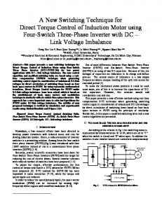
The two pervious equations show that the motor torque depends mainly on the amplitude of the stator flux and the load angle (δ) which is the angle between the stator and rotor magnetic axes. Figure (1) shows the stator and rotor flux frames where, α -β represents the stationary reference frame, x-y represents the stator flux reference frame, d-q represents the synchronous reference (rotor flux) frame. In steady state operation, the stator and rotor flux rotate at synchronous speed and the load angle (δ) is constant. In dynamic operation, the stator and rotor flux rotate at different speeds and the load angle varies. Since the electrical time constant is smaller than the mechanical time constant, the speed of the stator flux with respect to the rotor flux can be changed easily. This means that the load angle and in turn the motor torque can be controlled. The stator flux vector can be estimated as:
s (vs Rs is )dt
(3)
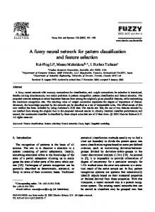
and i s are the stator voltage and current, respectively. If the stator resistance voltage drop is neglected, the stator flux vector can be controlled by controlling the stator voltage vector. The PMSM stator is fed from two level inverters. There is eight voltage vectors arranged as follows: V 0(0,0,0), V1(1,0,0), V2(1,1,0),V3(0,1,0),V4(0,1,1),V5(0,0,1), V6(1,0,1), V7(1,1,1). ). Six active voltage vectors are (V1-V6) and two zero voltage vectors are (V0,V7). The two zero vectors are located at origin. As shown in figure (2), the voltage vector plane is divided into six Where
vs
1184
A. A. Hassan A. M. El-Sawy Y. S. Mohamed E. G. Shehata
sectors. Each sector covers 60 degree. In each region, two active voltage vectors can be used to control the magnitude of the stator flux within hysteresis band. In classical DTC, zero voltage vectors are not used in PMSM to get quick torque response [2-5]. However, high ripples appear in the torque and flux waveforms. Lookup table for controlling the stator flux vector in each sector is shown in table (1) [2-8], where, , are the output of the torque and flux hysteresis controllers respectively and is the sector number. q
Y
s e
x
f
d
Fig. (1) Stator and rotor flux frames. V3
V4
V4
V5
3 V5
2 V2
V3 V6
4
V4
V5
5 V6
V3
V4
TEXT V5
V2
1
V3
V1
V2
V6
6
V1
V2
V1 V6
V1
Fig. (2) Stator flux and voltage vector in space vector plane Table (1) Classical switching states
=1 =0
τ =1 τ =0 τ =1 τ =0
1 2
3 4 5 6
V2 V6 V3 V5
V4 V2 V5 V1
V3 V1 V4 V6
V5 V3 V6 V2
V6 V4 V1 V3
V1 V5 V2 V4
A NEW SWITCHING PATTERN FOR DIRECT TORQUE……
1185
The block diagram of the DTC is shown in figure (3). The stator flux vector is estimated from the measured stator voltage and current as in equation (3). The motor torque is estimated from the measured stator current and estimated stator flux as given by the following equation:
Te 1.5P(i i )
(4)
The errors eT , and e are defined as the difference between the reference and the estimated values of the motor torque and stator flux. These errors are fed to the two band hysteresis comparators to give digital outputs (τ, Φ). The outputs of the hysteresis controllers and the number of sector (θ) are fed to the lookup table which selects the switching pattern to operate the inverter switches. Vdc
T +
Tˆ
eT
+
-
e
ˆ
Torque hystersis comparator flux hystersis comparator
S a ,b ,c Switching table
VSI
PMSM
i , i Torque and flux estimation
v ,v
i abc , v abc
abc / Transformation
Fig. (3) Block diagram of classical DTC scheme.
3. NEW SWITCHING PATTERN FOR DTC One of the main problems of DTC is the high ripple content in the torque and flux. As shown in figure (2), the band width of the comparators plays an important role in this problem. The output of the comparators still fixed till the error of torque or flux reaches the upper or lower band, and so, the comparator output and the inverter state change slowly. This is the main reason of the torque and flux ripples problem. In this paper, three band flux controller and five band torque controller are used. Also, non-hysteresis comparators are chosen. The flux and torque errors are divided to smaller regions to change the inverter states quickly. A new look up table has been established as shown in table (2). The bands of the torque controller are determined as follows: If e T < - 2* ε T then τ = 1 If -2* ε T ≤ e T < - ε T then τ = 2 If - ε T ≤ e T < ε T then τ = 3 If ε T ≤ e T < 2* ε T then τ = 4 If e T ≥ 2* ε T then τ = 5 Also the bands of the flux controller are determined as follows: If eΦ < 0 then Φ = 1
1186
A. A. Hassan A. M. El-Sawy Y. S. Mohamed E. G. Shehata
If 0 ≤ e Φ