IMAPS Nordic 2006 Gothenburg, Sweden, September 17-19
A New Technology for Elastic Electronic Circuits and Assemblies for Biomedical Applications F. Axisa1, I. Backers2, D. Brosteaux1, M. Gonzalez3, M. Vanden Bulcke3, K. Baert3, D. Gevaert2, J. Vanfleteren1 1
IMEC/TFCG Microsystems, Gent, Belgium 2 IMEC/KHBO, Oostende, Belgium 3 IMEC/MCP, Leuven, Belgium
phone +32 9 264 53 54, fax + 32 9 264 53 74 e-mail:
[email protected] url: http://TFCG.elis.ugent.be Abstract Electronic circuits for implantation in the human body or for use as intelligent band aid should ideally be stretchable and elastic for user comfort reasons. In this contribution the initial results of an MID (Moulded Interconnect Device) technology will be presented, showing the feasibility of simple functional stretchable electronic circuits. In the developed technology rigid or flexible standard components are interconnected by meander shaped electroplated metallic wires and embedded by casting or molding in a stretchable substrate material. The meander design was supported by mechanical simulations in order to minimize the stress in the metal during deformation. In this way stretchability of the circuits above 100% in one direction has been demonstrated. A simple stretchable thermometer circuit with 4 components embedded in Dow Corning Silastic® PDMS silicone material has been built and proper operation has been demonstrated.
Introduction Our daily life is more and more accompanied by electronic systems. Nowadays these systems show an increasing degree of complexity; however, this enhanced functionality may not lead to a decrease in comfort for the user. Therefore the increased complexity must be combined with advanced electronics packaging and interconnection solutions, so that compact and lightweight systems become available and do not hamper the comfort of the user. Ideally the electronics should be almost non-noticeable to the user. It is clear that in this perspective, the electronics should preferably take the shape of the object in which they are integrated. Therefore, there is currently a strong tendency to replace common rigid electronic interconnection substrates and assemblies by mechanically flexible equivalents. A further step is to not only ascertain the flexibility of the substrate, but also to make it stretchable. This emerging technology will be applied for biomedical electronics and for wearable electronics incorporated in clothes. Biomedical applications include implantable devices and electronics on skin. By making the electronic circuits stretchable, maximal comfort can be reached if the electronics behave like the tissue itself. The main challenge in making stretchable electronic circuits consists in the development of elastic conductors, interconnecting rigid or flexible islands which hold the components. Today metals are the best option to realize this type of interconnection with high performance and low cost. Few research groups [1-4] have recently reported work on the development of stretchable metallic interconnections on or in elastic substrates. In this contribution we propose an approach based on the one of Gray et al. [1]. The interconnection between two points is not a straight line but a
two-dimensional spring-shaped metal track.
Figure 1. Process sequence for metallic stretchable interconnections embedded in PDMS
2 mm
200 µm
(a)
150 µm
(b)
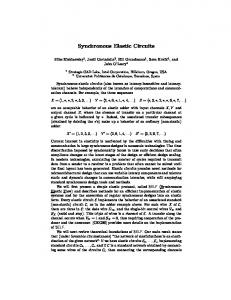
Figure 2. (a) Mask with patterns. (b) Principle and parameters of the applied circular based horseshoe shape patterns. Experiments/Method Stretchable metallic patterns The general process to embed tortuous metallic interconnections into a stretchable material is shown in figure 1. A photoresist is spin coated on a copper foil and patterned with the desired conductor shape by illuminating it (with UV) through a mask (figure 2(a)). In our study, the metal used is gold because of its high ductility and electrical conductivity. Furthermore, the chemical inertness of gold is an advantage for biomedical applications. From the processing point of view, the advantage of using gold is that it is not affected during the etching of the temporary carrier copper foil (figure 1, step 6). In step 3 of figure 1 a platinum seed layer followed by a 4 µm thick gold layer are electroplated. At last a Ni-Au finish is electroplated in order to be able to solder components on pad areas. Because current tends to concentrate in patterned areas [5] the pads have a grid pattern. When using plain contact pads, the deposition rate of gold on these pads is lower than on the tracks, resulting in a gold deposition thickness of more than 5 µm on the tracks and an inferior thickness on the pads. As stretchable substrate material polysiloxanes (silicones) are considered. They are used as IC device encapsulants and protection against moisture [6]. The most common silicones used in the electronic industry are polydimethylsiloxanes (PDMS). Some types have a soft and stretchable nature, conformable to tissues. Silastic MDX4-4210 from Dow Corning has been used, which is a biomedical grade silicone elastomer. It has a low Young’s modulus and a high elongation (470%). In step 5 of figure 1 the sample is overmoulded with the viscous (≥ 60,000 cP) silicone. After this the silicone is cured by placing the sample in an oven at 150°C (30 minutes). In step 7 of figure 1 the interconnection is embedded completely by applying another silicone layer. The total film thickness is about half a millimetre. A stretchable electronic circuit can be made if thicker silicone areas at the soldered components can protect them against excessive strain. Finite Element Analysis (FEA) has been used to optimise the shape of the conductors in order to allow high deformations without permanent damage. Even if simple conductor shapes like triangular or sinusoidal allow higher deformations compared to a straight line, they present a high concentration of stresses in the crest and trough, giving rise to early failures at fairly small deformations. Based on these results, a horseshoes like shape was designed.
Stresses are distributed in a wider region instead of being concentrated in a small zone. The horseshoe pattern is created by joining a series of circular arcs as shown in figure 2(b). Three different patterns were included in the mask design with a radius R of 450 µm and an angle H of 0°, 30° and 45° respectively. The induced stresses in the metal under deformation increase drastically if a wide metal track is used. In order to increase even more the stretchability of the conductors without sacrifying electrical performance, each conductor track has been split in four parallel lines. The single tracks have been made as narrow as the photolithography process allowed it with sufficient reliability, resulting in a width of 15 µm. The spacing between two single tracks is also 15 µm, making the whole “multitrack” 105 µm wide. On regular points, where the deformation will be minimal according to the simulations, neighboring single tracks are connected to each other in order to compensate single track interruptions caused by process faults or mechanical failure. MID encapsulation in a biocompatible stretchable matrix In order to provide a reliable way to embed components in a polymer, MID (Moulded Interconnect Device) strategy had been chosen. This technology consists in the encapsulation of the electronic system using a mould. If the electronic system is flexible, the result can be shaped in many ways. Using a mould enables to control thickness, to provide a 3D shape, and to shorten the processing time. However, the mould system should be adapted to the fact that the temporary copper substrate must be etched. So the MID has 4 steps (Figure 3.a). Firstly (Figure 3.a.a), the substrate with electroplated meanders and soldered components is maintained in place using a vacuum aspiration. The upper layer of PDMS is then injected and cured. Secondly (Figure 3.a.b), the vacuum plate is removed and the substrate is etched chemically. At this stage, the conductive meanders are only maintained by PDMS. Then another injection plate is mounted on the mould to inject the final layer of PDMS (Figure 3.a.c). After curing this layer at 150°C during 30 minutes the system is unmoulded to obtain the stretchable system (Figure 3.a.d). The mould system is thus composed of two injection plates, one vacuum plate and one ring plate for chemical etching (Figure 3.b). The material chosen for the plates was the polyetherimide ULTEM® 1000, based on its broad chemical resistance, its high heat resistance and its high mechanical strength and rigidity.
(a)
(b) Figure 3. (a) MID sequence for stretchable circuits. (b) Mould in 4 parts for the three steps of MID.
Figure 4. A moulded PDMS membrane of 500µm thick, with gold meanders embedded 250µm deep.
A result of MID is shown on figure 4. The moulded device is a PDMS membrane of 7cm x 7cm x 500 µm, in which gold meanders are embedded at precisely 250 µm.
Results and Discussion Influence of the meander shape The goal is to create stretchable interconnections which can support at least 50% and up to 100% elongation. These stretchable interconnections are planned to be used to link functional non-stretchable islands together in order to be able to create stretchable electronic systems for biomedical applications, in which common SMD components, platinum plated electrodes, antennas and flexible batteries are incorporated. The first step was to create interconnections with uniaxial stretchability or 1D stretchable interconnections. To test a single stretchable interconnection, connection wires are soldered on the pads at both ends of the stretchable interconnection. The length before elongation of an interconnection l is 3cm (length of the straight line between the two interconnection points). L is the length of the metal track (distance when following the meander shaped track). This means e.g. that L=(p/2)*l in the case that H=0. Characterisation of an interconnection is done using two parameters: - The resistance per running length unit of the interconnection with 0% of elongation r 0, (Ω/cm) r 0 is proportional to L/lIt was found experimentally that the total resistance R (Ω) of a track doesn’t significantly increase under stretch (see table I), where R = r0*λ. - The maximum elongation of a conductive stretchable interconnection Emax=100*(λF-λ0)/λ0 where λF is the length at which the interconnection fails and λ0 is the length without elongation. The theoretical maximum elongation of an interconnection is expected to be proportional to the ratio L/λ. Therefore we can define the quality Q of an interconnection as Q=Emax/r 0. Q represents the efficiency of a stretchable pattern.
Figure 5. Maximum elongation before failure in function of the resistance for the three different interconnection patterns. Figure 5 plots the maximal deformation of different samples with different patterns in function of r0. The three different patterns H0, H30 and H45 correspond to an angle H (Fig.2(b)) of 0°, 30° and 45° respectively. Some H30 and H45 samples remain conductive at a relative deformation of 100%. During those tests, the PDMS was not molded but cast. There is a large dispersion mainly due to the variability of process parameters. H0, H30 and H45 have a very low increase of resistivity during elongation (below 2% of increase after mid elongation). Mean Emax of H0 is 57%, of H30 75% and of H45 77%. The gain from H30 to H45 is very low with a sensible increase of r0. H0 has the higher quality (mean value 61 cm/Ω) and H45 has a significantly lower quality (see table I). Therefore, H0 is the best shape for low requirements in terms of stretchability, but H30 is an optimized shape for stretchable interconnections. However, a large dispersion is shown in Figure 5. When the elongation is above 50%, fabrication defaults affect definitively the reliability of stretchable interconnections and are responsible for 66% of the breaks (38% due to photolithography and gold electroplating defaults, 15% due to silicone thickness irregularity, 8% due to a bad soldering of the connection wires, and 5% due to manipulation errors). The dispersion can mainly be reduced by using a better electroplating methodology and by executing an optical verification of the electroplated patterns and the applied solder. Table I. Characterization result of different pattern for stretchable interconnection Type of Horseshoe
Resistance increase at mid-elongation (%)
Mean r0 resistivity (W/cm)
Mean Emax Elongation (%)
Mean Quality Q (cm/W)
H0
1,76
0,94
57,53
61,57
H30
1,19
1,86
74,82
40,73
H45
1,28
2,23
77,68
34,77
Stretchable interconnections and integration of SMD components in PDMS are possible using electrodeposition of a metallic pattern on a sacrificial layer, and embedding with a moulding technique. Using H30, we have a mean stretchability of 75%, a mean resistance of 1.9 Ω.cm, and a resistance increase of only 1.2% after mid-length elongation. However the reliability of the process is 75% for each 3cm interconnection with two pads, therefore only 50% of the stretchable LED circuits are functional. An increase of this rate will enable us to produce more complex
circuits. Stretchable electronic biomedical The first operating electronic circuit (figure 7) using this type of stretchable interconnection is a standard SMD mounted LED HSMC-S690, soldered on interconnection pads at one end of a 3 cm long interconnection, and linked with two other pads to an external circuit. The LED and the interconnection are embedded in 500 µm thick Silastic MDX4-4210 from Dow Corning. This circuit is very flexible, twistable and has a maximum stretchability above 60%. Pads and SMD component are protected from excessive strain with thicker silicone pad.
(a) (b) Figure 7. (a) Twistable blue LED circuit embedded in silicone and (b) operating under 35 % elongation. This Led circuit is a quite basic system, with all the components needed to obtain more complex circuits: interconnections, I/O ports, solderable pads and standard SMD components. The second step was to produce larger, functional, multi-component systems. The chosen system is a thermometer to monitor fever. This thermometer is composed of a head band to set it on the front and of a stretchable circuit with a temperature sensor to measure the skin temperature. The stretchable sensor circuit is attached to the head band. The whole system is a wearable healthcare monitoring system. This thermometer (Figure 8) is composed of a SMD embedded thermometer LM92 from National Semiconductor, a 0.33°C accurate 12bit temperature sensor with an I2C serial interface, with a current supply of 625 µA, and 8 pads. A decoupling capacitor, a resistor and a On/Off LED are also implemented in the stretchable circuit. PDMS is a thermal insulator, so we used the thermal properties of PDMS to ease the measurement. Firstly, the temperature sensor is placed as close as possible to the surface, in order to reduce the insulation layer, and enable the thermometer to measure the skin temperature as accurate as possible. A thicker layer of PDMS (4mm) on the top produces an efficient thermal barrier, which isolates the skin from the air. The thermal barrier induces an annihilation of thermal flow [7] and the skin temperature is then mainly correlated to the brain temperature after a latency of ten minutes. As it is meant for fever monitoring, this latency is not a problem. This sensor circuit is stretchable, and therefore easily integrated in a stretchable head-band in order to take all the advantages of smart clothes for biomedical systems [8]. Structurally, the PDMS layer has not a constant thickness, but a thickness of 1mm at the meander shaped stretchable interconnection, and 4 mm at the components and the I/O port to avoid them to be torn off when the sensor system is stretched. As the stretchable sensor circuit is embedded in a head-band, only one direction has to be stretchable and is indeed designed to be stretchable.
(a)
(b) Figure 8. (a)Stretchable thermometer for fever monitoring. (b)This sensor can be embedded in a wearable textile head band.
Figure 9. PC Display of the stretchable thermometer The sensor is connected to a PC via wires and a reception card. A software program collects the information, for calibration and for data acquisition (Figure 9). An alarm can be programmed. The next step in making a stretchable sensor system is the integration of a simple wireless communication system. Due to the softness and the stretchability of PDMS, the sensor is easy and comfortable to wear.
Conclusion We have developed a simple, low-cost process, using standard PCB manufacturing technologies, for stretchable interconnections with an elongation capability of up to 100%. Those stretchable interconnections can be used to produce stretchable electronic systems, using standard SMD components and soldering technologies. Embedded in biocompatible silicone like Silastic MDX4-4210 from Dow Corning, these systems can be implantable or be a part of a biomedical system. Moulding technologies applied to stretchable interconnections enable us to produce 3D stretchable systems, with any type of shape. Moreover different polymer types can be used for other types of applications like implantable biomedical systems, smart textiles, 3D shaped flexible or stretchable systems, strain absorbing systems, sensors, actuators, robotic skins, etc… Moreover functional design had been processed and tested for wearable biomedical systems. It is possible now to design more complex systems, including stretchable antennas and batteries, for wireless systems. Next step is to provide real isotropic (2D) stretchable systems, as only mono-directional stretchability has been proved, and to develop multilayer interconnections.
Acknowledgement The work was supported by the Institute for the Promotion of Innovation by Science and Technology in Flanders (IWT) through the SBO-Bioflex project (contract number 04101)
References
1. D. S. Gray, J. Tien, and C. S. Chen, “High-conductivity elastomeric electronics,” Adv. Mater., vol. 16, no. 5, pp. 393-397, Mar. 2004. 2. S.P. Lacour, J. Jones, S. Wagner, T. Li, S. Zhigang, “Stretchable Interconnects for Elastic Electronic Surfaces”, Proceedings of IEEE, Vol. 93, N°. 8, august 2005. 3. S.P. Lacour, J. Jones, S. Wagner, “Design and Performance of Thin Metal Film Interconnects for Skin-Like Electronic Circuits”, IEEE Electron Device Letters, Vol.25, N°4, April 2004 4. M.N. Maghribi, PhD Thesis LLNL, Preprint UCRL-LR-153347, 2003 5. T.A. Green, M.J. Liew, S. Roy, “Electrodeposition of Gold from a Thiosulfate-Sulfite Bath for Microelectronic Applications”, Journal of the electrochemical society, 150(3),C104-C110,2003 6. C.P Wong, “High Performance Screen Printable Silicone as Selective Hybrid IC Encapsulant”, IEEE Transactions on components, hybrids and manufacturing technology, Vol. 13, N°4, December 1990 7. F. Axisa, A. Dittmar, G. Delhomme, “Smart clothes for the monitoring en real time and conditions of physiological, emotional et sensorial reaction of human”, in Proc. 12th Annu. Int. Conf., IEEE Eng. Med. Biol. Soc., Cancun, Mexico, 2003, pp.297-301 8. F. Axisa, P.M. Schmitt, C. Gehin, G. Delhomme, E. McAdams, A. Dittmar, “Flexible technologies and smart clothes for citizen medicine, home healthcare and disease prevention”, pp 325-335, IEEE Transactions on information technology in biomedicine, Vol 9., N°3, September 2005


![Electronic Circuits [cir]](https://m.moam.info/img/260x300/electronic-circuits-cir_598d08321723ddd169542400.jpg)


