Advances in Intelligent Systems and Technologies Proceedings ECIT2008 – 5th European Conference on Intelligent Systems and Technologies Iasi, Romania, July 10-12, 2008
Chaotification of the buck converter using a modified Chua’s diode Nicu Bizon University of Pitesti
[email protected]
Abstract. The buck converter analyze, which is based on Chua’s diode in feedback loop, is presented. Complex behaviors are reported when the buck functional parameters are modified or the load has high dynamic, and different emergent routes to chaos appear. The Chua’s diode is usually used to generate chaos in electrical circuits. In this paper a modified Chua’s diode is used for voltage stabilization with low output voltage ripple, and power spectrum spreading using a simple chaotifying function. The switching command is obtained by variable gain of the output error voltage, using the modified Chua’s diode transfer characteristic, which is compared with chaotifying function. It’s a new way to obtain power converter chaotification, and to control the buck output voltage. Several work aspects of buck converter based on such switching rule are investigated by simulation.
1.
Introduction
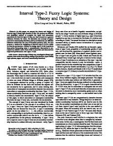
Pulse Width Modulation (PWM) technique is a usually technique to control the buck output voltage (figure 1). The imposed output voltage ripple can be obtained by filtering the output voltage through an appropriate capacitor, C, correlate with variable load, R (figure 2). An improved dynamic is obtained using a PI controller tuned by different classic or AI techniques (neuro-fuzzy, genetic algorithms etc.). The classical PWM feedback produces in stabilized regime a fixed switching frequency, fsw, which is the frequency of the saw-tooth voltage, used to obtain the PWM command for the buck IGBT switch (figure 3 and 4). The output voltage spectrum is concentrate at the switching frequency and its harmonics, generating high electromagnetic interference (EMI) (figure 5 and 6; as we know the output voltage ripple is higher if a low C capacity or/and low fsw are used) [1-3]. These high power spectrum peaks produce EMI and create major electromagnetic compatibility difficulties, so different techniques (randomize, chaotic etc.) that change the switching frequency and spreading the power spectrum peaks in a large frequencies band are proposed [4-13].
2
N. Bizon
Fig. 1. Buck converter with PWM voltage control using a PI controller
Fig. 2. Variable load (step or pulse)
Fig. 3. Buck converter structure
Fig. 4. PWM principle
FFT window: 3 of 10.87 cycles of selected signal
FFT window: 3 of 9.973 cycles of selected signal
10.71
11.2 11
10.7
10.8 10.69 10.6 10.68
10.4
10.67 0.03
0.035
0.04
0.045 Time (s)
0.05
10.2 0.03
0.055
0.035
0.1 0.08 0.06 0.04 0.02 0
0
5000
10000 Frequency (Hz)
15000
20000
Fig. 5. Output voltage ripple (top) and power spectrum (bottom): fsw=5kHz, L=20mH, C=47 F, R=22
2
0.045 Time (s)
0.05
0.055
DC component = 10.67 , THD= 2.74%
0.12
Mag (% of DC component)
Mag (% of DC component)
DC component = 10.69 , THD= 0.12%
0.04
2 1.5 1 0.5 0
0
1000
2000 3000 Frequency (Hz)
4000
5000
Fig. 6. Output voltage ripple (top) and power spectrum (bottom): fsw=1kHz, L=20mH, C=4.7 F, R=11
Chaotification of the buck converter using a modified Chua’s diode
3
There are many ways to investigate chaotic behavior in electronic circuits [7-13]. For example, one can examine the state space of variables (phase portrait), the time series of voltage and current (stroboscopic map), bifurcation diagram, power spectrum etc., in order to describe the dynamics associated with the nonlinear system. In this work we employ the power spectrum of the output voltage for a power spectrum spreading measurement.
2.
Proposed buck control and chaotification method
A new control technique that implies only a nonlinear controller in the buck feedback is proposed [14] and used in this paper (figure 7). The dynamics and stabilization performances (figure 8) not represent the objective of this paper, which present a new way to chaotifying the buck converter behavior using a simple function (figure 9; this function is easy to be implemented in a practical circuit, not as those proposed in [9-12], where complex chaotic techniques are based on MA/MF modulation of the output error voltage, Vo-Vref, chaos anticontrol, chaotic map transformation etc.).
Fig. 7. Buck converter with a Chua’s diode in the feedback loop
In: [-1,-0.6, -0.15, 0.15, 0.6,1] Out: [10,10,1,-1,-10,-10] Fig. 9. Function for Fig. 10. Lookup table for chaotification modified Chua’s diode
Fig. 8. Phase portraits: constant load (top), and step-load (bottom)
Fig. 11. Saw-tooth signal and output of the Chua’s diode
3
4
N. Bizon
The idea to use a nonlinear controller and a washout (high-pass) filter in the feedback loop in order to improve the buck performances isn’t new [12,15,16], but is all way associated with PWM switching principle (even if some voltage reference compensation and dynamic ramp compensation are doing). In this paper we chouse the saw-tooth signal as a function for buck behavior chaotification, and a modified Chua’s diode [17] as nonlinear transfer characteristic (figure 10) for output error voltage. The switching command is obtained by comparison of the signal used for buck PWM control chaotification, vsw, and Chua’s diode output, vCD (figure 11). Chua’s diode input is the output error voltage gained by Gv_error. We chouse to be a P controller in the feedback loop (not a PI controller, that improves the buck transient behavior for pulse load), in order to understand the influence of the buck time constants concerning power spectrum spreading. We define (see table 1) the associate frequencies: f LC 1 / 2 LC , f RC 1 / 2 RC , f LR R / 2 L and case conditions: C1 ( f LC / f sw