test their designs on real FPGA (Field Programmable Gate. Array) hardware via a remote connection. In this paper, we present the requirements for such a virtual ...
A New Virtual Hardware Laboratory for Remote FPGA Experiments on Real Hardware M. Reichenbach, M. Schmidt, B. Pfundt, D. Fey {marc.reichenbach, michael.schmidt, benjamin.pfundt, dietmar.fey}@informatik.uni-erlangen.de Department of Computer Science, Chair of Computer Architecture University of Erlangen-Nürnberg, Erlangen, Germany Abstract— E-learning systems become more and more important in higher education. But a lot of e-learning courses are only based on theory or simulations, making them inefficient and also uninteresting for students. Especially in the field of computer engineering, the experience of using real hardware is very important for the understanding of it. Therefore, we propose a virtual hardware laboratory where students are taught in circuit design, can simulate and finally test their designs on real FPGA (Field Programmable Gate Array) hardware via a remote connection. In this paper, we present the requirements for such a virtual laboratory, how we built the system and how it can be used. Finally, a complete e-learning course called FPGA online with practical exercises in an online laboratory was created and is now part of the Virtual University of Bavaria (vhb). Keywords: e-learning; virtual laboratory; FPGA Design; Remote Experiments; Circuit Design
1. Introduction The teaching of students in digital circuit design is a very hard and time consuming task. First of all, most students need quite a lot of time to understand the differences between a programming language and a hardware description language (HDL). Furthermore, the development and desktop environment for hardware design is very difficult for beginners. One way to get familiar with hardware development, is the usage of so-called FPGAs (Field Programmable Gate Arrays) which are a type of reconfigurable devices. They can be used to implement and test arbitrary hardware cicruits and have been used for prototyping purposes in hardware design for several years. An e-learning course about FPGA development with only theoretical background is not sensible, first of all for FPGA beginners. Therefore, we decided to realize an e-learning course with an online laboratory, because efficient learning in the field of hardware development requires a mixture of theoretical and practical exercises [1]. The reason is that for hardware engineering it is not sufficient to simulate hardware circuits only, because the real hardware behaves different from simulation [2], [3]. There are a lot of advantages for such a course. The students can work at home with their personal computers
with individual operating systems, editors and so on. They have access to the hardware of the laboratory 24 h a day. The laboratory can be realized very compact which saves a lot of space and also staff costs are reduced. The advantages of e-learning systems are not new and elearning in the field of engineering is used by a lot of other universities until now [4], [5], [6], [7], [8], [9]. But many of such e-learning courses are only theoretical or simulation based [10]. In order to realize a sensible e-learning course in the field of engineering and to take advantage of the reasons above, we decided to build an online FPGA laboratory for remote access, which we will present in this paper. The FPGA boards are connected to a server at the University and will be programmed by the server. The FPGA boards are monitored via cameras to see the state of the boards, e.g. blinking LEDs or information on an integrated display. To realize input signals by the user, an additional IO board is connected to each FPGA board. The advantage of such a system is that a few boards can be shared between lots of students, because not all students need a board at every time. Furthermore, the boards are protected from incorrect handling. The whole system is supported by a webportal for the lectures, exercises and tests. It is realized with the Open Source tool Moodle [11] used as Course Management System (CMS) and the lessons were created with eLML (eLesson Markup Language) [12] which is an Open Source XML framework for the realization of structured eLessons. The paper is divided into five sections. In the next section we describe the requirements of such a system and how to meet them. Afterwards, the creation of the e-learning content together with the used tools are presented. Section four describes the architecture of the system in a brief form. In the fifth section, the implememtation details are discussed. Finally, a conclusion and outlook are given.
2. Requirements For creating a new virtual hardware laboratory, it is important to fulfill some requirements. In this section, we will present the requirements which are most important for our e-learning course.
2.1 Learning Content One of the biggest advantages of e-learning systems is that they are available 24 h a day. To realize this, the content should be provided on a webserver with the help of a CMS. The CMS should support subjects, excercises and tests. The content should be available in different output formats for presentation on the web, but also for printing a hard copy for the students. Besides, if possible, all this should be done automatically to avoid a time consuming human interaction. Finally, to build a low cost system, the used tools should be Open Source and the content must be accessible with free and common tools (for example common browsers and PDF viewers). Because circuit design is a difficult task, it is neccessary to offer a direct help from a teacher. Therefore, a consultation hour via VoIP should be arranged. Additionally, mailing lists, a forum and also a chat for discussions should be used, for an efficient interaction with the students.
2.2 Technical Requirements As mentioned in Section 1, it is important that the students can work at home on their local computers. Hence, the tools for the practical exercises have to be installed locally by the students which has a big advantage. There is no need for a powerful server for hardware development which is also very important for the scalability of the system. But to realize this, the tools for practical exercises have to be available for the students for free and should be installable on different operating systems. For an interaction with the FPGA boards via a remote connection, we decided to use a monitoring with a camera system. Hence, there are additional requirements, because a connection via the internet is slow and has a big latency. Therefore, we have to choose a sufficient video codec which requires a low bandwidth only, but allows a monitoring of the board in a sufficient quality. A last important point is the access to the FPGA boards via a remote connection. The user must be able to set inputs to the FPGA board. Normally, this is realized by the pushbuttons and switches of the boards. But this is not possible with a remote connection and must be emulated. Hence, an additional IO board is required, which is connected to a FPGA board and can be controlled via HTTP. It allows to send signals to the interface of the FPGA board for an emulation of the pushbuttons and switches.
2.3 Resources Management For the management of the online laboratory, a server with a resource-management-tool is required. Because we have choosen a Linux server, we have implemented this tool as deamon, which we call VHBD (Virtual University of Bavaria Deamon). The main challenge is to arbitrate the access from many users to a limited number of boards. Every student should get the chance to use a board and after the usage, the access to the board has to be released. It is very important,
that there is no possibility to block a board for a greater amount of time. After a fixed time slot, a user should be banned for a short amount of time. For a remote connection, the topic of security has also be attended to. The VHBD has to be secured for incorrect access and in the best case, it uses security mechanisms of the underlying OS, in our case a secure Linux system. Finally, the deamon should generate logfiles and statistics.
3. e-Learning Content 3.1 E-learning Infrastructure The efficient creation and refurbishment of the e-learning materials plays a very decisive role in an e-learning course. Sustainability and longevity of the e-learning content and infrastructure is essential [13]. The content and infrastructure must be easily extentable, modifiable and also scalable for an arbitrary number of users. For the e-learning material it is important that different types of output formats are available, like a presentation for a website or a printable document format. It was also important for us to use Open Source software and tools to reduce the overall costs. Therefore, we decided to use the eLesson Markup Language (eLML) which is an open source XML framework for creating structured eLessons using XML [12] in combination with Moodle as a Open Source Course Management System (CMS) [11]. In the following, we will take a closer look at eLML, Moodle and we will give an overview of the content of our basic FPGA course.
3.2 eLML The eLesson Markup Language (eLML) is a XML based framework and was published as an Open Source project under the GPL [14]. The pedagogical concept behind eLML is the ECLASS model from Gerson [15], where ECLASS is an acronym for entry, clarify, look, act, self-assessment and summary. This model was combined with a lot of other important elements which makes eLML very flexible for the creation of e-learning courses. The top-level elements of the eLML structure are illustrated in Figure 1 [12]. Every lesson starts with the element entry with a short introduction about a lesson and the element goals with a summerization of the learning goals for this lesson. The content of a lesson is distinguished in several units. The elements entry and goals are provided optionally for units. Every unit consists of learningObjects which are described with the elements clarify, look and act. The clarify element contains the theoretical background of a topic, the elements look and act can be used for the presentation of an example. A lesson can be finished optionally with a selfAssessment, summary and some other elements, like glossary or bibliography. All dahsed boxes of Figure 1 are optional features of eLML.
Fig. 1: Basic eLML Structure
The main reason for using an XML framework is the availability of different output formats which is mandatory for an e-learning course. By XSL Transformation, the XML description of the material can be transformed to (X)HTML for an online presentation on a webserver or to PDF as printable document. Furthermore, eLML provides the formats SCORM and IMS CP for the integration in a Course Management System (CMS) like Moodle.
3.3 Moodle Server Moodle is an Open Source Course Management System (CMS) [11]. Nine different e-learning platforms were analyzed in detail in [16] and Moodle obtained the best results. It can be installed on a webserver and provides an interactive platform for the e-learning materials. It contains also a discussion forum, a calendar, a news section and a Wiki. Furthermore, Moodle supports a lot of additional plugins and a user can write own modules in PHP. So far, there are several thousand registered sites which are using Moodle [17] as CMS.
3.4 Extend eLML and Moodle Server For our practical circuit design course, we required VHDL source code examples in the content of the lessons. But eLML provides only a simple code environment and does not support source code with syntax highlighting. Also the usage of colors, for a manually formatting of source code, is not supported. On the other side, it is not a good practice to use source code screenshots in the content because there is no possibility to mark or copy code subsets of the examples. Therefore, we extended the standard eLML package by creating new rules in the transformation scenarios for html
and pdf. A code environment was added and we implemented XML tags for colors, a non-breaking space and a line wrap. With these new features, it is possible to format the VHDL source code manually. But this is complicated and very time-consuming. Therefore, we developed a tool which transforms a given VHDL code file, into well formatted XML code. In this process, every space is converted in a non-breaking space to allow indenting. Special VHDL keywords are embedded between color tags to realize syntax highlighting which results in a clearly arranged code. The transformation tool is written very flexible and uses regular expressions and color patterns in external configuration files. This allows an easy adaption for other programming languages, like C code which is required by us for another online course. After the XML file, which contains the well formatted source code, was produced, it can be integrated in a lesson utilizing XInclude [18]. To publish a lesson on the Moodle Server, several steps are required. First, the XSL transformation and generation of so called IMS content packages from the transformation results has to be realized. After that, the package has to be uploaded to the server and, finally, the package has to be deployed via the web interface. Doing these steps manually for every lesson is a very time-consuming task. To automatize this procedure, it was necessary to write some scripts which execute the tasks above, every time the sources on our repository were changed. In this context, the big challenge was the deployment of the IMS packages, because commonly, this can be done only via the web interface. Therefore, we have written a new plugin for the Moodle Server which allows an autodeployment of changed packages.
3.5 Course Content Our e-learning course, which will be provided by vhb, is a basic course for FPGA beginners. It is intended for bachelor students but also for employees which are interested in using FPGAs for hardware development. The course starts with an historical overview about programmable devices. After that, the basic structure of an FPGA is presented in detail. In our course, VHDL (Very-high-speed integrated circuits Hardware Description Language) is used for designing hardware circuits for FPGAs. Therefore, we integrated some compact lessons about VHDL in our course. After that, the design flow is presented together with important information about the tools and the hardware infrastructure. In the main part of our course, several important hardware circuits are presented, how they have to be described in VHDL and how they are mapped to resources of the FPGA. In the practical excercises of the course, the students have to implement some of these circuits and test their designs in the online laboratory.
Fig. 3: Celeritous PICWEB IO Board
Fig. 2: Digilent Nexys2 FPGA Board
3.6 Development Tools The FPGA board, which is used in this course, contains a FPGA from the manufacturer Xilinx. Xilinx provides the free tools ISE Webpack and ISim Simulator for FPGA development. Hence, the students can install these tools and implement their FPGA designs at home. Also the simulation can be performed at their local computers at home. The testing of realized hardware circuits is done via a remote connection at the online laboratory.
4. Architecture After defining the requirements and presenting the content of our course, we will present our hardware system in more detail in this section.
4.1 FPGA Boards For our course, we have choosen the Nexys2 board [19] from the manufacturer Digilent. The Nexys2 board (see Figure 2) contains a modern and low cost Spartan3E FPGA [20] from Xilinx. The big advantage of the board are the visual outputs. It contains a 4-Digit 7-Segment display and 8 LEDs, which can be controlled easily by the user. Therefore, the students can get fast successes with simple hardware circuits e.g. adders and multipliers. The board contains also inputs e.g. switches and pushbuttons, but they can not be used remotely and have to be emulated, utilizing an additional IO board (later more). Normally, the board can be programmed via the JTAG interface of the board. This interface is also connected to a Cypress FX2 [21] chip for a USB connection. This connection is used for a remote programming of the boards.
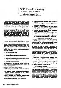
4.2 IO Boards and Connector Boards For a user interaction with the FPGA board, the so called IO board (see Figure 3) is used. It is a Celeritous PICWEB board [22], hosting a small webserver. Through a remote connection to a webpage of this server, the user has access to a virtual interface for the FPGA board. A connection to the board is established via the onboard ethernet interface and the power for the board is provided by a USB connector. To meet our requirements, the original webserver of the IO
Fig. 4: Connector Board beween FPGA Board and IO Board
board was adapted by us for an emulation of the pushbuttons and switches. This was accomplished by reprogramming the PIC microcontroller with a special PIC Programmer. To connect the IO boards with the FPGA boards, a connector board was designed by us which is shown in Figure 4. This board contains no logic, it only connects the IO Pins with the FPGA pins. With integrated resistors, this connection is short circuit protected which secures the hardware in case of a incorrect handling by the students. An additional LED per wire was added, to allow the student to observe the state of a wire.
4.3 Webcams For a monitoring of the hardware, a video stream will be sent to the user. To capture the video data, a low cost webcam from Logitech is used. The Logitech webcam C500 [23] has an integrated 1.3 mega pixel image sensor. With 30 frames per second at a resolution of 1280 × 1024, it is fast enough and the quality is sufficient for our purposes. The webcam uses an usb interface for a universal and easy use.
4.4 Server and Deamon We require two server systems for our course. The Moodle server provides the e-learning content, as described in Section 3.3. The second one is a resource management sever (RM Server), where all FPGA boards, IO boards and webcams are connected. The VHBD is installed on this server and runs the tasks, described in Section 2.3. Additionally, it compresses the video stream to reduce the transmitting latency. Hence, a more powerful server was required which is in our case a Intel Core i7 870 @ 2.93GHz CPU with 4 GB RAM. Because several boards and webcams
5. Implementation 5.1 FPGA Boards 5.1.1 Programming the Boards using UrJTAG
Fig. 5: Overall System
are connected to this server via USB, it contains additional USB cards, providing 30 USB slots.
4.5 Physical Architecture The physical architecture of our system is shown in Figure 5. On the top, there is the RM server with a monitor and a keyboard for simple debugging and maintenance. On the bottom, 10 FPGA boards, connected via the connector boards to the IO boards, are shown. Above the boards, the 10 webcams are mounted and every camera monitors one FPGA board. For an optimal illumination, there are two fluorescent tubes mounted in the box. Additionally, there is a switch on the left side of the box which connects the IO boards via ethernet with the RM server. The box has as small dimension of 80 × 80 × 150 cm. and stand on rolls, for flexibility and an easy movement.
4.6 User Workflow We have defined all system components and want to explain now, how a user can work with the system. Initially, he has to install all required tools on his local desktop computer. Then, he has to login on the moodle server and study the relating session content together with exercises and tests. After that, he writes VHDL code and implements a FPGA design with the tools installed on his computer. He has to generate a programming file for the Nexys2 board. The user has to login on the RM server and to upload the generated programming file. The VHBD programs the board and shows an address of a video stream and a website for the IO board input. The videostream can be watched in an arbitrary video player and the inputs can be controlled via a browser. All steps are fully OS independent and very easy to perform. As desired, all single steps could be plugged together in a common web interface.
One of our requirements was that only Open Source software and tools should be used on our servers if possible. Xilinx delivers with the ISE Webpack a programming tool called impact [24], as freeware but Closed Source. But this tool is only compatible with the Parallel-JTAGProgramming-Cable which uses a parallel port. For programming the board via USB, a special software from Digilent, the so called Adept Suite [25], is required. But this tool is also Closed Source. An Open Source tool called UrJTAG [26] is available for Linux based platforms. The problem is, that no driver exists for the Nexys2 board. But by reprogramming the Cypress FX2 chip on the FPGA board, it can be adapted and programmed via UrJTAG. This problem was already identified from other Nexys2 users and they have developed a new firmware for the FX2 chip [27] which emulates a USB Blaster device from Altera [28]. In conclusion, the JTAG ports from the FPGA will be controlled by the new firmware which emulates an USB Blaster interface. Now it is possible to program the FPGA with UrJTAG, but with one restriction. UrJTAG chooses the right driver according to the vendor and product IDs (VID/PID). After reprogramming the FX2 Chip, all FPGA boards have the same VID and PID. Hence, a distinction between the single boards is not possible. To solve this problem, we created for each FPGA board an own firmware with an unique VID/PID. This allows to set a special enviroment in UrJTAG which is able to identify the correct boards. For the creation process of the FX2 firmwares, some scripts have been created by us which automatically replace the PID/VID from the FX2 source code and, afterwards, compile it with the sdcc [29]. As VID the free ID 0x2357 for the Friedrich-Alexander-University Erlangen-Nuremberg (FAU) was choosen to avoid conflicts with other devices. The PID counts up, from 1 to n. 5.1.2 Identification of the Boards As mentioned before, the boards can not be distinguished by the server before reprogramming the FX2 chip. Also the serial number is zero at any time when new usb devices are detected. Hence, the server has no idea, which board is dedicated to a camera, respectively is connected to which IO board. To solve this problem, every FPGA is programmed, after reprogramming the FX2 chip, with an unique circuit which outputs the PID via the IO Pins to the IO board. Because the IO board has a fixed IP address, every IO board can be read out by the server to get the unique ID. In conclusion, it is possible to distinguish the boards and to determine the assignment of every board to a webcam. This problems occurs only at a startup or restart of the system
Fig. 6: FPGA-, Connector- and IO Board
and will not occur during application. The induvidual circuit generation for the FPGAs is also done fully automatically, by replacing the specific lines in the source code, afterwards, synthesizing and implementing it to a FPGA programming file.
5.2 IO Board and Connector Board There are three features, we had to implemented to fit our requirements. First of all, it has to be possible to write and read values from specific pins of the IO board. As mentioned before, the webserver of the IO board had to be adapted accordingly. As described in the previous section, the board IDs can now be read via a http-request by the server. To set the values of the input pins of the FPGA, the user has to connect to the webpage on the IO board and to set the emulated switches or pushbuttons on the virtual interface of the webpage. Secondly, a major problem is the authentication of the users. Only the inputs of the board, which is assigned to the user, should be changeable. Therefore, the concept of Session IDs has been introduced. A random alphanumeric sequence of characters is set as key, to control an IO board. Without this sequence, which can be set to an arbitrary length, the user can not access the webpage and set the inputs. When a board is assigned to a user, the daemon generates a Session ID and initializes the specific IO board. The ID is then part of the URL of the IO board which is send to the user. Only requests with the proper session are allowed. To set the Session ID of the IO board itself, a master password is needed as part of the URL. This master password is also required when requesting the board ID. Thus, only the daemon can assign the Session ID and request the board IDs and only the user, to whom the board is assigned, can control it. A third feature are time constrained input signals. To generate inputs e.g. according to the PS/2 protocol which is required for some of the exercises, a sequences of inputs is required which is time constrained. Therefore, a sequence generator has been implemented which produces PS/2 protocol sequences out of user input characters submitted via the web interface. For the connector board, we have developed an own PCB Layout. It was manufactured in a two-layer technology and
only contains some wires and for every wire an indicator LED. Figure 6 illustrates such a board, connected on the one side to the PMOD connectors of the FPGA board where resistors for short circuit protection are integrated. On the other side, it is connected to the IO board. The connector board for the connection of the FPGA and the IO board contains wires for the emulation of 8 Switches, 4 Pushbuttons and 2 wires for the PS/2 protocol emulation. The board contains also 4 additional LEDs for the monitoring of the board identification and one power LED.
5.3 Server and VHBD For using a secure and flexible system based on Open Source, the resource management server is running on Gentoo Linux. The VHDB is written in C and is installed on the server. Thereby, all critial system tasks, like user management, are done with the help of the operating system. This results in a very stable and secure system. All resources come together at the VHBD. When the daemon is started, it reprograms the FX2 chips on the boards, followed by a reprogramming of the FPGAs and identification of the boards, as mentioned before. Then the server waits for user interactions. If a user wants to program a board, the server looks for the next free board, assigns this board to the user who has access to the board now. The user gets a Session ID and has a fixed amount of time for experiments. If the time is over, or the user has logged out, the board will be released and can be assigned again to a requesting user. If a user requires more time, he has the possibility to extend the current experiment session. Some other scenarios are implemented, too. For example, a user is able to allocate a board for a specific time period. If the user is logged in at this time, an allocated board will be assigned to him. The VHBD is programmed in a very modular manner. That means, every component of the system is an own process which communicates via IPC e.g. pipes. Hence, the system can be easily extended with more boards and maybe more servers. Then, only the pipes have to be replaced by sockets. Such a system is currently developed in cooperation with the University of Passau. Additionally, such a multi-process system allows a high degree of independence between the processes. Since every user has his own process, many users can work on the system in parallel. The Server has two network interfaces. One is connected to the internet, where the students can connect to the system to use the VHDB. The other interface is connected internally to the switch, where all IO boards are connected. If a user wants to make IOs for a special IO board, the request is always sent to the RM server. With the help of IP tables, the request is transformed and will be forwarded to the choosen IO board. By means of this feature, we are able to save public IP adresses.
5.4 Cameras The webcams are connected via USB to the server which also has the problem to distinguish the different cameras. But this distinction is easier than the distinction of the FPGA boards, because every used webcams has a unique serial number. After plugging in a camera, a new device (/dev/videoX) is automatically created. With the help of udev [30] and some rules, it is possibe to create logical mappings from the physical devices /dev/videoX to logical devices /dev/vhbcamx which are now in the right order. Hence, the daemon knows for example, that /dev/vhbcam0 is always the bottommost left camera. The devices will be controlled with video for linux 2 (v4l2) and streamed utilizing a video lan client. We have choosen a MPEG-2 encoding with a variable bitrate of 400 kbits/sec. This leads to a low required bandwidth with a sufficient video quality.
6. Conclusion and Outlook In this paper, we presented a new remote FPGA hardware laboratory for our e-learning course FPGA online. Because of the available practical exercises in the online laboratory, the students can learn important basics in circuit design more efficiently by testing their circuits on real hardware. Because of a modular structure, our system is secure, flexible and can be easily extended for a greater number of users. The initial costs for creating the course and the operating costs were greatly reduced by the consistent usage of Open Source software for the e-learning content and also for the online laboratory.
Acknowledgment The work was supported by funding from the Virtual University of Bavaria (vhb), a network of universities and universities of applied sciences of the Free State of Bavaria/Germany.
References [1] D. Hercog, B. Gergic, S. Uran, and K. Jezernik, “A dsp-based remote control laboratory,” Industrial Electronics, IEEE Transactions on, vol. 54, no. 6, pp. 3057 –3068, 2007. [2] L. Bello, O. Mirabella, and A. Raucea, “Design and implementation of an educational testbed for experiencing with industrial communication networks,” Industrial Electronics, IEEE Transactions on, vol. 54, no. 6, pp. 3122 –3133, 2007. [3] A. Rojko, D. Hercog, and K. Jezernik, “Power engineering and motion control web laboratory: Design, implementation, and evaluation of mechatronics course,” Industrial Electronics, IEEE Transactions on, vol. 57, no. 10, pp. 3343 –3354, 2010. [4] F. Zeiger, M. Schmidt, and K. Schilling, “Remote experiments with mobile-robot hardware via internet at limited link capacity,” Industrial Electronics, IEEE Transactions on, vol. 56, no. 12, pp. 4798 –4805, 2009. [5] M. Wu, J.-H. She, G.-X. Zeng, and Y. Ohyama, “Internet-based teaching and experiment system for control engineering course,” Industrial Electronics, IEEE Transactions on, vol. 55, no. 6, pp. 2386 –2396, 2008.
[6] W. Li, G. Joos, and J. Belanger, “Real-time simulation of a wind turbine generator coupled with a battery supercapacitor energy storage system,” Industrial Electronics, IEEE Transactions on, vol. 57, no. 4, pp. 1137 –1145, 2010. [7] L. Bello, O. Mirabella, A. Raucea, and L. Capetta, “Enel pilot: From a research testbed to a virtual educational laboratory,” Industrial Electronics, IEEE Transactions on, vol. 56, no. 12, pp. 4844 –4853, 2009. [8] G. Farias, R. De Keyser, S. Dormido, and F. Esquembre, “Developing networked control labs: A matlab and easy java simulations approach,” Industrial Electronics, IEEE Transactions on, vol. 57, no. 10, pp. 3266 –3275, 2010. [9] G. Donzellini and D. Ponta, “A simulation environment for e-learning in digital design,” Industrial Electronics, IEEE Transactions on, vol. 54, no. 6, pp. 3078 –3085, 2007. [10] J. Ma and J. V. Nickerson, “Hands-on, simulated, and remote laboratories: A comparative literature review,” ACM Computing Surveys (CSUR), vol. 38, no. 3, 2006. [11] Moodle. (2011) Moodle. [Online]. Available: http://moodle.org [12] J. Fisler. (2011) elml-elesson markup language. [Online]. Available: http://www.elml.ch [13] R. Weibel, S. Bleisch, S. Nebiker, J. Fisler, T. Grossmann, M. Niederhuber, C. Collet, and L. Hurni, “Achieving more sustainable e-learning programs for giscience,” Geomatica, vol. 63, no. 2, pp. 109–118, 2009. [Online]. Available: http://www.zora.uzh.ch/25589/ [14] J. Fisler and F. Schneider, “Creating, handling and implementing elearning courses and content using the open source tools olat and elml at the university of zurich,” in ISPRS Conference, Bejing, 2008. [15] S. M. Gerson, “E-class: Creating a guide to online course development for distance learning faculty,” Online Journal of Distance Learning Administration [online], vol. 3, 2000. [Online]. Available: http://www.westga.edu/ distance/ojdla/winter34/winter34.htm [16] S. Graf and B. List, “An evaluation of open source e-learning platforms stressing adaptation issues,” in Advanced Learning Technologies, 2005. ICALT 2005. Fifth IEEE International Conference on, 2005, pp. 163 – 165. [17] Moodle. (2011) Moodle statistics. [Online]. Available: http://moodle.org/stats/ [18] W3C. (2006) Xml inclusions (xinclude) version 1.0 (second edition). [Online]. Available: http://www.w3.org/TR/xinclude/ [19] Digilent, Digilent Nexys2 Board Reference Manual, 2008. [Online]. Available: http://digilentinc.com/Data/Products/NEXYS2/Nexys2_rm.pdf [20] Xilinx, Spartan-3E FPGA Family: Data Sheet (DS 312), 2009. [Online]. Available: http://www.xilinx.com/support/ documentation/data_sheets/ds312.pdf [21] Cypress, EZ-USB(R) FX2LP(TM) USB Microcontroller HighSpeed USB Peripheral Controller, 2011. [Online]. Available: http://www.cypress.com/?docID=27092 [22] Celeritous. (2011) Pic 18f67j60 web server module. [Online]. Available: http://www.celeritous.com/estore/PICWEB_Server_Kit [23] Logitech. (2011) Logitech webcam c500. [Online]. Available: http://www.logitech.com/de-at/38/5866 [24] Xilinx, iMPACT User Guide - 4.1, 2011. [Online]. Available: http://www.xilinx.com/itp/xilinx4/pdf/docs/pac/pac.pdf [25] Digilent. (2011) Digilent adept. [Online]. Available: http://www.digilentinc.com/Products/Detail.cfm?Prod=ADEPT [26] UrJTAG. (2011) Urjtag documentation. [Online]. Available: http://urjtag.org [27] K. Waschk. (2011) usb_jtag - usb jtag adapter firmware. [Online]. Available: http://ixo-jtag.sourceforge.net/ [28] Altera, USB-Blaster Download User Guide, 2011. [Online]. Available: http://www.altera.com/literature/ug/ug_usb_blstr.pdf [29] S. D. et al. (2011) Sdcc - small device c compiler. [Online]. Available: http://sdcc.sourceforge.net [30] kernel.org. (2011) The linux kernel archives udev. [Online]. Available: http://git.kernel.org/?p=linux/ hotplug/udev.git;a=blob;hb=HEAD;f=README