A Non-Destructive and Direction-Insensitive Method Using a Strain ...
Recommend Documents
A new method, called barrier-coupling method, for coupling light into ion-implanted waveguides is .... is placed on a motorized precision rotation stage. The.
1998), the Iceman (Murphy et al. 2003), and the famous Queen Nefertiti statue (Huppertz et al. 2009), amongst other artifacts, and microCT has been used to ...
Aug 15, 2018 - Xianhua Yin,1,2 Wei Mo,1 Qiang Wang,1,2 and Binyi Qin 3. School of Electronic Engineering and Automation, Guilin University of Electronic ...
Key words. reduced order modeling, nondestructive evaluation, eddy current methods ... loop control design 24 . ... current method is implemented is by placing a thin conducting sheet carrying ... example carrying a uniform current is placed above th
Pharmaceutical Manufacturing by Andrew Sage ... Improving the performance of
pharmaceutical microbiologi- ... methods used by twenty-first century
pharmaceutical manu- .... Encyclopedia of Rapid Microbiological Methods; Miller,
M.J., Ed.;.
damage by analyzing time-synchronized data samples from two end joints and computing the local .... The third tier consists of a cluster of battery-operated sensors and sensor nodes with low data storage and ... detect congestion and recover lost pac
monitored pressure and pH in 12-inch and 8-inch pipes. ... LeakfinderRT.7 It is a system composed of sensors, wireless signal transmission system, and a PC.
chemical and microbiological analyses ... after harvesting and post-mortem which results from ... chemical, microbiological, and sensory evaluation. (Olafsdottir ...
Keywords Resistance spot welding . Nondestructive quality evaluation . The electrode displacement signal . Radar chart . Decision tree classifier. 1 Introduction.
developed for nondestructive testing of printed circuit boards. The stress- strain state of .... a planar location test setup with four sensors. A diagram in Figure 1b ...
acetone and re-evaluated. Chlorophyll concentration was estimated following the Lichtenthaler's equations (A) [23] and the Arnon's equations (B) [24] as follows:.
10 A nondestructive online method for monitoring the i ... s by collecting and analyzing machine running data.pdf. 10 A
oil and gas industries, wind turbines, etc. Table 16.3 shows the .... manual and automated tap testing, thermography, and shearography. 16.4.1 Nondestructive ...
The analysis of reflected ultrasonic waves induced by oblique insonification of ..... from one side to the test laminate make these methods effective for practical ...
INTRODUCTION. Determining the concentration of fissile nuclear materials (NMs) in various samples is a pressing prob lem at most stages of their production ...
automotive (3D vibration dynamics, brake discs squealing) [1], aerospace (characterisation of defects on composite structural parts of aircrafts [2], analysis of ...
R. A. Higgins, D. W. Onstad and G. P. Dively. 1996. European corn borer ecology and management. North Central Regional Ext. Publ. no. 327. The blue region ...
A Strain-Based Method to Estimate Slip Angle and Tire ... - MDPI › publication › fulltext › A-Strain-... › publication › fulltext › A-Strain-...by D Garcia-Pozuelo · 2017 · Cited by 23 · Related articlesApr 16, 2017 — Mechanical Engineering Depart
applications of an innovative Stress-Strain Microprobe (SSM) system that utilizes an in-situ nondestructive. Automated ball Indentation (ABI) test technique to ...
Keywords: Nondestructive, transverse vibration, ... structive testing (NDT) tools for
evaluating the quality ... f natural frequency of transversely vibrating beam,.
suggest that leaf temperature measurements are a versatile, nondestructive way of ... nium leaf that is 4 inches wide might ... for 7 to 10 d at 25 °C. A cork borer.
Email: [email protected]. Abstract â A significant limitation to the applications of fiber. Bragg gratings (FBG) sensors is the sensitivity of the Bragg.
KRZYSZTOF MOLSKI and GRZEGORZ GLINKA. Institute of Cranes and Heavy Machinery Engineering, Warsaw Technical University, 02-524 Warsaw, ul.
A Non-Destructive and Direction-Insensitive Method Using a Strain ...
Jun 6, 2018 - Using a Strain Sensor and Two Single Axis Angle ... two single axis angle sensors to measure the corn stalk lodging resistance in the field.
sensors Article
A Non-Destructive and Direction-Insensitive Method Using a Strain Sensor and Two Single Axis Angle Sensors for Evaluating Corn Stalk Lodging Resistance Qingqian Guo 1,2 , Ruipeng Chen 1 , Xiaoquan Sun 3 , Min Jiang 4 , Haifeng Sun 1 , Shun Wang 1 , Liuzheng Ma 1 , Yatao Yang 1 and Jiandong Hu 1,2, * 1
Received: 26 April 2018; Accepted: 3 June 2018; Published: 6 June 2018
Abstract: Corn stalk lodging is caused by different factors, including severe wind storms, stalk cannibalization, and stalk rots, and it leads to yield loss. Determining how to rapidly evaluate corn lodging resistance will assist scientists in the field of crop breeding to understand the contributing factors in managing the moisture, chemical fertilizer, and weather conditions for corn growing. This study proposes a non-destructive and direction-insensitive method, using a strain sensor and two single axis angle sensors to measure the corn stalk lodging resistance in the field. An equivalent force whose direction is perpendicular to the stalk is utilized to evaluate the corn lodging properties when a pull force is applied on the corn stalk. A novel measurement device is designed to obtain the equivalent force with the coefficient of variation (CV) of 4.85%. Five corn varieties with two different planting densities are arranged to conduct the experiment using the novel measurement device. The experimental results show that the maximum equivalent force could reach up to 44 N. A strong relationship with the square of the correlation coefficient of 0.88 was obtained between the maximum equivalent forces and the corn field’s stalk lodging rates. Moreover, the stalk lodging angles corresponding to the different pull forces over a measurement time of 20 s shift monotonically along the equivalent forces. Thus, the non-destructive and direction-insensitive method is an excellent tool for rapid analysis of stalk lodging resistance in corn, providing critical information on in-situ lodging dynamics. Keywords: strain sensor; single axis angle sensor; corn stalk; equivalent force; lodging rate
1. Introduction Stalk lodging resistance has always been an important aspect of plant quality in corn. However, there is little accurate information on corn stalk lodging resistance due to experimental restrictions [1,2]. Stalk lodging is the breakage of the stalk at or below the ear, which may result in a loss in the yield at harvest [3,4]. The tissue of the corn stalk is destroyed in the process of stalk lodging, which affects water and nutrient transportation and photosynthetic efficiency [5–7]. It is generally known that lodging is largely influenced by the strength of the stalk, which is determined by the diameter of the internodes, the internodes’ distance, and plant height [8,9]. Selective breeding approaches were traditionally applied to improve stalk lodging properties; such approaches relied on counting the number of stalks that had already broken or lodged below the ear at harvest [10,11]. A severe wind storm may nearly Sensors 2018, 18, 1852; doi:10.3390/s18061852
www.mdpi.com/journal/sensors
Sensors 2018, 18, 1852
2 of 11
blow down an entire field of corn and leave corn seldom standing, and it is impossible to distinguish stronger corn varieties from weaker varieties [12]. Currently, the most effective method to evaluate the property of stalk lodging is a laboratory wind tunnel experiment. An intuitive proportional relationship can be obtained between stalk lodging resistances and wind speed in the laboratory, using wind tunnel experiments [13–15]. Although wind tunnel experiments can be used to determine the stalk lodging resistance in corn, they are not convenient for the in-situ quantitative analysis of stalk lodging properties. The strength of corn stalks was appraised by hydraulic machinery applied to crush a stalk, where both the stalk crushing strength (SCS) and rind penetrometer resistance (RPR) are commonly used to evaluate the mechanical characteristics of corn stalks [16,17]. However, mechanical measurements to test stalk strength are typically destructive and time-consuming methodologies (involving physically breaking or crushing the stalk). Thus, a stalk hardness meter was developed to evaluate stalk lodging properties [18–20]. Correlation analyses revealed that stalk flexural stiffness predicted 81% of the variation in stalk strength, whereas rind penetration resistance only accounted for 18% of the variation in stalk strength [21,22]. Moreover, the rind penetration resistance of stalks cannot fully reflect the influence on stalk lodging caused by the natural wind, and the measuring results from the stalk hardness meter are greatly dependent on the probe shapes [23]. Scientists also put forward a method to evaluate stalk lodging properties by measuring a force directly exerted on the corn stalk. However, the measurement results were largely subject to the direction of pull force, and many aspects of this method still needed to be improved [24,25]. More rapid gains in corn stalk lodging resistance could be achieved by developing testing methodologies that can predict stalk lodging properties in the absence of stalk lodging related weather events [26]. In order to solve these problems, an innovative method is proposed in this paper to quantitatively determine stalk lodging properties during the stalk lodging process, where an equivalent force is immune to the direction of pull force was used. The equivalent force can be used to evaluate the corn stalk lodging properties. The obtained data can be provided for agricultural scientists to infer the corn stalk lodging process and to effectively evaluate the affective factors. 2. Materials and Methods 2.1. Plant Materials Five varieties of corn labeled Zhengdan958 (ZD958), Xianyu335 (XY335), Yudan606 (YD606), Xundan20 (XD20), and Denghai605 (DH605) were available for these experiments (Figure 1). The measured agronomic traits are indicated in Table 1. One-way analysis of variance (ANOVA) was used to determine whether there were any statistically significant differences among the treatment means, which were obtained from five corn varieties with two planting densities. Different varieties of corn were grown in the Science and Education Farm of Henan Agriculture University, Zhengzhou (113.66◦ E, 34.76◦ N). Five varieties of corn were provided by the Henan Academy of Agricultural Sciences, Tieling Xianfeng Seed Research Co., Ltd. (Tieling, China), Henan Agricultural University, the Agricultural Science Research Institute of Xunxian, and Henan Shandong Denghai Seed Industry Co., Ltd. (Zhengzhou, China), respectively. Planting areas were used with a plant distribution of two planting densities, 60,000 plants/hm2 and 75,000 plants/hm2 . Each planting area was 6 m long with 6 rows 0.6 m wide. The same fertilization management was utilized during two periods of corn growth (organic matter of 10.8 g/kg, total nitrogen of 0.93 g/kg, available phosphorus of 25 mg/kg, and available potassium of 125 mg/kg). The corn stalks in the stage of silking (20 days before maturity) were arranged for these experiments from June to October in 2016 and 2017, respectively.
Sensors 2018, 18, 1852
Sensors 2018, 18, x FOR PEER REVIEW
3 of 11
3 of 10
Figure 1. Five of Henan Henan Agriculture Agriculture Figure 1. Five varieties varieties of of corn corn grown grown in in the the Science Science and and Education Education Farm Farm of University, Zhengzhou. University, Zhengzhou. Table varieties of of corn corn with with two two planting planting densities. densities . Table 1. 1. Agronomic Agronomic traits traits obtained obtained from from five five varieties Density
Plant Height Ear Height Stalk Diameter Internode Ear Height Plant Height Ear Height Stalk Diameter Internode Ear Height (H(H p)/mm (H e)/mm (D S)/mm Length (L i)/mm Coefficient (Ce) (He )/mm (DS )/mm Length (Li )/mm Coefficient (Ce) p )/mm 1 60,000 ZD958 2606.00 b 1080.00 b 23.10 a 71.00 c 0.40 bc 60,000 2606.00 b 1080.00 b 23.10 a 71.00 c 0.40 bc 1 ZD958 60,000 YD606 2603.00 1060.20 cc 23.20 aa 98.10 aa 0.41 60,000 2603.00bb 1060.20 23.20 98.10 0.41b b 22 YD606 60,000 2464.20dd 1183.10 23.40 94.00 0.48a a 33 XD20 60,000 XD20 2464.20 1183.10 aa 23.40 aa 94.00 abab 0.48 60,000 2702.20aa 1093.10 23.10 93.00b b 0.41b b 44 XY335 60,000 XY335 2702.20 1093.10 bb 23.10 aa 93.00 0.41 60,000 2538.00 c 1000.00 c 23.40 a 74.20 c 0.39 c 5 DH605 5 60,000 DH605 2538.00 c 1000.00 c 23.40 a 74.20 c 0.39 c 75,000 2620.10 b 1106.00 c 22.50 a 80.00 c 0.42 b 6 ZD958 75,000 ZD958 2620.10 1106.00 cc 22.50 aa 80.00 0.42 75,000 2652.00bb 1076.20 22.11 109.30c ab 0.42b b 76 YD606 75,000 2547.40bc 1272.00 21.60 111.00 0.50 87 XD20 75,000 YD606 2652.00 1076.20 ca 22.11 aa 109.30 aba 0.42 ba 75,000 2736.30ca 1140.60 22.50 95.10ab 0.42a b 98 XY335 75,000 XD20 2547.40 1272.00 ab 21.60 aa 111.00 0.50 75,000 2562.00 c 1030.60 c 22.60 a 78.20 c 0.40 c 10 DH605 9 75,000 XY335 2736.30 a 1140.60 b 22.50 a 95.10 b 0.42 b Note: The lowercase letters a, b, c and d in Table 1 indicate the significant differences between different corn 10 75,000 DH605 2562.00 c 1030.60 c 22.60 a 78.20 c 0.40 c
Sample Variety Density Sample (Plants/hm2 2) Variety (Plants/hm )
varieties for each stalk’s agronomic traits, including plant height (Hp ), ear height (He ), stalk diameter (Ds ), internode
Note: The lowercase letters a, b, c(Cand d inwere Table 1 indicate thethe significant differences between length (L ear position coefficient achieved by using Least Significant Difference (LSD) e ), which i ), and (the p-value < 0.05). Here, the from root surface to height tip of tassels. the distance p ) is the distance e isheight different corn varieties for plant each height stalk’s(Hagronomic traits, including plant (Hp), H ear (He), from root surface to node of top ear. The stalk diameter (Ds ) at mid-growth stages is measured by using a Vernier stalk diameter (D s ), internode length (L i ), and ear position coefficient (C e ), which were achieved by caliper. The internode length (Li ) is the average internode length of the stalk between the 3rd node and 4th node counting the Significant ground. The Difference ear position coefficient of theHere, ear height to the plant height. using thefrom Least (LSD) (the(Cp-value < 0.05). the plant height (Hp) is the e ) is the ratio distance from root surface to tip of tassels. He is the distance from root surface to node of top ear. The 2.2. Measurement Design stalk diameterSystem (Ds) at mid-growth stages is measured by using a Vernier caliper. The internode length (L i) is the average internode length of the stalk between the 3rd node and 4th node counting from the The measurement device was composed of separate circuit blocks marked with Master unit ground. The ear position coefficient (Ce) is the ratio of the ear height to the plant height.
and Slaver unit, and the photos of the corresponding electronic components are shown in Figure 2. From Figure 2a, the Master unit mainly consisted of a strain sensor (JLBS-5Kg), a single axis angle sensor 2.2. Measurement System Design (SCA60C-N1000060) perpendicular to the circuit board of the Master unit to keep the initial value (0◦ ) of The measurement device was composed of separate circuit blocksand marked withacquisition Master unit and β, a microcontroller (MCU) PIC24FV16KA304, a power supply module, a signal circuit. Slaver unit, and the photos of the corresponding electronic components are Master shown unit in Figure 2. From Accordingly, a radio frequency (RF) transceiver (NRF24L01) was used in the to receive the Figure 2a, theangle Master unit mainly from consisted of a strain sensor (JLBS-5Kg), a single axis angle sensor stalk lodging α transmitted the Slaver unit (Figure 2b), which consisted of another single (SCA60C-N1000060) perpendicular to the circuit boardto ofthe thecircuit Masterboard unit toofkeep the initial axis angle sensor (SCA60C-N1000060) perpendicular the Slaver unitvalue with (0°) the of β, avalue microcontroller PIC24FV16KA304, powersensor supply module, and a signal initial (0◦ ) of α. In(MCU) the Slaver unit, a single axisa angle (SCA60C-N1000060) and acquisition another RF circuit. Accordingly, a radio (RF) transceiver (NRF24L01) was usedtime, in the Master unit to transceiver (NRF24L01) werefrequency used to measure the stalk lodging angles in real which were later receive the stalk angleInα this transmitted from system, the Slaver (Figure 2b), which consisted of transmitted to thelodging Master unit. measurement bothunit high-performance microcontrollers, another single axisand angle sensor (SCA60C-N1000060) to the circuit board of the Slaver PIC24FV16KA301 PIC24FV16KA304, were chosen perpendicular with 12-bit high-precision analog/digital (A/D) unit with the initial (0°)atofthe α.highest In the Slaver unit, a single angle sensor (SCA60C-N1000060) converters, and theyvalue worked running speed of 16axis million instructions per second (MIPS) and anotherthe RFmeasurement transceiver (NRF24L01) were used both to measure the stalk in real time, to manage results. Furthermore, single axis anglelodging sensorsangles were marked with which later transmitted to theaxis Master In this measurement system, both high-performance arrows,were indicating that both single angleunit. sensors could measure angles ranging from −90◦ to +90◦ microcontrollers, andspecial PIC24FV16KA304, with could 12-bitbe high-precision from the direction PIC24FV16KA301 of the arrow. With this structure, the were valueschosen of the angle monitored in analog/digital (A/D) converters, and they worked at the highest running speed of 16 million instructions per second (MIPS) to manage the measurement results. Furthermore, both single axis
Sensors 2018, 18, x FOR PEER REVIEW
4 of 10
Sensors 2018, 18, 1852
4 of 11 angle sensors were marked with arrows, indicating that both single axis angle sensors could measure angles ranging from −90° to +90° from the direction of the arrow. With this special structure, the of the range angle could in adirection changeable range to 90°, whenabove the direction of the avalues changeable from 0be to monitored 90◦ , when the of the pullfrom force0was located the horizontal pull force was located above the horizontal plane. The instrumentation amplifier AD620 was utilized plane. The instrumentation amplifier AD620 was utilized to amplify the voltage signals obtained from to amplify the voltage obtainedvoltage from the strain sensor, due to The the output’s signals, in the strain sensor, due signals to the output’s signals, in millivolts. universalvoltage serial bus (USB) millivolts. The universal serial bus (USB) adapter chip CH340G was used to facilitate communication adapter chip CH340G was used to facilitate communication between the Master unit and a computer. between theBJ12864F Master was unitapplied and a tocomputer. module BJ12864F display the The module display theThe measurement results, inwas 128 applied columns to × 64 lines, in a measurement results, in 128 columns × 64 lines, in a 3-bit serial mode supplied by a unipolar voltage. 3-bit serial mode supplied by a unipolar voltage. By using this measurement system, the stalk lodging By using thispull measurement the force stalk lodging angle α, the pull force F, the equivalent force F’, angle α, the force F, thesystem, equivalent F’, and the angle β could be measured and displayed in and the angle β could be measured and displayed in real time. real time.
of the measurement device and the electronic components. (a) The Figure 2. 2. Photos Photos of the measurement device andcorresponding the corresponding electronic components. electronic components of the Master unit; (b)unit; the (b) electronic components of the Slaver (a) The electronic components of the Master the electronic components of the unit. Slaver unit.
2.3. Measurement Measurement Principle Principle of of Equivalent Equivalent Forces Forces 2.3. The schematic schematic diagram diagramof ofthe themeasurement measurementprinciple principleofofthe theequivalent equivalentforces forcesisisshown shown Figure The inin Figure 3. 3. From Figure 3a, the pull force vector F 1 or F 2 can be decomposed into two parts: a downward From Figure 3a, the pull force vector F1 or F2 can be decomposed into two parts: a downward partpart (or (orupward an upward along the corn a rightward perpendicular tocorn the corn The an part)part) along the corn stalkstalk and and a rightward part part perpendicular to the stalk.stalk. The two two vectors are independent of each other and have an influence upon the corn stalk in the bending vectors are independent of each other and have an influence upon the corn stalk in the bending process process pull force is on applied on the corn stalk. The sensing of theaxis single axis angle when thewhen pull the force is applied the corn stalk. The sensing directiondirection of the single angle sensors sensors is marked withon arrows on the surfaces of theand Slaver andunits, Master units, respectively. Theranging angles is marked with arrows the surfaces of the Slaver Master respectively. The angles ◦ to +90 ◦ are ranging −90° to +90° are measured reliably measured around the axistoparallel to the sensing where direction, from −90from reliably around the axis parallel the sensing direction, the ◦ wherereaches the angle when isthe arrow is uptovertically to theplane horizontal plane and angle +90reaches when +90° the arrow standing upstanding vertically the horizontal and the angle is ◦ the angle is −90° when the arrow is standing in the opposite direction. The circuit board of the single −90 when the arrow is standing in the opposite direction. The circuit board of the single axis angle axis angle sensor was set to be perpendicular toboard the circuit of unit the Master (Figure to sensor 1 was set to1 be perpendicular to the circuit of theboard Master (Figureunit 2a) to ensure2a) that ensure that direction the sensing theangle singlesensor axis angle always parallel to theplane horizontal the sensing of direction the singleof axis 1 wassensor always1 was parallel to the horizontal at the plane at the initial position, when it was applied to measure the angles β 1 or β 2 . In the case an initial position, when it was applied to measure the angles β1 or β2 . In the case of an upward pull of force pull force F1 (shown in Figure 3a), the angle β1, measured by the single axis angle sensor Fupward 1 (shown in Figure 3a), the angle β1 , measured by the single axis angle sensor mounted inside the mounted inside Masterand unit, was positive, theForiginal pull force F1 was obtained by the strain Master unit, wasthe positive, the original pulland force 1 was obtained by the strain sensor (JLBS-5Kg). sensor (JLBS-5Kg). The equivalent force F 1′ was calculated using theFfollowing formula: F1′ = F1cos(β1 The equivalent force F10 was calculated using the following formula: 10 = F1 cos(β1 + α). However, the + α). However, the angle β2 was in the case a downward force F3a), 2 (shown in equivalent Figure 3a), angle β2 was negative in the casenegative of a downward pullofforce F2 (shownpull in Figure and the and the equivalent force of F 2′ was also calculated by a similar formula: F 2′ = F 2 cos(β 2 + α). force of F2 0 was also calculated by a similar formula: F20 = F2 cos(β2 + α). Moreover, once theMoreover, pull force onceapplied the pullupon forcethe wasinelastic appliedbelt upon the inelastic belt through theMaster operator, both Master and was through the operator, both the unit andthe Slaver unitunit should Slaverbeen unitinshould have been in a straight line,unit because the Slavertounit connected to athe Master have a straight line, because the Slaver was connected thewas Master unit with non-rigid unit with a non-rigid and inelastic belt. Therefore, those cases indicated in Figure 3b cannot occur in and inelastic belt. Therefore, those cases indicated in Figure 3b cannot occur in actual applications actual applications due to In this special structure. In this experiment, the stalkwithin lodging due to this special structure. this experiment, the stalk lodging angles fluctuated theangles range ◦ ◦ fluctuated within the range of 0° to 40° in the vertical plane. In order to evaluate the stalk lodging of 0 to 40 in the vertical plane. In order to evaluate the stalk lodging properties, an equivalent pull properties, an equivalent pull force was calculated by Equationcaused (1) to by eliminate the interference force was calculated by Equation (1) to eliminate the interference the direction of the pull causedFor bystandardization, the direction of the the pull pullforce force.was Forapplied standardization, pullmm force wasthe applied at theabove level force. at the levelthe of 440 along corn stalk
β1 or β2 were monitored at the same time (Figure 3a). For both cases shown in Figure 3a, the equivalent pull forces can be written in the following expression:
F' = Fcos(β +α)
(1)
Sensors 18, 1852 the where2018, F denotes
5 of 11 pull forces, α is a positive value measured by the Slaver unit whose direction is insensitive to the pull force due to the special design. In the case of an upward pull force F1 (Figure 3a), the measured angle β is also always positive. However, the measured has a negative the ground. Accordingly, the stalk lodging angle and the angles β1 or β2angle were βmonitored at the value same under the action of a downward pull force F 2 (Figure 3a). The equivalent force F’ is consistently time (Figure 3a). For both cases shown in Figure 3a, the equivalent pull forces can be written in the perpendicular to the cornstalk to eliminate the influence of the direction of pull force. following expression: From the Figure 3c shown in the experiment by F 0 = F cosprocess, ( β + α) the stalk lodging angle α, monitored (1) the single axis angle sensor 2 (SCA60C-N1000060), was transmitted by RF transceiver 2 (NRF24L01), where denotes the pull forces, α is a positive measured1 by the Slaver in unit direction is which F was mounted inside the Slaver unit, to value RF transceiver (NRF24L01) thewhose Master unit. The insensitive to force the pull force due to the case ofand an upward force Fby 3a), 1 (Figure original pull F, measured bythe thespecial straindesign. sensor In (JLBS-5Kg), angle β,pull obtained the single the measured angle β is also always positive. However, angle β has a negative value axis angle sensor 1 (SCA60C-N1000060) mounted insidethe themeasured Master unit, were processed by using under the action of(PIC24FV16KA304). a downward pull force F2 (Figure 3a).results The equivalent forceforces F’ is consistently the microcontroller The measurement and equivalent were finally perpendicular to the cornstalk eliminate thescreen influence of the direction of pull force. displayed on the liquid crystal to display (LCD) (BJ12864F) in real-time.
Figure 3. (a) Schematic diagram for the evaluation of stalk lodging properties under the pull force Figure 3. (a) Schematic diagram for the evaluation of stalk lodging properties under the pull force exerted upon the stalk; (b) some cases cannot occur during the experiment process; (c) the working exerted upon the stalk; (b) some cases cannot occur during the experiment process; (c) the working schematics of the measurement system. schematics of the measurement system.
3. Results and Discussion From the Figure 3c shown in the experiment process, the stalk lodging angle α, monitored by the single axis angle sensor 2 (SCA60C-N1000060), was transmitted by RF transceiver 2 (NRF24L01), 3.1. Stability Results which was mounted inside the Slaver unit, to RF transceiver 1 (NRF24L01) in the Master unit. Figure 4a depicts themeasured measurement performed by the novel measurement The original pull force F, by theprocess strain sensor (JLBS-5Kg), and angle β, obtaineddevice, by the where single the Slaver unit was fixed on a corn stalk with an inelastic belt, which was also connected to the axis angle sensor 1 (SCA60C-N1000060) mounted inside the Master unit, were processed by strain using sensor by a hook during the field measurement. After theresults Slaverand unitequivalent and Master unitwere werefinally well the microcontroller (PIC24FV16KA304). The measurement forces affixed, operators pulled the hook with a well-distributed force to avoid high dynamic tension in the displayed on the liquid crystal display (LCD) screen (BJ12864F) in real-time. measurement process. In the current measurement system, an acquisition circuit with the strain 3. Results and Discussion
3.1. Stability Results Figure 4a depicts the measurement process performed by the novel measurement device, where the Slaver unit was fixed on a corn stalk with an inelastic belt, which was also connected to the strain
Sensors 2018, 18, 1852
6 of 11
sensor by a hook during the field measurement. After the Slaver unit and Master unit were well affixed, operators pulled the hook with a well-distributed force to avoid high dynamic tension in Sensors 2018, 18, x FOR PEER REVIEW 6 of 10 the measurement process. In the current measurement system, an acquisition circuit with the strain sensor had had to to be be monitored monitored with with the the weight weight of of the the Master Master unit unit enclosure enclosure (about (about 225 225 g) g) in in real-time. real-time. sensor The automatic zero-tracking calibration was run under normal operating conditions prior to applying The automatic zero-tracking calibration was run under normal operating conditions prior to applying the pull pull force forceon onthe thestalk. stalk.ToTo obtain adequate measurement to clearly understand the the obtain adequate measurement datadata so assotoasclearly understand the stalk stalk lodging process, the acquisition time of 0.1 s and the total measurement time of 20 s were set for lodging process, the acquisition time of 0.1 s and the total measurement time of 20 s were set for each each measurement. Inexperiment, this experiment, five different stalks of the corn varieties were used measurement. In this five different stalks fromfrom one one of the corn varieties were used to to conduct the measurement with the original pull force at different stalk lodging angles, α, which conduct the measurement with the original pull force at different stalk lodging angles, α, which ranged from from00toto45°. 45◦The . The coefficient of variations (CVs) of 39.1% 4.85%, shown in Figure 4b, ranged coefficient of variations (CVs) of 39.1% and and 4.85%, shown in Figure 4b, were were obtained the original pull force andequivalent the equivalent respectively. Compared the obtained from from the original pull force and the force,force, respectively. Compared withwith the CV CV of 39.1% obtained from the original pull force F, the measured equivalent force had a much lower of 39.1% obtained from the original pull force F, the measured equivalent force had a much lower CV CV4.85%, of 4.85%, along lodging angles that ranged from 0◦ to 45◦ . experimental These experimental of along withwith corn corn stalk stalk lodging angles that ranged from 0° to 45°. These results results demonstrate the equivalent less affected the direction the original pull force demonstrate that thethat equivalent force isforce less is affected by theby direction of theoforiginal pull force and and good has good stability in the corn stalk lodging process. The directionofofthe thepull pullforce forcelargely largely depends depends has stability in the corn stalk lodging process. The direction on the the equivalent force, instead of on the height height of of the the operators. operators.Consequently, Consequently,ininthe theproposed proposedmethod, method, the equivalent force, instead the original pull force, is utilized to evaluate the properties of corn stalk lodging. This decreases the of the original pull force, is utilized to evaluate the properties of corn stalk lodging. This decreases interference caused by the directions of the forceforce exerted on the stalks. the interference caused by varying the varying directions of pull the pull exerted on corn the corn stalks.
Figure 4. The pull force is exerted on a position of 440 mm above the ground and close to the fourth Figure 4. The pull force is exerted on a position of 440 mm above the ground and close to the fourth internode of the corn stalk. (a) The prototype of the measurement device applied in the field internode of the corn stalk. (a) The prototype of the measurement device applied in the field experiment experiment of corn stalk lodging under the action of pull force F; (b) the original pull force F fluctuated of corn stalk lodging under the action of pull force F; (b) the original pull force F fluctuated significantly significantly with a CV of 39.1% along with stalk lodging angles ranging from 0° to 45°, while the with a CV of 39.1% along with stalk lodging angles ranging from 0◦ to 45◦ , while the equivalent force equivalent force was much more stable (CV of 4.85%). was much more stable (CV of 4.85%).
3.2. Equivalent Forces Changed with Stalk Lodging Angles 3.2. Equivalent Forces Changed with Stalk Lodging Angles By using the measurement device, the equivalent force and stalk lodging angle were monitored By using the measurement device, the equivalent force and stalk lodging angle were monitored and stored continuously in flash memory, in real-time, during the corn stalk lodging process. In this and stored continuously in flash memory, in real-time, during the corn stalk lodging process. In this field experiment, five different corn stalks from different positions in the center part of the plantation field experiment, five different corn stalks from different positions in the center part of the plantation were chosen from each corn variety labeled Zhengdan958 (ZD958), Xianyu335 (XY335), Yudan606 were chosen from each corn variety labeled Zhengdan958 (ZD958), Xianyu335 (XY335), Yudan606 (YD606), Xundan20 (XD20) and Denghai605 (DH605), with two planting densities of 60,0002 (YD606), Xundan20 (XD20) and Denghai605 (DH605), with two planting densities of 60,000 plants/hm plants/hm2 and 75,0002plants/hm2. The equivalent forces, varying with the stalk lodging angle α, were and 75,000 plants/hm . The equivalent forces, varying with the stalk lodging angle α, were plotted in plotted in Figure 5, which were obtained from the results of five repeated measurements. Figure 5, which were obtained from the results of five repeated measurements. The typical lodging process against the measurement time t, under the pull force exerted upon the corn stalk, are illustrated in Figure 5a, while the equivalent forces, which varied with the stalk lodging angles obtained from five varieties of corn, are shown in Figure 5b–f, respectively. Obviously, it is noted that the maximum equivalent force from the planting density of 60,000 plants/hm2 is larger than that from the planting density of 75,000 plants/hm2. The measurement curves indicated in Figure 5 have non-smooth sections due to the presence of the uneven original pull force applied on the corn stalk, the non-uniform lodging speeds, or the jitter of original pull force that occurred during the process of stalk lodging. Conclusively, agricultural scientists could deduce the relationship between the stalk lodging angles and the equivalent forces during the process of corn stalk lodging from Figure 5.
Sensors 2018, 18, x FOR PEER REVIEW Sensors 2018, 18, 1852
7 of 10 7 of 11
Figure 5. (a) stalk lodging; lodging; (b–f) the Figure 5. (a) Pull Pull forces forces changing changing with with the the time time in in the the process process of of corn corn stalk (b–f) the equivalent forces varying with corn stalk lodging angles for the five corn varieties with two planting equivalent forces varying with corn stalk lodging angles for the five corn varieties with two planting densities, respectively. respectively.
3.3. Maximum Equivalent Forces The typical lodging process against the measurement time t, under the pull force exerted upon the corn Five stalk,different are illustrated in Figure 5a,stage while equivalent forces, which variedfrom witheach the stalk corn stalks in the ofthe silking (20 days before maturity), cornlodging variety 2 and angles obtained fiveXD20, varieties corn, arewith shown in Figure 5b–f, respectively. Obviously, it is75,000 noted (ZD958, XY335, from YD606, andofDH605), planting densities of 60,000 plants/hm 2 is larger than that 2, were measured that the maximum equivalent from force from 60,000 plants/hm plants/hm June the to planting October density in 2016ofand 2017, respectively. The average 2 . The were from the planting density of 75,000equivalent plants/hmforces measurement in Figure 5 have measured results of the maximum plotted incurves Figureindicated 6a. non-smooth sections duethat to the of equivalent the unevenforces original pull force applied on the corn stalk, Figure 6a indicates thepresence maximum obtained from both the different corn the non-uniform lodging speeds, or the jitter of original pull force that occurred during the process of varieties and the same variety with different planting densities are quite different. From the pull stalk lodging. Conclusively, scientistsplanting could deduce the the relationship the force stalk forces applied upon the corn agricultural stalks from different densities, maximumbetween equivalent lodging angles and equivalent forces duringofthe process of corn2,stalk from Figure 5. the is approximately 44the N for the planting density 60,000 plants/hm and lodging it is larger than that for planting density of 75,000 plants/hm2 (Figure 6a).
Sensors 2018, 18, x FOR PEER REVIEW
8 of 10
Moreover, under the same planting density, the maximum equivalent force from DH605 is larger 8 of 11 the equivalent forces obtained from ZD958 (75,000 plants/hm2), XY335, and YD606 are similar to each other. Summarily, the equivalent forces from the five varieties of corn with two planting densities of 75,000 plants/hm2 and 60,000 plants/hm2 show that the corn stalks from 3.3. Maximum Equivalent Forces a high planting density area have less tensile strength than those from a low planting density area. The higher equivalent of in thethe corn stalk, stronger lodging resistance the corn has. Five different cornforce stalks stage ofthe silking (20 days before maturity), fromvariety each corn 2 and 75,000 2) has a2 high Figure 6b showsXY335, that the corn variety DH605 (60,000 plants/hm variety (ZD958, YD606, XD20, of and DH605), withplants/hm planting densities of 60,000 plants/hm and 2 , were 2 and 75,000The 2) maximum equivalent force, but thefrom corn June variety of XD20in(60,000 plants/hm plants/hm 75,000 plants/hm measured to October 2016 and 2017, respectively. average has a low maximum equivalent force. measured results of the maximum equivalent forces were plotted in Figure 6a. Sensors 2018,others. 18, 1852 However, than the
Figure 6. 6. Comparison Comparison of of the the equivalent equivalent forces forces for for the the five five corn corn varieties varieties with with two two planting Figure planting densities. densities. (a) The maximum equivalent force measured by the measurement system for each variety of with corn (a) The maximum equivalent force measured by the measurement system for each variety of corn with different plant densities; (b) the box-plot for each variety of corn with different plant densities. different plant densities; (b) the box-plot for each variety of corn with different plant densities.
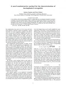
3.4. Field Stalk Lodging Rates Figure 6a indicates that the maximum equivalent forces obtained from both the different corn The and number of corn stalkswith thatdifferent had already broken or lodged belowdifferent. the ear at harvest was varieties the same variety planting densities are quite From the pull counted for the five corn varieties grown in the Science and Education Farm of Henan Agriculture forces applied upon the corn stalks from different planting densities, the maximum equivalent force is 2 , and University, Zhengzhou, in 2016 and 2017. Theofaverage stalk lodging rate itisispresented in Figure approximately 44 N for the planting density 60,000 plants/hm larger than that for7a. the 2 planting density of 75,000 plants/hm (Figure 6a). Moreover, under the same planting density, the maximum equivalent force from DH605 is larger than the others. However, the equivalent forces obtained from ZD958 (75,000 plants/hm2 ), XY335, and YD606 are similar to each other. Summarily, the equivalent forces from the five varieties of corn with two planting densities of 75,000 plants/hm2 and 60,000 plants/hm2 show that the corn stalks from a high planting density area have less tensile strength than those from a low planting density area. The higher equivalent force of the corn stalk, the stronger lodging resistance the corn variety has. Figure 6b shows that the corn variety of DH605 (60,000 plants/hm2 and 75,000 plants/hm2 ) has a high maximum equivalent force, but the corn variety of XD20 (60,000 plants/hm2 and 75,000 plants/hm2 ) has a low maximum equivalent force.
3.4. Field Stalk Lodging Rates The number of corn stalks that had already broken or lodged below the ear at harvest was counted for the five corn varieties grown in the Science and Education Farm of Henan Agriculture University, Zhengzhou, and 2017. average stalk ratesamples; is presented Figure 7a. Figure 7.in (a)2016 The lodging rateThe calculated from thelodging experiment (b) thein correlation between the The results from the field show that the stalk lodging rate significantly increases maximum equivalent force and survey lodging rate. with the planting density. The stalk lodging rate in the five varieties follows the order 2 ) < DH605 (75,000 plants/hm2 ) < ZD958 (60,000 plants/hm2 ) of DH605 (60,000 The results fromplants/hm the field survey show that the stalk lodging rate significantly increases with the 2 2) <