for processing wideband signals such as audio, with reduced time-spreading ... in many audio coding systems, such as MPEG Layer III (MP3) and Dolby AC-3.
A Nonuniform Modulated Complex Lapped Transform Zixiang Xiong and Henrique Malvar July 2000 Technical Report MSR-TR-2000-108
Microsoft Research Microsoft Corporation One Microsoft Way Redmond, WA 98052 http://www.research.microsoft.com
A Nonuniform Modulated Complex Lapped Transform Zixiang Xiong and Henrique Malvar
Abstract
A nonuniform modulated complex lapped transform (NMCLT) is introduced in this paper as a two-stage extension of the modulated complex lapped transform (MCLT). The NMCLT is a new nonuniform oversampled lter bank with a better combination of time- and frequency-domain localization than previous designs. Adaptive nonuniform subband decompositions can be easily generated by varying the number of coe�cients brought to the second stage on a frame-by-frame basis. The NMCLT is ideally suited for processing wideband signals such as audio, with reduced time-spreading artifacts.
Index terms|Filter banks, modulated lter banks, lapped transforms, audio processing.
1 Introduction The modulated lapped transform (MLT) [1] is as a kind of cosine-modulated lter bank [2] with the perfect reconstruction property. For applications such as audio coding, the MLT has two main advantages over block transforms such as the discrete cosine transform (DCT): no blocking artifacts and better rate-distortion performance [1]. That's why the MLT has been used in many audio coding systems, such as MPEG Layer III (MP3) and Dolby AC-3 [3]. A disadvantage of the MLT is that it introduces ringing artifacts (or pre-echo [3] in audio coding) at low bit rates because of the poor time resolution of the basis functions. One way to alleviate this problem is to switch to a shorter block length during high-frequency transient sounds, as it is done in MP3. Another way is to use hierarchical lapped transforms [1] or tree-structured wavelet packet [4] decompositions, both of which produce a nonuniform subband structure. This generates highpass basis functions with good time resolution but very poor frequency resolution due to aliasing. An alternative was introduced in [5, 6] to increase the time resolution of MLT basis functions by merging subbands such that basis functions with the same frequency resolution can have di�erent time localizations. However, the number of subbands merged was very small (two or four) and no systematic way of merging subbands was o�ered in [5,6]. Although a method similar to subband merging was used in [7,8] to construct frequency-varying MLTs by cascading MLTs with smaller inverse MLTs, the resulting basis functions do not have as much time-domain separation as those in [5,6]. 1
In a related work, the modulated complex lapped transform (MCLT) was introduced in [9] as a simple extension to the MLT. A key observation made in [9] is that, with a 2� oversampling ratio in the MCLT, time-domain aliasing terms in the real and imaginary reconstruction parts have opposite signs, i.e., they cancel each other. In this paper, we introduce a nonuniform modulated complex lapped transform (NMCLT) by cascading a MCLT with shorter size MCLTs. Each shorter size MCLT plays the role of merging subbands. Time-aliasing terms in the NMCLT basis functions can be made to cancel each other in the inverse NMCLT. This allows us to construct basis functions (after aliasing cancellation) with desirable (e.g., wavelet paket-like) frequency resolutions and almost ideal time localizations. Fast algorithms for computing the modulated lapped sine and cosine transforms can be used to implement the NMCLT. Potential applications of the NMCLT include audio coding, denoising, and watermarking.
2 The Modulated Complex Lapped Transform The basis functions of the MCLT are de ned by cosine and sine modulation of the analysis window ha (n) and synthesis window hs(n) in the following form [9]: pa (n; k) = ha (n)[�c (n; k) + j �s (n; k)] hs(n)
[�c(n; k) ; j �s(n; k)] 2 p with j = ;1, 0 � n � 2M ; 1, 0 � k � M ; 1, where M is the block size, and s �� � �� 2 M + 1� � 1 c � (n; k) = M cos n + 2 k+ 2 M s �� � �� M + 1� � 1 2 s sin n + k+ : � (n; k) = M 2 2 M For a real 2M -sample signal block x, its corresponding vector X of M MCLT coe�cients X (k) is computed as X = PTa x, that is 2M X;1 X (k) = x(n)pa (n; k); 0 � k � M ; 1: (1) n=0 The transform matrix Pa = Ca + j Sa is formed with pa (n; k) on its n-th row and k-th column. Likewise, the inverse transform matrix Ps = Cs ; j Ss is formed with ps(n; k) as its entries. For a vector X^ of processed MCLT coe�cients, the reconstructed 2M -sample vector x^ is given by x^ = RefPsX^ g. Neighboring x^ vectors are superimposed with M -sample overlap to form the reconstructed signal x^(n) [9]. ps(n; k) =
2
The analysis and synthesis windows are usually set to the MLT sine window [1] �� � � � 1 ha (n) = hs (n) = sin n + (2) 2 2M for 0 � n � 2M ; 1, or they are related by (assuming the symmetry h(n) = h(2M ; 1 ; n) for both windows) hs (n) ; 0�n�M ;1 (3) ha (n) = 2 hs (n) + h2s (M ; 1 ; n) for a biorthogonal construction [5]. Clearly, the MLT of a signal is given by the real part of its MCLT. In addition, when there is no quantization or processing in the MCLT domain, i.e. X^ = X, we have1 ^ g = RefPsPTa xg = RefPsPTa gx x^ = RefPsX (4) = (CsCTa + SsSTa )x = diagfha (n)hs(n)gx: The fact that RefPsPTa g is diagonal is due to the 2� oversampling in the MCLT, which allows the time-domain aliasing terms in CsCTa and SsSTa to cancel each other before overlapping blocks of two neighboring x^ vectors are superimposed. This fact suggests that it might be possible to cascade MCLTs of di�erent sizes to construct basis functions with good time localizations (or no time-domain aliasing). This is indeed the main idea behind the NMCLT. Finally, we note that ImfPsPTa g = SsCTa ; CsSTa 6= 0: (5) This limits the input signal to the MCLT to be real. In addition, the MCLT reconstruction formula is not unique { one can also reconstruct the original signal from the only the real part or only the imaginary part of its MCLT [9].
3 The Nonuniform MCLT Let the block size of the NMCLT be M . We construct the NMCLT from the MCLT, whose basis functions have uniform frequency resolution. Suppose we want to reduce the frequency resolution of the last rK MCLT basis functions by a factor of K , i.e., to improve the time localization of each of these basis functions by a factor of K . If we let N = M ; rK , then what we want is to generate a (N + r)-band nonuniform decomposition using the NMCLT, such that each of the rst N bands has bandwidth �=M and each of the last r bands has bandwidth K�=M . Throughout the paper, the superscript T when applied to a complex matrix denotes transpose (not conjugate transpose). 1
3
To generate such a nonuniform subband decomposition, we start with a signal vector x of length 2M , compute itsi corresponding MCLT vector X of length M , and decompose it in h two parts XT = XT1 XT2 with X1 = [X(0); :::; X(N ; 1)]T and X2 = [X(N ); :::; X(M ; 1)]T . Then, we apply a second stage of MCLTs of length K to X2. Note that the second-stage MCLTs are applied separately on the real and imaginary part of X2 because the input to an MCLT has to be real. From this point on, we assume ha (n) and hs(n) are identical sine windows, as in (2). This allows us to drop the subscript in Ca and Sa and thus simplify the notation in the following description, which still holds when ha(n) and hs(n) are related according to (3). Recall that X = PTa x = (CT + j ST )x. Also, let's partition C and S as C = [C1 j C2] and S = [S1 j S2], where the submatrices C1 and S1 are of size 2M � N , and C2 and S2 are of size 2M � rK . Then we can write XT = xT [C1 + j S1 j C2 + j S2 ]. The second stage of MCLTs applied to RefX2g = CT2 x and ImfX2g = ST2 x can be characterized in one single rK � rK transform matrix 2 3 P1 0 66 77 P0 66 77 Q = CQ + j S Q = 6 : 77 64 P0 5 0
P2
where P0 is the 2K � K transform matrix corresponding to a length-K MCLT. P1 and P2 are introduced because the rst and last blocks of RefX2g and ImfX2 g only have one neighboring block [1]. " # IN 0 Let the M �M matrix U = 0 Q be an augmented version of Q, where IN is the N � N identity matrix. Then, the two M -sample vectors of NMCLT coe�cients corresponding to the 2M -sample signal block x are given by " #" T # IN 0 C1 T Wa = U RefXg = x 0 QT CT2 (6) " # " # T T C 1 = QCT C T2 x = CTQCT2 +1j STQCT2 x and
" #" T # IN 0 S1 T Wb = U ImfXg = x T 0 Q ST2 " T # " # S1 ST1 = QT ST x = CT ST ; j ST ST x: 2 Q 2 Q 2
4
(7)
N Re
Wa
SPLIT
Kr x
X MCLT
Q NMCLT coefficients
SPLIT
N Im
Wb
SPLIT
Kr
First stage: length-M MCLT
Q
Second stage: two sets of length-K MCLTs
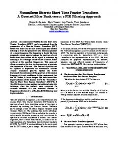
Figure 1: Simpli ed block diagram for the forward NMCLT. After a rst MCLT stage producing complex coe�cients in X, two sets of length-K MCLTs are applied separately to the last Kr samples of the real and imaginary parts of X. De ne Ta = [C1 j C2CQ + j C2SQ] and Tb = [S1 j S2CQ ; j S2 SQ] as the two forward NMCLT transform matrices. Then, the forward NMCLT transform is computed by Wa = TTa x; Wb = TTb x: (8) The steps above are depicted in Fig. 1. An example of NMCLT basis functions Ta (n; k) and Tb(n; k) is shown in Fig. 2. As expected, the responses for Ta and Tb are quite similar. Each of them is a linear combination of basis functions in C2 or S2 , with weights coming from CQ and SQ. In other words, the NMCLT basis functions are generated by combining MCLT subbands via shorter size MCLTs, as shown in Fig. 1. We see from (6){(8) that the amount of oversampling in the NMCLT is larger than 2� (as in the MCLT). This is because the rst N elements of Wa and Wb are real, whereas their last Kr elements are complex. Thus, there are more options for NMCLT reconstruction than for MCLT reconstruction. We also see from Fig. 2 that there are still time-domain aliasing terms in the NMCLT basis functions (in fact, a bit more aliasing than in the NMLBT construction in [5]). However, by combining the basis functions of Ta and Tb as discussed below, the aliasing terms in the NMCLT basis functions can be e�ectively eliminated. Let W = Wa + j Wb and T = Ta + j Tb. Then, we see from (6) and (7) that W = UT X and from (8) that W = TT x, with T = [C1 + j S1 j (C2CQ + S2SQ)+ j (C2SQ ; S2 CQ)]. The aliasing terms in C2CQ and S2 SQ have opposite signs, while those in C2SQ and S2CQ have the same sign. In other words, the aliasing terms in RefTag and ImfTbg have opposite signs, 5
NMCLT impulse responses for T and T a
b
0.2 0 −0.2 0.2 0 −0.2 0.2 0 −0.2 0.2 0 −0.2 0
64
128
192
256
Figure 2: The NMCLT basis functions Ta(n; k) and Tb (n; k) for 21 � k � 24, with M = 128, N = 16, and K = 4. Their real parts are plotted in solid lines, and the imaginary parts of Ta and Tb are plotted in dashed and dotted lines, respectively. while those in ImfTag and RefTbg have the same sign. Therefore, all time-domain aliasing terms are cancelled. An example showing the better time-domain concentration of the basis functions in the combined transform matrix T is shown in Figs. 3 and 4. We see from Fig. 4 that these new basis functions generated by the second stage have very good frequency domain characteristics; for each new set of K subbands, their passbands correspond to the sum of the K original MCLT subbands, without sacri cing stoppband performance. An inverse NMCLT transform can be computed by essentially reversing the steps in ^ a and W ^ b the processed versions of the NMCLT transform coe�cients, Fig. 1. If we call W we can apply the inverse steps corresponding to second stage in Fig. 1 to obtain X^ , the ^ a (0); :::; W ^ a(N ; 1)]T + j [W ^ b(0); :::; W ^ b(N ; processed version of X^ . Note that X^ 1 = [W 1)]T . The reconstruction formula for X^ 2 is not unique. Based on the fact that the aliasing terms in RefTag and ImfTbg have opposite signs, we choose to compute RefX^ 2g from ^ a (N ); :::; W ^ a(M ; 1)]T g via the inverse modulated lapped sine transform and ImfX^ 2g Imf[W ^ b(N ); :::; W ^ b(M ; 1)]T g via the inverse MLT. Finally, we generate the timefrom Ref[W domain reconstructed signal x^(n) by the MCLT inversion formula x^ = RefPsX^ g. ^ b(k)g and ImfW ^ b(k)g for N � k � Assuming equal quantization error levels in RefW M ; 1, this choice of the NMCLT reconstruction formula guarantees that, after the cancellation of aliasing terms, the time-domain quantization error in x^(n) will be a linear combination of basis functions in T with almost ideal time localizations. This feature is very attractive in applications like compression and denoising, since the modi cation of high-frequency sub6
MCLT impulse responses for P
a
0.2 0 −0.2 0.2 0 −0.2 0.2 0 −0.2 0.2 0 −0.2 0
64
128
192
256
NMCLT impulse responses for T= T +j T a
b
0.5 0 −0.5 0.5 0 −0.5 0.5 0 −0.5 0.5 0 −0.5
0
64
128
192
256
Figure 3: Time- domain responses of the original MCLT subbands Pa(n; k) (top) and the corresponding new NMCLT subbands T (n; k) (bottom) for 21 � k � 24, with M = 128, N = 16, and K = 4. bands will generate much shorter ringing, and therefore fewer reconstruction artifacts. For compression applications, the oversampling of the NMCLT is an issue; however, by appropriately taking into account the correlations among the NMCLT basis functions, we believe that rate-distortion performance of the NMCLT can be made very close to that of the MLT. This is currently a topic under investigation.
4 Conclusion We have introduced the NMCLT as a new nonuniform oversampled lter bank design, by extending the MCLT with a second stage of shorter MCLTs applied to the high-frequency 7
MCLT frequency responses for Pa 0
gain, dB
−20
−40
−60
−80 0.02
0.04
0.06 0.08 0.1 normalized frequency
0.12
0.14
NMCLT frequency responses for T= Ta+j Tb 0
gain, dB
−20
−40
−60
−80 0.02
0.04
0.06 0.08 0.1 normalized frequency
0.12
0.14
Figure 4: Frequency-domain responses of the original MCLT subbands Pa (n; k) (top) and the corresponding new NMCLT subbands T (n; k) (bottom) for 21 � k � 24, with M = 128, N = 16, and K = 4. subbands in a particular way. The resulting NMCLT has excellent time- and frequencydomain localization. Adaptive nonuniform subband decompositions can be easily generated by varying N on a frame-by-frame basis, which in many applications may be a better alternative than window-length switching. The NMCLT is ideally suited for processing wideband signals such as audio, in applications such as noise reduction and watermarking, with reduced time-spreading artifacts.
8
References [1] H. S. Malvar, Signal Processing with Lapped Transforms. Boston, MA: Artech House, 1992. [2] P. P. Vaidyanathan, Multirate Systems and Filter Banks. Englewood Cli�s, NJ: Prentice Hall, 1993. [3] S. Shlien, \The modulated lapped transform, its time-varying forms, and applications to audio coding," IEEE Trans. Speech Audio Processing, vol. 5, pp. 359{366, July 1997. [4] D. Sinha and A. Tew k, \Low bit rate transparent audio compression using adapted wavelets," IEEE Trans. Signal Processing, vol. 41, pp. 3463{3479, December 1993. [5] H. S. Malvar, \Biorthogonal and nonuniform lapped transforms for transform coding with reduced blocking and ringing artifacts," IEEE Trans. Signal Processing, vol. 46, pp. 1043{ 1053, April 1998. [6] H. S. Malvar, \Enhancing the performance of subband audio coders for speech signals," Proc. ISCAS'98, pp. 98{101, Monterey, CA, June 1998. [7] M. Purat and P. Noll, \Audio coding with a dynamic wavelet packet decomposition based on frequency-varying modulated lapped transforms," Proc. ICASSP'96, pp. 1021{1024, Atlanta, GA, May 1996. [8] R. L. de Queiroz, \Uniform lter banks with nonuniform bands: post-processing design," Proc. ICASSP'98, pp. 1341{1344, Seattle, WA, May 1998. [9] H. S. Malvar, \A modulated complex lapped transform and its applications to audio processing," Proc. ICASSP'99, pp. 1421{1424, Phoenix, AZ, March 1999 (a new version with typos corrected is available at http://research.microsoft.com/~malvar/papers/icassp99.pdf).
9