specific CASE tool has been developed for supporting MASs design and automatic ... Moreover, agent based platforms can offer a good way for solving complex ...
A Notation for Modeling Jason-like BDI Agents Massimo Cossentino∗ , Carmelo Lodato∗ , Antonio Chella† , Salvatore Lopes∗ , Patrizia Ribino∗ and Valeria Seidita† ∗ Istituto di Reti e Calcolo ad Alte Prestazioni Consiglio Nazionale delle Ricerche Palermo, Italy Email: {cossentino,c.lodato,lopes,ribino}@pa.icar.cnr.it † Dip. di Ingegneria Chimica Gestionale Informatica Meccanica, University of Palermo Palermo, Italy Email: {antonio.chella, valeria.seidita}@unipa.it
Abstract—The design and development of a large Multi Agent System (MAS) is a complex and difficult activity where a proper modeling notation may offer a significant contribution to the formulation of the best solution. The support provided by a specific CASE tool can significantly contribute to make the chosen approach technically valid and it is also a fundamental element of a feasible development strategy. The present work reports a UML profile and the related graphical notation for describing a MAS based on the Jason metamodel. Moreover a specific CASE tool has been developed for supporting MASs design and automatic code generation. The proposed notation is shown in details using a classical example from the Jason tutorial (domestic robot). Keywords-Jason; Multi-agent system; CASE tool
I. I NTRODUCTION Many fields of research, such as economics, biology, engineering, imply the study of highly complex scenarios in dynamic environments. In order to approach such difficult problems, open and/or distributed systems are widely employed because they can have the capability of reacting in a quasi-real time to changes occurring in the environment. Moreover, agent based platforms can offer a good way for solving complex problems because of their intrinsic nature. The agent approach is very useful to both the design and implementation phases [1][2]. Among the general purpose platforms for developing MAS (Multi- Agent System) application, JADE (Java Agent DEvelopment Framework) [3] is one of most used. Other platforms as INGENIAS [4], JACK [5], Practionist [6] and Jason [7] adopt the BDI (Belief - Desire - Intention) paradigm. In the BDI model, agents continually monitor their environments and act to change them, based on the three mental attitudes of belief, desire and intention. Jason is a Java-based interpreter supporting an extended version of AgentSpeak, a Prolog-like logic programming language and it offers relevant utilities for the implementation of MASs. Despite the relevant number of agent oriented methodologies that can be found in literature, only few of them cover the entire process life-cycle from analysis to implementation.
Very few are aided by tools and even less use a specific notation for managing all the concepts a MAS deals with. In the case of BDI agents, concepts like agent, role, goal, communication, plan, belief, desire, and intention have to be defined during the design methodology activities. A proper notation would allow a more efficient way for designing the system and it would better fill the gap between the design process and the used platform. In this paper we present a notation for modeling Jasonbased MAS and a preliminary version of a CASE tool, named JT (Jason Tool). The advantages of graphically representing MAS are evident: first of all, graphical notations are more readable and understandable at a glance than any coding language, secondly it is usually easier to explain a graphical model to stakeholders involved in the design (that are not technical designers) than read the application code with them. The notation here presented is based on a UML 2.3 profile and it allows to draw the following diagrams: the Goal Structural Description (GSD) expresses the structural decomposition of the system goals, the Multi Agent Structural Description (MASD) describes the system in terms of agents, their plans and interactions, the Multi Agent Functional Description (MAFD) depicts the system dynamical behaviour, the Single Agent Structural Description (SASD) highlights the internal structure of each agent. These diagrams are supported by JT that permits the MAS design and its implementation for the Jason platform. JT has been implemented by using a well known tool, Metaedit+ by Metacase [8][9]. It offers a valid environment for domain specific modeling and it provides means for creating an adhoc modeling language with concepts and rules coming from the problem domain. The present work is part of a more complex and complete one. We are working on the definition of a methodological approach for the design of BDI MAS where the proposed diagrams represent the outcome of the methodology activities. In this paper we want only to show the adopted notation for representing not only common agent concepts but principally specific Jason elements. We started from the bottom with the
precise intent of giving meaning to the coding concepts in the same way the creators of UML do [15]; only after this step we can go on with the definition of the methodology phases. The remainder of the paper is organized as follows. In section II the Jason platform and Metaedit+ are introduced. In section III we explain the proposed tool with its diagrams and notation by using an example inspired by a Jason tutorial. Finally some discussions and conclusions are drawn in section IV. II. BACKGROUND AND M OTIVATION During the design and the implementation of a multiagent software system, it is useful to follow specific design activities ruled by a methodology that leads the designer from the system analysis to its implementation with a specific programming language. In fact, the use of a correct methodological approach results in a valuable software product also reducing development time and costs. The adoption of a CASE tool further improves on these advantages. A relevant gap may exist between the design and the implementation platform. This has been historically relevant in the field of MAS development because most agent platforms are based on object oriented concepts and they support agent oriented abstraction with great limits. In the case of BDI multi-agent systems, AgentSpeak and its extension Jason present valuable features for applying logic programming to BDI agents. Jason natively allows to manage concepts like goal, belief, event and all the others a BDI context would imply. Several agent oriented methodologies for developing BDI agents exist. Some of the most known are: MASCommonKADS [10], MASE [11], Prometheus [12] and INGENIAS [13]. Each of these methodologies produces models using a specific modelling language. MAS-CommonKADS [10] defines a set of models: Agent, Task, Expertise, Coordination, Communication, Organization and Design. It extends and integrates object-oriented and knowledge engineering techniques. MAS-CommonKADS is a complete methodology from analysis to implementation. The Organizational model deals with elements such as mental state, hence goals, plans and beliefs and external interface, hence sensors, actuators and services. The notation used by MAS-CommonKADS is quite similar to the UML one and no specific notation has been defined for representing the peculiar concepts of BDI agents. Besides there is a poor support from dedicated CASE tools. MASE [11] provides two main phases, the analysis and the design and it mainly creates models and guidance for developing a detailed design. During the analysis phase, a set of goals is identified and then used for creating use case and sequence diagrams for representing the behaviour of the system. In the following phases, roles and tasks are
designed and finally transformed in the implementationlevel agents and their conversations. AgentTool provides a development environment for MASE and it includes semiautomatic transformation of models. Prometheus [12] supports the design of BDI agents based on goals and plans. The methodology covers the design phases from system specification to detailed design where the system dynamics is specified in terms of interaction protocols and the design of agents in terms of capabilities. The methodology also allows to design elements such as message, plan, action and perception. Prometheus can be supported by two tools, Prometheus Design Tool (PDT) and JACK Development Environment (JDE). PDT [14] is based on a specific notation and allows the designer to draw the Prometheus work products and to check for inconsistences. JACK is a platform for building, integrating and running BDI multi-agent system. INGENIAS defines a notation for the specification of MAS, extending UML with agent related concepts such as agent, organization, role, goals and tasks. It also defines activities for the identification and the specification of MAS components in analysis and design. INGENIAS links concepts of different diagrams and allows mutual references. Its metamodel has been elaborated attending to current research results in different areas like coordination, reasoning, and workflow management. Moreover, the INGENIAS Development Kit (IDK), coded in the Java language, provides a framework for the implementation of modules, for verification and code generation [4]. At the best of our knowledge, only few methodologies are supported by CASE tools and none is specific for designing Jason agents. What we aim to do is to create a comprehensive methodological approach for developing cognitive BDI agent by joining the strength of Jason agents and the availability of a tool for the design and the automatic generation of Jason code. The work we propose in this paper is the first step towards our main aim and it deals with the definition of a UML extended notation for modeling Jason agents. Our research and its outcome are based on the assumption, taken by the MDE paradigm [16], that developing a software system is nothing more than transforming models along the methodological activities. Drawing models, hence all the diagrams they include, is ruled by the chosen notational syntax and by the system metamodel constructs each activity is devoted to design. The tool we developed is an instance of a meta-Case tool (Metaedit+); we decided to use Metaedit+ for its rapid prototyping capability of the solution. In fact, it offers the possibility of creating a graphical environment for the newly created notation and of automatically producing the related code. In the next subsection we give an overview on Jason, its metamodel, and on Metaedit+.
A. JASON Jason is a Java-based interpreter for an extended version of AgentSpeak [17][18], a Prolog-like logic programming language. The most interesting features of AgentSpeak is that it is based on a the belief-desire-intention (BDI) model [19]. In this model, agents are continually observing their environment. If some change happens agents produce a reaction that depends on the three mental attitudes of belief, desire and intention. Beliefs are information the agent has about the world (i.e. itself, others agents and the environment), which could also be out of date or inaccurate. Desires represent all possible states of affairs that an agent would achieve. A desire is what drives the agents actions. So it is possible for a rational agent to have desires that are mutually incompatible each other. Thus, Desires represent possible options for an agent. Intentions are the states of affairs that the agent has decided to work towards. An agent looks at its options and chooses between them. Options selected in this way become intentions. The behavior of agents in Jason is defined by means of a set of plans performed with the aim to fulfil goals. Practically, agents sense the environment and react to the perceptions coming from it. Perceptions are generated from changes happened in the environment where agents live. Such perceptions have practical influence on agents beliefs and consequently on the commitment to the achievement of agents goals. From a practical point of view, Agents respond to changes by selecting plans from the own plan repository for each change of beliefs and then by instantiating one of these plans as an intention. These intentions can be composed of actions, goals and plans to be achieved. A plan in AgentSpeak is composed of three main elements organized in the following form: +triggeringEvent : context < −body The triggeringEvent is something (changes in agents belief, goals to achieve) representing the situation in which the agent should execute a suitable action. Since there can be several plans triggered by the same event, the context can be used for specifying which among all the eligible plans should be performed. The body can be considered the consequent of the event linked to the context.Within the body commonly the actions that an agent must perform to fulfill its own goals are defined. The fundamental elements appearing in the Jason programming of an Agent are: Beliefs: a set of predicates representing the initial agent knowledge of its environment. Rules: a set of logic expression composed by predicates or mathematical equations. Plans: sets of actions or and subgoal to be performed in order to fulfil the current goal.
Belief updates
Goal
pursues
Context
Trigger Event
Rule satisfies
Message updates
Agent
Plan executes
Event
communicates reacts
Action causes
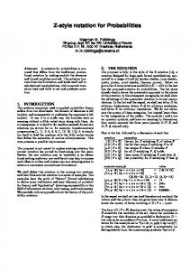
Figure 1.
The Jason Metamodel
Figure 1 shows an excerpt of the Jason metamodel deduced from [20]; this metamodel may be useful for the reader to understand the choices made about the notational elements (see later in section III). It contains all the elements the designer has to deal with and to report in, at least, one diagram of the produced model. The Agent has Beliefs and pursues Goals. It reacts to Events executing Plans in order to change the world and to purse its goals. Beliefs represent the information an agent owns. Beliefs added or removed to the belief base during the execution of a plan are known as Mental Notes. Goals represent the situation (the state) the agent wants to reach. They can be of two types: achievement (goal to do) and test (goal to know). Events happen as a consequence to changes in the agent beliefs or goals. There are six types of events: belief addition and deletion, achievement goal addition and deletion, test goal addition and deletion. Actions are simple tasks that an agent can perform inside a Plan. Jason platform provide two kinds of Actions: the Internal Actions (that does not produce changes in the environment) and External Actions (that change the environment). Plans represent the agent know-how. A Plan contains a Trigger Event defining in which circumstances it should be considered.It may contain Actions, Goals and Mental Notes. The related Context represents the conditions under which the plan can be executed and it may be composed of Beliefs or logical expressions. Every element in the metamodel has to be instantiated in at least one artefact during the development of the Jason multi-agent system. In the next subsection we give an overview on the diagrams created in order to design the multi-agent system. They provide a structural and a behavioral view of the single agent involved in the system and of the society of agents.
B. Metaedit+ Metaedit+, developed by Metacase [8], is at the same time a CASE tool and a meta-CASE tool. Hence using Metaedit+ gives the possibility of creating and specifying modelling languages with specific syntax and semantic for each element of the notation. This fact is allowed by the three layered structure of Metaedit+ that basing on the GOPPRR (Graph, Object, Property, Port, Relationship and Role) metamodeling language establish concepts and rules for creating metamodels and as a consequence modeling languages with the related graphical editor. Moreover Metaedit+ offers the possibility of using and creating what is called report. The report is a small program defined and working on every diagram that may produce document generation in html format or others and the generation of code skeleton in various programming languages (Java, C, C++,. . . ). Besides Metaedit+ is provided with an optimum support for the UML modeling language. In a nutshell, we exploited these two main Metaedit+’s features for defining our UML profile for modeling Jason agent with its related graphical editor and for automatically generating code skeleton. The latter is not in the focus of this paper. III. T HE P ROPOSED N OTATION In order to illustrate the proposed notation and how it is used for designing a Jason MAS, we use throughout the paper an example provided by the Jason tutorial [20], the Domestic Robot example. In this case study, a robot is employed in order to provide its owner with the beer he wants to drink. In this section we present our notation by means of four specific diagrams showing the MAS solution adopted for the domestic robot problem. The diagrams we show in the next subsections are supported by our Jason Tool and are the outcome of the design activities we are working on and that, here, we only hint at. The four diagrams cover both the analysis and the design of the solution. As regard the requirements analysis, we think a fundamental diagram would be the Goal Structural Description one. This latter decomposes the main system goals in sub-goals. It is largely inspired by the Tropos approach [21] and it can be refined using techniques like the means-end analysis.As regard the design phase, we refer to two different levels of abstraction. First of all, the social (multi-agent) level is presented. This level deals with the collaborative, social solution to the problem. The diagrams represent all the agents involved in collaborations aiming to satisfy the requirements. The next level, the single-agent one, deals with the inner perspective of the agent design. This diagram represents all the elements that constitute the detailed agent design and that are necessary to code each single agent. Both the levels contain a structural and a
behavioral diagram although this latter is not significant (in our example) at the single-agent level and will be omitted.
Figure 2. The Goal Structural Description diagram for the domestic robot example
A. The Goal Structural Description Diagram This diagram presents a static decomposition of the problem goals. It is a mean for analyzing the problem and sketching a solution in terms of goals and sub-goals. From this point of view, this is not dissimilar from the diagram we already presented in the notation proposed for modeling organizations of agents (based on J-Moise) [22]. The GSD for the domestic robot problem is reported in Figure 2. This diagram shows that the main goal is that someone wants to drink a beer(goal drink(beer)). To do this someone must get a beer (goal get(beer)). A beer can be obtained only going to the fridge(goal go to(fridge)) and taking a bottle of beer from the fridge (goal take(beer)). If the fridge is empty then the goal take(beer) is subordinated to the goal order(beer). In addition, the goal get(beer) contributes negatively to the prevention of drunkenness that represents a soft goal (depicted by means of a cloud) for the system. Different design choices may arise from this scheme in terms of roles and operative plans. The scenario adopted in the Jason tutorial for the reported example considers a domestic robot whose main goal is serving beers to its owner. In order to pursue this goal, it must receive beer requests from its owner, then go to the fridge, take out a bottle of beer, and bring it to the owner. Moreover, the robot must be aware of the amount of beers available in the fridge and if the case, it should be able to order more beers using the supermarket home delivery service. Some rules are hard-wired into the robot by the Department of Health, in the particular case a rule defines the limit of daily beer
consumption. We are here accepting the solution proposed in the Jason tutorial in order to enable an easier understanding of our proposal to the reader. B. The Multi-Agent Level Diagrams At the multi-agent level, two diagrams have been conceived in order to design a MAS solution for a given problem. In the specific case, we have introduced the MultiAgent Structural Description (MASD) diagram in order to model the system in terms of agents and their relations and the Multi-Agent Functional Description (MAFD) diagram in order to describe the dynamical behavior of the system.
Figure 3. Multi-Agent Structural Description diagram designed for the domestic robot example
Multi-Agent Structural Description Diagram. A MASD is an extended UML class diagram. Figure 3 shows the notation elements allowed in a MASD diagram applied to the domestic robot example. The icon representing a man with a tie is the agent symbol in our notation. Moreover, according to the Jason viewpoint, the agents interact by means of communications. These relations are represented as arrows from the sender to the receiver agent labelled with the intention of the sender (the performative). From the structural viewpoint, the MAS to be developed for solving the domestic robot problem is composed of three agents: the owner, the robot and the supermarket. In a MASD diagram, the body of an agent is usually composed of four fields containing its initial beliefs (a priori knowledge about the world), initial goals(goals the agents will attempt to achieve from the beginning), rules (beliefs coming from a logical consequence of other beliefs) and plans (the agent’s know-how). Thus, according to the specifications of the domestic robot problem, only the owner agent has an initial goal (get(beer)) because this agent is the only one that can start the activities of whole system. In turn, the robot has two initial beliefs concerning the availability of beers in the fridge and the legal limit of beers the owner can drink. The
rule too much allows the robot to understand if its owner has exceeded the limit. The supermarket agent initially knows the last order ID of the robot. Each agent according to its task is endowed with some plans that allow it to fulfil its goals. In a MASD diagram a plan is defined using the following syntax: operatorf unctor([terms]) : context where the operator can be a goal operator (!, ?, !!) or a belief operator (+, -, -+); functor([terms]) is the trigger event of the plan and it is the formal representation of a Jason beliefs or goals; the context defines the conditions in which the plan can be applicable. It is composed of logical expressions combined with the operators not (negation), & (conjunction) and — (disjunction). Besides, some communications among agents are used in order to solve the domestic robot problem. For example the owner agent has to make a request to its domestic robot in order to get a beer. In the diagram of Figure 3, this communication is represented by means of an arrow between the owner and the robot labelled with an achieve performative. It means that the owner is delegating a goal to the robot. Instead, the communication between the supermarket and the robot contains a tell performative that means the supermarket wants only to inform that the beers have been delivered. Multi-Agent Functional Description Diagram. A MAFD diagram is an extended UML activity diagram. It provides a detailed description of the behavior of a MAS highlighting the sequence of activities performed by the agents. More in details it represents plans, message exchanging and action executions. Figure 4 shows the complete MAFD diagram for the domestic robot example. This diagram reports all the possible plans for each agent, the actions for each plan, the exchanged messages and all the possible perceptions. In the specific case, the agent owner triggers the behavior of the MAS activating the plan related to the fulfillment of the initial goal get(beer). This plan is composed of a send action that allows the owner to request the robot to bring a beer. The message performative is achieve, and when the robot receives this message it activates the related plan (has(owner,beer)). When all the necessary actions to bring a beer are accomplished, the robot executes the action hand in(beer) that causes to include the belief has(owner,beer) in the belief base of the owner agent. The Figure 4 also shows the notation elements allowed in the MAFD diagram.The main element of the MAFD diagram is the Jason plan. This is a specialization of a UML activity. Thus, as usual, it is depicted with a rounded rectangle and its invocation with a reversed pitchfork (see also UML 2.3 [23], pag. 359). In this perspective, each plan may contain other plans and/or simple actions.
In the MAFD diagram, six types of actions may be represented: external actions (actions that modify the environment); internal actions (actions that do not change environment); send actions (a particular internal action that activates a communication among agents); finally we have introduced three dummy actions, beliefs deletion, belief addition (representing the agent mental notes) and test action (representing the Jason test goal action used by an agent to retrieve information during plan execution). These last actions are represented by means of an ellipse with a stereotype indicating the type of dummy action. In addition, a plan can be parametrized using an input pin according to the specification of UML 2.3 (see [23], pag. 415). Pins are used to specify parameters passed to plans. For instance, plan at(robot, P) has the pin P=fridge when it is invoked the first time by the robot under the context available(beer,fridge)¬ too much(beer). A similar notation has been already proposed in [24] but without any specific reference to the Jason language. Besides, in the MAFD diagram it is possible to represent two kinds of resources by means of a UML object node:message and belief. Messages can be sent executing the specific internal action(send). For this reasons, in a MAFD diagram each send action is linked to the message. These messages contain a performative (for example: tell, achieve, askone etc.) and the content. In turn, beliefs may be generated by external actions and perceived by agents (see, for instance, the belief has(owner,beer) generated by the external action hand in(beer) in the biggest plan of robot in Figure 4 and perceived by the owner agent). This diagram is quite complex, its difficulty is comparable to that of the coding phase of a Jason agent. However it is to be noted that the MAFD diagram has been conceived for substituting the code; the work is done only once during the related modeling activity where one can use higher level concepts having a better overall view of the MAS. Obviously this diagram could be partly developed and after the involved elements can be completed during the coding phase, the design is free to act as he prefers; what we want to underline is that the complexity of this diagram does not increase the complexity of developing a Jason MAS. C. The Single-Agent Level Diagram At the single-agent level, one diagram for each agent defined in the MASD diagram is designed. In our notation, we have introduced the Single Agent Structural Description (SASD) diagram in order to highlight the internal structure of an agent. As it can be seen by the Jason metamodel (Figure 1), an agent is usually composed of plans, rules, goals and beliefs. A SASD diagram provides a description of the agent elements that is more detailed than the MASD diagram one. In a SASD diagram, particular attention is paid to plans. A plan contains a set of tools the agent may apply to change the
world and achieve its goals. Usually, carrying out a complex plan requires not only simple actions to be executed but also intermediate goals to be reached. Thus, from the structural perspective a plan may be composed of external and internal actions, achievement and test goals and mental notes. Figure 5 shows the SASD designed for the robot agent of the domestic robot example. On the left top corner, the initial beliefs and the rules of the robot agent are reported. The remaining part of the diagram explicits the plans the agent is composed of. For instance, it is possible to note that, in order to satisfy the has(owner,beer) goal the robot is endowed with three plans applicable in different circumstances. The first plan on the left of the diagram, is applicable only if the agent robot knows there are beers available in the fridge and the owner has not exceeded the legal limit of beers for the day. This plan contains several simple actions (open(fridge), get(beer)) with an obvious meaning and two achievement goals that the robot must fulfil in order to reach the fridge and the owner respectively. We omit the description of the remaining part of the diagram for space concerns. IV. C ONCLUSIONS AND F UTURE W ORKS This paper deals with the creation of a notation for developing Jason multi-agent systems. Jason is a platform allowing the implementation of BDI agents and it provides a programming language for cognitive agents by managing concepts like goal, plan, belief, event and so on. Our aim is to create an agent oriented design process for developing such a kind of agent systems. This paper represents a first step towards pursuing this objective; we decided to join the strength of Jason to that of a CASE tool for supporting design. The methodological approach and all its activities for doing that are out of the scope of this paper but they were at the basis of our work. First of all we deduced the Jason metamodel that provided us an overview of the elements that must be designed. This was a consequence of the fact that we exploit the MDE philosophy about metamodeling: every model produced by a design process is an instance of a metamodel containing all the constructs to be managed during design. The notation we created is composed of all the elements that allow us to instantiate four different diagrams. The diagrams we propose are: the Goal Structural Description (GSD) diagram that expresses the structural decomposition of the system goals, the Multi Agent Structural Description (MASD) diagram describing the system in terms of agents, their plans and interactions, the Multi Agent Functional Description (MAFD) diagram depicting the system dynamical behaviour, the Single Agent Structural Description (SASD) diagram highlighting the internal structure of each agent. The notation has been created as a UML 2.3 profile and it can be used through the tool we defined by using Metaedit+. This tool is a good prototype that allowed us to experiment our notation in different case studies but it does not offer
Figure 4.
Multi-Agent Functional Description diagram designed for the domestic robot example
any specific support for methodological issues like sequence of design activities, coherence checks and so on. As a future work, we plan to create an Eclipse plug-in for supporting all the activities of the process devoted to design Jason MAS by exploiting our notation. Acknowledgment: This research has been partially supported by the EU project FP7-Humanobs and by the FRASI project managed by MIUR (D.M. n593). R EFERENCES [1] M. Wooldridge and N. Jennings, “Intelligent Agents: Theory and Practice,” The Knowledge Engineering Review, vol. 10, no. 2, pp. 115–152, 1995. [2] M. J. Wooldridge, Introduction to Multiagent Systems. John Wiley & Sons, Inc. New York, NY, USA, 2001.
[3] F. Bellifemine, A. Poggi, and G. Rimassa, “Jade - a fipa2000 compliant agent development environment,” in Agents Fifth International Conference on Autonomous Agents (Agents 2001), Montreal, Canada, 2001. [4] INGENIAS, “Home page,” http://grasia.fdi.ucm.es/ingenias/metamodel/. [5] M. Winikoff, “JackTM intelligent agents: An industrial strength platform,” Multi-Agent Programming, pp. 175–193, 2005. [6] V. Morreale, S. Bonura, G. Francaviglia, F. Centineo, M. Puccio, and M. Cossentino, “Developing intentional systems with the practionist framework,” in Industrial Informatics, 2007 5th IEEE International Conference on, vol. 2. IEEE, 2007, pp. 633–638. [7] R. H. Bordini, J. F. H¨ubner, and M. J. Wooldridge, Programming multi-agent systems in AgentSpeak using Jason. WileyInterscience, 2007.
Figure 5.
Single-Agent Structural Description diagram for the robot agent of the domestic robot example
[8] J.-P. Tolvanen and M. Rossi, “Metaedit+: defining and using domain-specific modeling languages and code generators,” in OOPSLA ’03: Companion of the 18th annual ACM SIGPLAN conference on Object-oriented programming, systems, languages, and applications. New York, NY, USA: ACM Press, 2003, pp. 92–93.
[16] D. C. Schmidt, “Model-driven engineering,” Computer, vol. 39, no. 2, pp. 25–31, Feb. 2006.
[9] I. H. and L. D. A., “Case environments and metacase tools,” 1997.
[18] M. d’Inverno and M. Luck, “Engineering agentspeak (l): A formal computational model,” Journal of Logic and Computation, vol. 8, no. 3, p. 233, 1998.
[10] C. Iglesias, M. Garijo, J. Gonz´alez, and J. Velasco, “Analysis and design of multiagent systems using mas-commonkads,” Intelligent Agents IV Agent Theories, Architectures, and Languages, pp. 313–327, 1998. [11] S. A. DeLoach and M. Kumar, “Multi-agent systems engineering: An overview and case study,” ch. XI, pp. 317–340. [12] L. Padgham and M. Winikof, “Prometheus: A methodology for developing intelligent agents,” in Agent-Oriented Software Engineering III, ser. LNCS, F. Giunchiglia, J. Odell, and G. Weiss, Eds. Springer, 2003, vol. 2585, pp. 174–185, 3rd International Workshop (AOSE 2002), Bologna, Italy, 15 Jul. 2002. Revised Papers and Invited Contributions.
[17] A. Rao, “AgentSpeak (L): BDI agents speak out in a logical computable language,” Agents Breaking Away, pp. 42–55, 1996.
[19] A. Rao and M. Georgeff, “Bdi agents: From theory to practice,” in Proceedings of the first international conference on multi-agent systems (ICMAS-95). San Francisco, 1995, pp. 312–319. [20] R. Bordini and J. H¨ubner, “Bdi agent programming in agentspeak using jason (tutorial paper),” Computational logic in multi-agent systems, pp. 143–164, 2006. [21] P. Bresciani, A. Perini, P. Giorgini, F. Giunchiglia, and J. Mylopoulos, “Tropos: An agent-oriented software development methodology,” Autonomous Agents and Multi-Agent Systems, vol. 8, no. 3, pp. 203–236, 2004.
[13] J. Pav`on, J. J. G`omez-Sanz, and R. Fuentes, “The INGENIAS methodology and tools,” in Agent Oriented Methodologies. Idea Group Publishing, 2005, ch. IX, pp. 236–276.
[22] “Designing mas organizations with the support of a uml case tool,” in Proceedings of the Fourth European Workshop on Multi-Agent Systems (EUMAS’11), 2011.
[14] L. Padgham and M. Winikoff, “Prometheus: A pragmatic methodology for engineering intelligent agents,” in Proceedings of the OOPSLA 2002 Workshop on Agent-Oriented Methodologies. Citeseer, 2002, pp. 97–108.
[23] UML, “Object Management Group,” OMG UML Specification v. 2.3, 05-05- 2010.
[15] J. Rumbaugh, “Notation notes: Principles for choosing notation.” Journal of Object-Oriented Programming, vol. 9, no. 2, pp. 11–14, Mat 1996.
[24] V. da Silva, R. Noya, and C. de Lucena, “Using the uml 2.0 activity diagram to model agent plans and actions,” in Proceedings of the fourth international joint conference on Autonomous agents and multiagent systems, 2005.