A Novel Approach for FFT Data Reordering. Marwan A. Jaber and Daniel Massicotte. Université du Québec à Trois-Rivières, Electrical and Computer ...
A Novel Approach for FFT Data Reordering Marwan A. Jaber and Daniel Massicotte Université du Québec à Trois-Rivières, Electrical and Computer Engineering Department Laboratory of Signal and System Integration {marwan.jaber, daniel.massicotte}@uqtr.ca Abstract: The Fast Fourier Transform (FFT) is a key role in signal processing applications that is useful for the frequency domain analysis of signals. The FFT computation requires an indexing scheme at each stage to address input/output data and coefficient multipliers properly. Most of these indexing schemes are based on bit-reversal techniques that are boosted by a look-up table requiring extra memory storage. This paper describes a novel data reordering technique based on the vector calculation of size r. FFTs are considered in-place (or in situ) algorithms that transform a data structure by using a constant amount of memory storage. We demonstrate that our proposed method reduces memory usage by eliminating the look-up table traditionally employed in the computation of bit-reversal indexes. 1. INTRODUCTION The FFT algorithm is especially memory access and storage intensive, where the communication burden of an algorithm is a measure of the amount of data (written and read) that must be moved to and from memory as well as between computing elements. Therefore, FFTs are typically used to input large amounts of data, perform mathematical transformation on that data, and then output the resulting data all at very high rates. In a real time system, data flow must be understood and controlled in order to achieve the high performance of a future wireless communication system based on orthogonal frequency division multiplex wireless communication (OFDM) wherein the FFT is a major key operator [1]. Since the butterfly computation consists of a simple multiplication of the input data with an appropriate coefficient multiplier, the idea arises to have simple address generators (AG) compute such address sequences from a small parameter set that describes the address pattern. Because the butterfly’s CPU should only be used to compute mathematical transformation, it is preferable for dataflow to be controlled by an independent device; if not, the system may incur performance degradation. Such peripheral devices, which can control data transfers between an input/output subsystem and a memory subsystem in the same manner as a processor, reduce computational processor interrupt latencies and leave valuable DSP cycles free for other tasks, leading to improved performance [2]. Thus, given that dataflow control is a major concern in the FFT process, inadequate AG burden the memory interface with additional load and slow down computations [3]. One “rediscovery” of the FFT, that of Danielson and Lanczos in 1942, provides one of the clearest derivations of algorithms [4] and [5]. Danielson and Lanczos showed that a discrete Fourier transform could be written as the sum of two discrete Fourier transforms, each of length N/2. In the mid-1960s, J.W. Cooley and J.W. Tukey proposed their first algorithm, known as the decimation-in-time (DIT) or Cooley-Tukey FFT algorithm, which first rearranges the input elements into bit-reverse order,
978-1-4244-5309-2/10/$26.00 ©2010 IEEE
then builds up the N-data output transform in log2N iterations; in other words, the radix-2 DIT algorithm first computes the transform of even-indexed and odd-indexed data, then combines these two results to produce the Fourier transform of the entire data sequence [6]. Since that time, several techniques have been proposed for ordering and accessing the data at each stage of the FFT; the best known reordering technique is the bit-reversal in which the data at index n are written in binary digits that are permuted in reversed order. In this paper we propose an innovative AG structure that is faster than the bit-reversal technique most frequently proposed and compared with the most recent published bit-reversal techniques. The paper is organized as follows: Section 2 gives a brief outline of the bit-reversal technique; Section 3 describes the proposed method, Section 4 provides the performance results of that method and Section 5 contains the conclusion. 2. Bit-Reversal Techniques Many FFT users prefer the natural order outputs of the computed FFT; this is why they concentrate their efforts on reducing the computational time impact in the bit-reversal stage, the first stage of the DIT process known as the bit-reversal data-shuffling technique. The DIT FFT became attractive in fixed-point implementation when Chang and Nguyen showed in [7] that the DIT process executed in fixed-point arithmetic is more accurate than the decimation-in-frequency (DIF). Furthermore, reordering the intermediate stage of the FFT algorithm is highly recommended in order to facilitate the operation on the consecutive data element required for many hardware architectures. To these ends, a number of alternative implementations have been proposed; one of these has greatly simplified the problem by adopting the out-of-place algorithm where input and output arrays are distinct. This section will therefore be devoted to reviewing the existing current architecture of the bit reversal technique needed at the first stage of the DIT process, where a number of bit-reversal algorithms [8], [9] and [10] - have been published in recent years. The vector calculation method proposed by Pei & Chang for the bitreversal technique is the “fastest known technique” and is used in our comparative study [10]. The operation count of the proposed algorithm in [8] when index calculations for each stage are excluded is N - 2 integer additions, 2( N - 2) integer increments, (1) (log 2 N ) -1 multiplications by 2, (log 2 N ) -1 divisions by 2,
plus two more divisions: N/2 and N/4. In Eq. (1), multiplications and divisions can be efficiently implemented using bit-shift operations. In addition, this algorithm will require a storage table of N/2 index numbers [8].
1615
On the other hand, the proposed method in [10] reveals a significant improvement in the operation count, which will require N shifts, N additions, an index adjustment and the use of O(N) memories. 3. Proposed Method
for p = 0,1,...., ( N / r ) − 1 and q = 0,1,...., r − 1 with T
X = ⎡⎣ X ( p ) , X ( p + N / r ) , X ( p + 2 N / r ) , …, X ( p + ( r −1) N / r ) ⎤⎦ ,
WN = diag ( wN0 , wNp , wN2 p , ⎡ wN0 ⎢ 0 ⎢ wN ⎢ 0 w Tr = ⎢ N ⎢ ⎢ ⎢ ⎢ 0 ⎢⎣ wN
n = 1,… , N , N = r S , and r and S are integers, the definition of the DFT, using the twiddle factor, w = e by the following equation N -1
∑x
X (k ) =
n=0
(n)
2π nk −j N
, is represented
wNnk , k ∈ [0, N -1]
(2)
which can be factorized as follows: N −1 r
X ( k ) = ∑ x( rn ) w
rnk N
n=0
N −1 r
+ ∑ x( rn +1) w
( rn +1) k N
n =0
N −1 r
N −1 r
+ ∑ x( rn + 2) wN( rn + 2) k n=0
,
(3)
+ ∑ x( rn + ( r −1) ) w
+
( rn + ( r −1) ) k N
n=0
where after simplification, equation (3) can be expressed as X (k ) = w
0 N
N −1 r
∑x
( rn )
n=0
nk N /r
w
+w
k N
N −1 r
N −1 r
∑x n=0
wN2 k ∑ x( rn + 2) wNnk/ r + n=0
for k = 0,1, new
axis
( rn +1)
wNnk/ r +
,
N −1 r
(4)
+ wN( r −1) k ∑ x( rn + ( r −1) ) wNnk/ r n =0
, N − 1 . To subdivide the axis k in Eq. (4) in two
p
and
q,
we
pose
k = p + qN / r
replaced by using new indices p and q X ( k ) = X ( p + q ( N / r )) . Finally, Eq. (4), can be formulated in a matrix-vector notation as
⎡ wN0 ⎢ 0 ⎢ wN ⎢ 0 ⎢ wN ⎢ ⎢ ⎢ ⎢ 0 ⎣⎢ wN
X ( p+ N / r)
wN0
X ( p+2N / r)
wN0
N /r N
w
wN2 N / r
wN2 N / r
wN4 N / r
wN(
r −1) N / r
wN(
2 r −1) N / r
T
X ( p + ( r −1) N / r ) ⎤ = ⎦ N −1 ⎡ ⎤ r 0 ⎢ ⎥ wN ∑ x( rn ) wNnp/ r ⎢ ⎥ n =0 ⎥ wN0 ⎤ ⎢ N −1 ⎥ ⎥⎢ r ( r −1) N / r ⎢ wN ⎥ wNp ∑ x( rn +1) wNnp/ r ⎥ ⎢ ⎥ n =0 2 r −1 N / r ⎥ ⎥ wN( ) ⎥ ⎢ N − 1 ⎥ r ⎥⎢ 2 p np ⎥ ⎢ wN ∑ x( rn + 2) wN / r ⎥ ⎥ n =0 ⎥⎢ ⎥ ⎥⎢ ( r −1)2 N / r ⎢ ⎥ wN ⎦⎥ ⎢ N ⎥ −1 ⎢ ( r −1) p r np ⎥ x( rn + ( r −1) ) wN / r ⎥ ∑ ⎢ wN n =0 ⎣ ⎦
(5) which can be expressed compactly as: ⎛ Nr −1 ⎜ X = Tr WN col ⎜ ∑ x( rn + q ) wNnp/ r q = 0,1, ⎜ n=0 ⎝
⎞ ⎟ , r − 1⎟ , ⎟ ⎠
(6)
wN0 N /r N
w
2N / r N
wN4 N / r
w
r −1) N / r
wN0
( r −1) N / r
2N / r N
w
wN(
⎤ ⎥ wN ⎥ 2( r −1) N / r ⎥ wN ⎥. ⎥ ⎥ ⎥ ( r −1)2 N / r ⎥ wN ⎥⎦
wN0
wN(
2 r −1) N / r
(9)
In DSP Layman language, the factorization of an FFT can be interpreted as a dataflow diagram (or Signal Flow Graph – SFG), which depicts arithmetic operations and their dependencies. When Eq. (6) is read from left to right, we obtain the decimationin- frequency algorithm; if the dataflow diagram is read from right to left, we obtain the decimation-in-time algorithm. When examining Eq. (5) or (6), one might easily conclude that it is necessary to compute the transform of r sets of data of size N/r, and then combine these r results to produce the Fourier transform of the entire data sequence. N/r vector sets of size r must be processed at every stage of the ordered-input orderedoutput (OIOO) FFT algorithm; therefore, r specific data provided by the DIT Reading Data Address Generator (RDAG) should be fed to the butterfly’s input. For this version of the FFT, the mth butterfly’s input x(m) of the pth word at the sth stage (ith iteration) is fed by the OIOO DIT RDAG ( m, p , s ) [3] as ⎛ N RDAG ( m , p , s ) = m ⎜ ( s +1) ⎝r
with
p = 0,1,...., ( N / r ) − 1 and q = 0,1,...., r − 1 . Therefore, X ( k ) is
⎡X p ⎣ ( )
(8)
and
The proposed method is based on the radix–r DFT factorization proposed in [11]-[15]. Considering a signal x( n ) with
nk N
, wN( r −1) p ) ,
(7)
⎞ ⎟+ p ⎠
r S -s
⎢ p ⎥ + ⎢ ( S - s ) ⎥ r ( S +1- s ) , ⎣r ⎦
(10)
for m = 0,1,… , r − 1 , p = 0,1,… , ( N / r ) − 1 and s = 0,1,… , S , S = log r N − 1 where x
N
represents the operation x modulo N
and ⎣⎢ x ⎦⎥ represents the integer part operator of x. When a comparison is made with the bit-reversal algorithms required to reorder input (DIT) or output (DIT) data , it is clear that for the first iteration/stage (i.e. s = 0), equation (10) will be equal to RDAG ( m, p , s ) = m ( N / r ) + p
(11)
On the other hand, (7) reveals that the transformed outputs are in a bit-reverse order. This means that the transformed outputs of each set of the input data are obtained at a stride N/r, which then means that to obtain ordered output, the lth processed butterfly’s output X(l,p,s) for the pth word at the sth stage should be stored into the memory address location given by the Writing Data Address Generator (WDAG): WDAG ( l , p , s ) = l ( N / r ) + p ,
(12)
for l= 0, 1,…, r – 1, and p= 0, 1, …, (N/r) – 1. Equation (11) represents the bit-reversal stage in the DIT process; equation (12), which is identical to equation (11), represents the bit-reversal stage required at the end of the DIF process. In an OIOO DIT FFT process, the two inputs of the
1616
butterflies' radix-2 will be labeled thus: m=0 for the first input and m=1 for the second. Consequently and according to (11), the first butterfly’s input will be driven by the data located at the memory address RDAG (0, p ,s) = p
(12)
and the second butterfly’s input will be driven by the data located at the memory address
G=
3 N + 2 log 2 N − 8 , N /2
(13)
for Rius & de Porrata-Doria [8], and G=4,
(14)
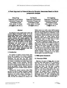
for the vector calculation method proposed by Pei & Chang [10]. Fig. 2 shows the performance gain for N = 2 S .
RDAG (1, p , s ) = ( N / r ) + p (13)
7
Fig. 1 shows the C implementation of the proposed method for the DIT process that requires only (r–1)N/r additions which can be used in an OIOO for each stage/iteration of the FFT process where In0, In1 are the butterflies’ inputs and SrcMemory refers to the Source memory from which the data are retrieved. By replacing SrcMemory in this figure by DestMemory and In0, In1 by Out0, Out1, we obtain the proposed method for the DIF process, where DestMemory is the sink memory, the output data are stored and Out0, Out1 are the butterfly’s outputs.
6
Gain (G)
5
4
3
2
1
#define WordLimit(N)\ WordLimit=(N>>1);
0 1
#define Reading(p, WordLmit)\ register UINT32 Sum;\ Sum= p+WordLimit;\ SrcMemory [p].Real=In0.Real;\ SrcMemory [p].Imaginary=In0.Imaginary;\ SrcMemory [Sum].Real=In1.Real;\ SrcMemory [Sum].Imaginary=In1.Imaginary;\
2
3
4 5 6 7 Number of stages (S)in radix-2
8
9
10
Fig. 2 Performance gain of proposed method compared to Rius & de Porrata-Doria [8], in solid line, and Pei & Chang [10], in dash line, for radix-2.
Fig 1 C Function of the proposed method
4. Performance Results The increment operator is a unary operator that operates on a single operand; however, + is a binary operator which needs at least 2 operands to execute. Logically, therefore, unary operators are always faster than binary operators, mainly because an increment-instruction that should be supported by the hardware is often a lot faster than an addition-instruction. The additioninstruction that requires access to two operands and makes it slower than the increment-instruction does not always apply to many of the RISC systems where the time spent will be the same (one clock cycle). If we also assume that the addition and bit-shift operations take a one clock cycle only, we would then consider the operation count of the proposed method to be (r -1) N / r cycles. When divisions N/2 and N/4 are ignored, the operation count of the one-bit-reversal technique of the radix-2 FFT as described in [8] becomes 3N + 2 log 2 ( N ) - 8 cycles where we considered that multiplication by 2 and division by 2 can be materialized using a one cycle bit-shift operation. The operation count of the vector calculation method proposed in [10] is N shifts and N integer additions, or 2N cycles. The performance gain for the radix-2 FFT in terms of operation cycles between the proposed structure and the reference methods for the bit-reversal technique is
The FFTW benchmark [16] is an FFT bench platform assembled by Matteo Frigo and Steven G. Johnson at MIT (Massachusetts Institute of Technology) that compares the performance of different complex FFT implementations (40 FFT implementations) in terms of speed and accuracy; the performance in this benchmark is computed on a single processor environment even though the benchmark will be run on multi-processors systems [17] and [18]. In this internationally-recognized bench platform, the complex FFT performance is plotted in terms of “MFLOPS” and the FFT size N, which is a scaled version of the speed defined by: MFLOPS = ( 5 N log 2 N ) / t ,
(15)
where t is the computational time in µs to execute one N-point FFT, excluding the initialization operations [18]. The FFTW benchmark in Fig. 3 shows how implementing our proposed method on a conventional radix-4 butterfly significantly improves FFT execution time. We observed that our proposed solution outperforms other high performance FFT methods and approaches the FFTW implementation method. Note that FFTW represents an optimized method for computing FFT in the FFTW software architecture. Furthermore, as Table 1 demonstrates, our proposed method does not require extra memory for index storage and memory usage was accordingly reduced by at least N/2, which is used as a storage table of N/2 index numbers.
5. Final Remarks and Conclusion We have seen that the FFT algorithm is especially memory access and storage intensive and that the key task in this process is data flow control. As well, we know that the butterfly’s main function is to multiply the input data with its corresponding
1617
Proposed
FFTW
FFTPACK (f2c)
Frigo-old
Green
Krukar
Ooura
RMayer (simple)
Singleton (f2c)
Acknowledgment The authors wish to thank the Natural Sciences and Engineering Research Council of Canada and Jabertech Canada inc. for their financial and technical support.
Temperton (f2c) 3000
References
Speed (MFLOPS)
2500 2000 1500 1000 500
3E+05
N
65536
16384
4096
1024
256
64
16
4
0
Fig. 3 FFTW benchmark results of the proposed method (JFFT) compared to reference methods for radix-4. Table 1 Memory for table index number Methods Rius [8] Rius+Yong [8] Prado [9] Pei [10] Proposed
Memory N/2 N/8 S even, S odd,
N
N 2
N 0
coefficient multipliers in order to compute the transform. A tool for efficiently controlling data flow would therefore increase the system’s overall performance. The FFT address generator presented in [3], details an embodied address generator for use with a variety of FFT algorithms in which the address generator is typically employed to compute the addresses (locations in memory) where input data, output data and twiddle coefficients will be stored and retrieved from memory. Selecting specific address location schemes for storing output data and accessing input data and twiddle coefficients greatly simplifies the design of the address generators. In addition, the speed of the address generators is significantly increased as shown in Fig. 3. In [19], we proposed a fast method to detect specific frequencies in monitored signal, useful for OFDM communication systems. This paper discusses a novel approach for the FFT data reordering algorithms that boosted the FFT execution. Compared with the recent bit-reversal techniques proposed in [8] and [10], we presented speedups of 6 and 4, respectively, in terms of operation cycles. The implementation of this method is highly recommended on low power DSP processors and is achieved by reducing the memory usage by N/2, which is used as a storage table of N/2 index numbers. In so doing, the size and power consumption of such a processor is reduced, a highly desirable outcome for portable devices.
[1] C.L. Hung, S.S. Long, and M.T. Shiue, "A Low Power and Variable-Length FFT Processor Design for Flexible MIMO OFDM Systems", Int. Symposium on Circuit and Systems, Taiwan, May 2009, pp. 705-708. [2] A. Huang, J. Shen, "The Intrinsic Bandwidth Requirements of Ordinary Programs", Proceedings of the 7th Int. Conf. on Architectural Support for Programming Languages and Operating Systems, ASPLOS-VII, October, 1996. [3] M Jaber "Address Generator for the Fast Fourier Transform Processor" US-6,993, 547 B2 and European patent application Serial no: PCT/US01/07602. [4] S. W. White S. Dhawan, " Power 2: Next Generation of the RISC System/6000 family", Copyright IBM Corporation, 1994. [5] R. C. Agarwal, F. G. Gustavson, and M. Zubair, IBM J. Res. 38, 563, 1994. [6] J.W. Cooley, J.W. Tukey, "An Algorithm for the Machine Calculation of Complex Fourier Series", Mathematical Computer 19, pp. 297-301, April 1965. [7] W.-H Chang and T.Q. Nguyen, "On the Fixed-Point Accuracy Analysis of FFT Algorithms", IEEE Trans. on Signal Processing, vol.56, no. 10, Oct. 2008, pp. 4673-4682. [8] J. M. Rius and R. De Porrata-Doria "New FFT Bit-Reversal Algorithm", IEEE Transactions On Signal Processing, Vol. 43, No.4, April 1995, pp. 991-994. [9] J. Prado "A New Fast Bit-Reversal Permutation Algorithm Based on Symmetry", IEEE Signal Processing Letters, Vol. 11, No.12, Dec. 2004, pp. 933-936. [10] S. Pei, K. Chang "Efficient Bit and Digital Reversal Algorithm Using Vector Calculation" IEEE Transactions on Signal Processing, Vol. 55, No. 3, March 2007, pp. 1173-1175. [11] M. Jaber, "Butterfly Processing Element for Efficient Fast Fourier Transform Method and Apparatus", US Patent No. 6751643, 2004. [12] M. Jaber, D. Massicotte, "A New FFT Concept for Efficient VLSI Implementation: Part I – Butterfly Processing Element", 16th International Conference on Digital Signal Processing (DSP’09), Santorini, Greece, 5-7 July 2009. [13] M. Jaber "Parallel Multiprocessing for the Fast Fourier transform with Pipeline Architecture" US Patent No. 6, 792, 441 [14] M. Jaber, D. Massicotte, "A New FFT Concept for Efficient VLSI Implementation: Part II – Parallel Pipelined Processing", 16th International Conference on Digital Signal Processing (DSP’09), Santorini, Greece, 5-7 July 2009. [15] M Jaber and D. Massicotte "The Radix-r One Stage FFT Kernel Computation", IEEE Int. Conf. on Speech, and Signal Processing, Las Vegas Nevada, April 2008, pp. 3585-3588. [16] M. Frigo and S.G. Johnson, "FFTW: An Adaptive Software Architecture for the FFT", IEEE Int. Conf. on Speech, and Signal Processing, Seattle, 1998, pp. 1381-1384. [17] M. Frigo and S.G. Johnson, "The Design and Implementation of FFTW3", Proceeding of IEEE, vol. 2, no. 2, Feb. 2005, pp. 216231. [18] FFTW, http://www.fftw.org, (visited in 2009). [19] M. Jaber and D. Massicotte, "Fast Method to Detect Specific Frequencies in Monitored Signal", accepted at International Symposium on Communications, Control and Signal Processing (ISCCSP 2010), Cyprus, March 2010.
1618