Int. J. Ad Hoc and Ubiquitous Computing, Vol. 7, No. 4, 2011
211
A novel Delay-Based Multicast Routing Protocol in ad hoc wireless networks Wu-Hsiao Hsu Department of Computer Science and Information Engineering, Ming Chuan University, 333 Taoyuan, Taiwan E-mail:
[email protected]
Jenhui Chen Department of Computer Science and Information Engineering, Chang Gung University, 333 Taoyuan, Taiwan E-mail:
[email protected]
Sheng-Cheng Yeh* Department of Computer and Communications Engineering, Ming Chuan University, 333 Taoyuan, Taiwan E-mail:
[email protected] *Corresponding author Abstract: This paper proposes a Delay-Based Multicast Routing Protocol (DBMRP) for multicast transmissions in ad hoc wireless networks. The DBMRP uses an on-demand, source-based multicast routing protocol, which is based on the tree forwarding methodology. The queuing delay and link delay of each visited mobile node are used to establish the multicast tree. In addition, DBMRP selects Displacement Nodes (DNs) to reduce the number of control packets when establish the multicast tree. Simulation results demonstrate that DBMRP exhibits good throughput at low mobility, and has the smallest control overhead, which results in better end-to-end delays, as compared to other algorithms. Keywords: multicast; on-demand; protocol; routing; ad hoc. Reference to this paper should be made as follows: Hsu, W-H., Chen, J.H. and Yeh, S-C. (2011) ‘A novel Delay-Based Multicast Routing Protocol in ad hoc wireless networks’, Int. J. Ad Hoc and Ubiquitous Computing, Vol. 7, No. 4, pp.211–220. Biographical notes: Wu-Hsiao Hsu received the PhD Degree in Department of Computer Science and Information Engineering from Tamkang University, Taipei County, Taiwan in 1999. He is currently a Chair and Associate Professor in Department of Computer Science and Information Engineering at Ming-Chuan University, Taoyuan Country, Taiwan. From 2000 to 2003, he served in the Eastern Multimedia Corporation (EMC) as a CTO and consultant, and was responsible for planning the ISP IP infrastructure and IDC operation. His recent research interests include QoS unicast/multicast routing, traffic engineering and IPv6. Jenhui Chen received the BS and PhD Degrees from Tamkang University, Taipei, Taiwan, in July 1998 and January 2003, respectively, both in Computer Science and Information Engineering. Since 2003, he has been with the Department of Computer Science and Information Engineering, Chang Gung University, Taoyuan, Taiwan, where he is currently an Associate Professor and a Research Fellow with the High Speed Intelligent Center. His main research interests include the design, analysis, and implementation of communication and network protocols, wireless networks, artificial intelligence, and bioinformatics. Sheng-Cheng Yeh received the BS Degree in Electrical Engineering from National Taiwan University of Science and Technology, Taipei, Taiwan, in 1991, the MS Degree in Electrical Engineering from National Central University, Taoyuan, Taiwan, in 1993, and the PhD Degree in electrical engineering from National Central University, Taoyuan, Taiwan, in 2000.
Copyright © 2011 Inderscience Enterprises Ltd.
212
W-H. Hsu et al. Since 2003, he has been a Faculty Member of the Department of Computer and Communication Engineering, Ming Chuan University, Taoyuan, Taiwan, where he is currently an Associate Professor. His research interests include the analysis and design of computer networks, wireless communications, network security, and Location-Based Service (LBS) technologies.
1
Introduction
An ad hoc wireless network is a collection of an amount of Mobile Nodes (MNs), which forms a temporary network without the need of any existing network infrastructure or a centralised administration. Owing to the limitation of the radio propagation range, a multi-hop path is possible if two corresponding MNs are not within their transmission range with each other. The ad hoc network topology may dynamically change in unpredictable manners since the MNs are free to move. The multicast communication is a very useful and efficient way for transmitting a single stream of data from a sender to a large number of receivers, which are identified by a single destination address. By using multicast transmissions, data can be distributed to multiple hosts without clogging the networks since the data is transmitted once only. Hence, the multicast communication mechanism will significantly save the limited network resource when data are delivered to multiple receivers concurrently. The dynamic change of network topology in ad hoc networks makes multicast routing extremely challenging. Many survey papers (Cordeiro et al., 2003; Obraczka and Tsudik, 1998; Varshney, 2002; Badarneh and Kadoch, 2009) have addressed that providing multicast transmissions in ad hoc networks will attract much more attentions in the future. To enable this, several multicast routing algorithms are investigated and proposed for mobile ad hoc networks. They are basically classified into two types: the tree-based multicast routing protocol (Royer and Perkins, 1999; Toh et al., 2000; Sisodia et al., 2003) and the mesh-based routing protocol (Lee et al., 1999; Dhillon and Ngo, 2005; Zhou et al., 2008). In the tree-based multicast routing protocols, the multicast routing protocol uses a source-based tree or a shared tree among sources and receivers. Only one path exists between any pair of MNs. However, in ad hoc networks, if an intermediate MN fails or moves out of coverage, the multicast tree may break into two or more sub-trees, making group communication difficult. MAODV (Royer and Perkins, 1999) discovers multicast routes on demand using a broadcast route discovery mechanism employing the same route request (RREQ) and route reply (RREP) messages that exist in the unicast AODV protocol. When an MN wishes to join a multicast group, or has data to send to a multicast group, but does not have a route to that group, it originates an RREQ message. Only a member of the desired multicast group may respond to a joint RREQ. Any node with a fresh enough route (based on sequence number) to the multicast group may respond the RREQ if it is not a joint request. An intermediate node rebroadcasts the RREQ to its neighbours, and if it receives a
joint RREQ for a multicast group, of which it is not a member, or if it receives an RREQ and it does not have a route to that group. ABAM (Toh et al., 2000) is an on-demand source-based multicast routing protocol, which refers to spatial, temporal, connection and power stability of an MN and the MN’s neighbours. A multicast tree rooted at a multicast source is established for each multicast session based primarily on association stability. Fewer numbers of tree reconfigurations are required; therefore, communication performance is improved since the established tree is stable. Furthermore, ABAM incurs smaller communication overhead and results in better end-to-end delay. PLBM (Sisodia et al., 2003) is a tree-based receiverinitiated protocol. Each member node is self-responsible for connecting to the multicast sender. PLBM uses a preferred link approach for forwarding JoinQuery (JQ) packets. The subset of a neighbouring node is selected using a preferred link-based algorithm. These nodes, termed as preferred nodes, are only eligible for further forwarding of JQ packets. A quick link break detection mechanism that locally repairs broken links is also proposed in PLBM. The advantage of PLBM is that it provides better flexibility and adaptation; any node or link characteristic can be used for computing preferred links. In contrast to the tree-based multicast routing protocols, mesh-based multicast protocols may have multiple redundant routes, which allows multicast data to be delivered to the receivers, even in the event of link failure. A major advantage is the availability of alternative paths between any sender and receiver pair for robust handling of link failures and node mobility during a multicast session. The drawback of mesh-based routing is the problem of routing loops. Therefore, it is important to design an efficient scheme to avoid or remove this problem. ODMRP (Lee et al., 1999) is a mesh-based protocol that uses a mesh of nodes to forward multicast packets through flooding within the mesh. A soft state approach is taken in ODMRP to maintain multicast group members and no explicit control message is required to leave the group. Group membership and multicast routes are established and updated by the sender on demand. A multicast sender broadcasts a JQ packet to the entire network if it has packets to send but no route to the multicast group. To refresh the membership information and update routes, the JQ packet is periodically broadcast. CQMP (Dhillon and Ngo, 2005) is also a mesh-based and on-demand multicast routing protocol, which uses consolidation of multicast group membership to advertise packets. This study has implemented CQMP using Glomo Sim and shown that CQMP has up to 30% reduction in control packet load, and up to 20% improvement in
A novel Delay-Based Multicast Routing Protocol in ad hoc wireless networks multicast efficiency, in comparison with ODMRP. In addition, the results show that as the number of mobile sources increases, CQMP has a 2–3% improvement over ODMRP, in terms of data packet delivery ratio. TFZMP (Zhou et al., 2008) combines three methods, mesh-based, on demand, and zone-based, that are suitable for MANET. On-demand techniques are usually adaptive to network topology changes. Mesh-based multicast protocols have been proven robust for mobility. Zone-based techniques, such as ZRP, have been shown to have low overhead and good scalability. With cohesive integration of the above-mentioned three techniques, the TFZMP scheme provides adequate multicast service to MANET, where bandwidth is limited, topology changes frequently, and power is constrained. The simulation results showed that TFZMP performs better on normalised overhead and packet forwarding efficiency, when compared with ODMRP. In this paper, we propose a novel multicast algorithm, namely a DBMRP, for wireless ad hoc networks. Unlike previously described tree-based schemes that build multicast trees in a best-effort manner, the DBMRP intends to estimate both queuing and link delays of each MN during the multicast tree establishing stage. Thus, it is possible to choose a longer hop-count path but less delay while forwarding a multicast packet to multicast members. In addition, the DNs, which are computed by Path Matrix (PM), are used to reduce the number of control packets when establishing the multicast tree. These DNs can be used to reduce collisions during multicast communications. The remainder of this paper is organised as follows. Section 2 introduces the estimation of queuing and link delays. Sections 3 and 4 describe the multicast tree establishment and maintenance, respectively. The simulation models and results are introduced in Section 5. Conclusions are given in Section 6.
2
The Delay-Based Multicast Routing Protocol
The metric of hop counts is the most commonly used measurement during multicast tree establishment. However, it cannot reflect the influences on realistic access delays even though this measure is easy to get. Therefore, a Delay-Based Multicast Routing Protocol (DBMRP), which is based on the queuing and link delays of each MN, is used to construct the multicast tree in wireless ad hoc networks.
2.1 Queuing delay estimation Each MN in an ad hoc network may have different power, computational capacities and memory. Therefore, DBMRP will estimate a mean delay for each MN when establishing a multicast tree in an ad hoc network. The expected queuing delay is estimated for each MNi with a queue length of Ni in an ad hoc network. Suppose the ratio of the packet arrival rate (λi) to the packet service rate
213
(µi) of an MNi is ρi. Let Pni and Li denote the probability of n packets in the queuing system and the average number of packets in the queuing system, respectively. From a queuing theorem using (M/M/1): (Ni/∞/FCFS) model, we have: 1 − ρi n , ρi ≠ 1, n = 0,1, 2 , ..., Ni ( ρ i ) N +1 1 − ( ρi ) i Pni = 1 N + 1 , ρi = 1, n = 0,1, 2, ... , Ni i
(1) ρi ( Ni + 1)( ρi ) Ni +1 − , ρi ≠ 1 Ni +1 1 − ρi − 1 ( ρ ) i Li = . Ni 2 , ρi = 1
(2)
Hence, the probability that there are no packets in the queuing system is: 1 − ρi 1 − ρi P0i = ( ρi )0 . = Ni +1 N +1 1 − ( ρi ) 1 − ( ρi ) i
(3)
The average waiting time for each packet in the queuing system is as follows. Wi =
Li
λi (1 − PNi i )
.
(4)
Finally, the expected queuing delay for each MNi is given by equations (3) and (4): Li 1 − ρi 1 − Qi = Wi (1 − P0i ) = . i λi (1 − PNi ) 1 − ( ρi ) Ni +1
(5)
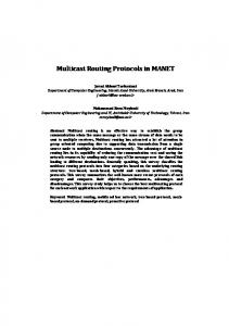
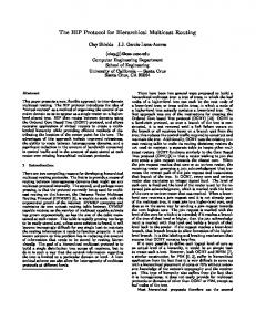
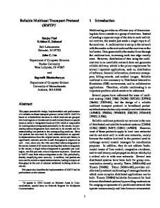
The relationship between the queuing delay, ρ, and the queue occupation is illustrated in Figures 1 and 2. Figure 1 shows that the queuing delay will increase as the ρ increases under the case of ρ > 1. Similarly, Figure 2 describes when ρ is fixed to 1.1, the queuing delay will increase as the queue occupation increases. With comprehensive analysis, it is obvious that the queuing delay of each MN significantly depends on ρ and queue occupations. Figure 1
The relationship of queuing delay and ρ (see online version for colours)
214
W-H. Hsu et al.
Figure 2
The relationship of queuing delay and queuing occupation (see online version for colours)
3.1 Route discovery process
2.2 Link delay computation The MAC protocol of IEEE 802.11 WLAN (IEEE Computer Society LAN MAN Standard Committee, 1999) concerns per-link communications. To avoid collisions, this mechanism uses a virtual carrier sense mechanism called Network Allocation Vector (NAV) to avoid potential unwanted interruptions when a data transmission performs. The NAV shows a busy state to other MNs within the transmission range. Those MNs will keep silent for the duration equal to the duration ID indicated in the packet header once they hear the NAV. Therefore, the NAV time unit is treated as a bandwidth reservation for media access. It shows that the NAV duration can reflect the state of busy media or traffic load (Zhang et al., 2003; Ozaki et al., 1999). Hence, the value of NAV in the MAC layer can be used to estimate the radio access delay. Assume n frames are delivered via the link between MNs k and l for a period of time. The link transmission delay Lk,l can be calculated as follows. Lk , l
∑ =
n i =1
NAVi
n
The route discovery process is similar to the work (Royer and Perkins, 1999; Toh et al., 2000). When a source of a multicast group has packets to send, it broadcasts a Multicast Route Discovery (MRD) packet throughout the network to initiate a multicast session for the multicast group. This MRD packet contains the multicast source address (also called identification, ID), the multicast group address, a unique sequence number, an empty delay record, an empty route record and Time to Live (TTL). When an intermediate MN receives the MRD packet, it first adds its own node ID, i.e., address, and delay information, i.e., the expected queuing delay and the link delay as shown in equations (5) and (6) to the route record and the delay record, respectively. Then, the intermediate MN creates a new entry in its multicast routing table to establish a reverse route. This reverse route entry may later be used to relay a Multicast Route Reply (MRR) packet back to the multicast source. Finally, the intermediate MN rebroadcasts the MRD packet to its neighbouring MNs. This process continues until the MRD packet reaches all the members of the multicast group. As a result, the MRD packet not only contains a list of traversed MNs, but also accumulates the sum of the queuing and link delays along the visited path. Therefore, the final queuing delay and link delay is the sum of individual queuing delay and link delay of each visited MN. Figure 3
The route discovery process in DBMRP (see online version for colours)
(6)
where NAVi represents the time duration needed in transmitting frame i, which is indicated in the Request-To-Send (RTS) control frame.
3
Multicast tree establishment
DBMRP is an on-demand multicast routing protocol used to establish a multicast tree in an ad hoc network. It is a source-based approach, i.e., the multicast routes are established on-demand by the source. Similar to most tree-based multicast protocols, a request phase and a reply phase are first responsibilities for the route discovery process. Then, a matrix, which is called Path Matrix (PM), is maintained by all MNs during the route set-up process. Finally, a proposed algorithm is used to locate all the DNs in the established multicast tree.
Notice that an intermediate MN or multicast member may receive more than one MRD packet for a given multicast source address or multicast group address. In this case, in our protocol, the intermediate MN or multicast member waits until they receive a certain number of MRD packets or a predetermined period of time. Then, it will choose an MRD packet with the smallest summation of queuing and link delays, and send an MRR packet back to the multicast source following the reverse path selected from the MRD packet record. Figure 3 describes the operation of route discovery process.
A novel Delay-Based Multicast Routing Protocol in ad hoc wireless networks
3.2 Route set-up process As mentioned before, each member of a multicast group will select a route with minimum delays and send an MRR packet back to the multicast source via the minimum delay route. Hence, several MRR packets (each one from different multicast member) will be received by the multicast source. Each MRR packet records the sum of delay of the traversed path and all visited MN IDs. Once the multicast source receives all MRR packets, it will use these recorded IDs to build a PM. Therefore, the PM constructs all the multicast routes from the multicast source to each multicast member. The PM is defined as follows. PM = {s (u , v) M x N |1 ≤ u ≤ M , 1 ≤ v ≤ N )},
(7)
where s(u, v) = k, k∈ {0, 1} and s(u, v) = 1 indicates there is a route between MNs u and v. The M rows and N columns of the PM represent the numbers of the multicast member and the on-tree MN, respectively. Taking Figure 4 for example, if the multicast source wants to send packets to all members, the path to multicast member 9 will be MN1 → MN3 → MN6. Figure 4
The illustration of PM (see online version for colours)
After building the PM, the multicast source propagates it along each path that each received MRR packet traversed. Each MN receiving the PM stores it, updates its multicast routing table and unicasts the PM to its downstream MNs. A multicast routing table contains a multicast group address, an upstream MN ID, a downstream MN ID and lifetime. All the intermediate MNs, which are responsible for forwarding the PM, update the multicast group address, the upstream MN ID and the downstream MN ID to their individual multicast routing table. On the other hand, all the multicast members only add the downstream ID to their individual multicast routing table. The lifetime is associated with each entry in the multicast routing table, indicating the length of time the route entry is valid. As a result, all the MNs in the established multicast tree have an
215
identical PM. In such case, the multicast tree has already been established.
3.3 The Displacement Node (DN) Owing to the reason of inability to exchange request-to-send or clear-to-send (RTS/CTS) and acknowledgement (ACK) packets with multiple receivers, it is difficult for IEEE 802.11 to support reliable multicast (Kuri and Kasera, 2001; Gupta et al., 2003). A receiver cannot receive a packet correctly if two or more packets are sent to it simultaneously, due to packet collision. This is a major problem for the reliability of multicast, as several members in a multicast group may simultaneously respond to a multicast-RTS or a data packet sent by a multicast source. As a result, a CTS or ACK collision will occur at the multicast source. To avoid the collisions mentioned earlier, it seems feasible to assign a specific recipient to send a CTS or an ACK. Actually, a combination of ACKs sent to attain a degree of reliability is often used in designing multicast protocols. Different methods have been proposed to provide reliable multicasting. For example, Probability-Based Protocols (PBPs) use probabilistic feedback schemes that allow each receiver to send an ACK immediately, with only a certain probability. In Delay-Based Protocols (DBPs), the recipient must wait a random amount of time before sending an ACK. Leader-Based Protocol (LBP) tackles the problem by electing a recipient node as a leader, and only this leader is allowed to send an ACK. It has been demonstrated that the LBP exhibits a higher throughput in comparison with PBP and DBP, which use traditional delayed feedback-based probabilistic methods (Kuri and Kasera, 2001). However, these three methods support only the infrastructure-based wireless networks. We propose an algorithm, which is based on LBP, to find DNs in the established multicast tree. The function of the DN is the same as the leader node described in LBP. Unlike the LBP, which elects only a leader node for a multicast group, the proposed algorithm may elect several DNs as leader nodes in a multicast group. With our algorithm, an MN within a multicast tree is elected as the DN if one of the following conditions is satisfied: •
it has more than two branches
•
it is a multicast member, and has a branch that connects to at least one multicast member.
For example, as shown in Figure 5, MNs 1, 2 and 3 are elected as the DN because they have more than two branches. Similarly, MN 4 is also elected as the DN because it has a branch that connects to multicast member MN 5.
216
W-H. Hsu et al.
The DNs in an established multicast tree can be easily found by checking the PM. Figure 5
Figure 6
The joining process in DBMRP (see online version for colours)
The selected DNs (see online version for colours)
4.2 Quit process
4
Multicast tree maintenance
Multicast tree reconfigurations are not required if the tree remains stable throughout the lifetime of the multicast communications. If the multicast tree is unstable, for example the multicast route breaks due to unpredictable node movement, then the multicast tree maintenance mechanism must be invoked. The maintenance mechanism in the DBMRP consists of three components: join process, quit process and route recovery process.
If a multicast group member MN wants to leave the multicast group, it sends a QUIT packet to its upstream MN. Upon receipt of the QUIT packet, the upstream MN checks if it has any downstream MN. If it has other downstream MNs, it simply deletes the member MN from the PM and downstream entries in the multicast routing table, and then broadcasts the updated PM to all on-tree MNs. Otherwise, it sends a QUIT packet to its upstream MN, and leaves the multicast group. Figures 7(a) and (b) show a Quit process example. In Figure 7(a), MN 1 sends a QUIT packet to MN 2 when it wants to leave the multicast group. Since the MN 2 has another downstream MN 5, it just deletes the MN 1 from the PM and the downstream entry in the multicast routing table, and then broadcasts the updated PM to all the on-tree MNs. Figure 7(a)
The quit process with downstream MNs (see online version for colours)
4.1 Join process Join process is invoked when a new MN wants to join the multicast group. The joining process finds the best on-tree MN, and establishes a path between the on-tree MN and the newly joining MN. All fields included in the MRD packet are similar to those illustrated in Section 3.1, except that the multicast source address is the new MN address. All Joining processes are the same as those illustrated in Sections 3.1 and 3.2. For the example shown in Figure 6, when an MN 1 wants to join a multicast group, it broadcasts an MRD packet to the MNs 2, 3 and 4. The MN 4 will rebroadcast the MRD packet to MN 5. The on-tree MNs 2 and 5 will then send their individual MRR packets back to MN 1. Suppose the MRR packet sent by the MN 2 contains the smallest sum of delay. Then, MN 1 will send a JQ RESERVE packet to MN 2. After receiving the JQ RESERVE packet, MN2 will update its PM, and broadcast the updated PM to all on-tree MNs. Finally, MN 1 will store the received PM and create its own multicast routing table.
In Figure 7(b), MN 1 sends a QUIT packet to MN 2 when it wants to leave the multicast group. Because MN 2 has no other downstream MNs, it just sends a QUIT packet to its upstream MN 3. When MN 3 receives the QUIT packet, it realises that it has still a downstream MN 4. Hence, the MN3 updates its PM and the downstream entry in the multicast routing table, and broadcasts the updated PM to all the on-tree MNs.
A novel Delay-Based Multicast Routing Protocol in ad hoc wireless networks Figure 7(b)
The quit process without downstream MNs (see online version for colours)
4.3 Route recovery process As MNs in an ad hoc network are capable of moving independently, a link has a limited lifetime. Furthermore, current existing links are no longer valid when any two MNs move out of transmission range each other. Therefore, a multicast tree is subject to disruption due to link/node failure, node mobility, or route expiration timers. In DBMRP, the route recovery process is responsible for repairing broken multicast links. An intermediate MN may fail or move. In this case, the multicast tree can break into two or more sub-trees. Similar to Royer and Perkins (1999) and Toh et al. (2000), the DBMRP also employs a localised repair strategy to deal with link breakage. As shown in Figure 8, when MN 1 moves out of the transmission range of the multicast source, the link between MN1 and the multicast source breaks. When a link breakage is detected, the upstream MN of the broken link broadcasts an MRD packet to all downstream MNs of the broken link to find new routes. These downstream MNs of the broken link can be easily found by checking the PM. In Figure 8, the multicast source will check the PM to find that MN 3 is the downstream MN of the broken link. The multicast source will broadcast an MRD packet to MNs 2, 4 and 5 to find a new route to MN 3. Since both MNs 2 and 4 know how to reach MN 3, they will send their individual MRR packets back to the multicast source. Note that this MRD packet differs from the MRD packet used in the route discovery process in one way: it has a limited TTL (i.e., limited hop count). The limited TTL can limit the broadcasting area, which reduces the communication overhead. Figure 8
The route recovery process in DBMRP (see online version for colours)
217
The upstream MN chooses a received MRR packet with the smallest sum of queuing and link delays, updates its PM and the downstream entry in multicast routing table, and then broadcasts the updated PM to all the on-tree MNs. In Figure 8, assume that the MRR packet sent by MN 4 has the smallest sum of delay. After receipt of all the MRR packets, the multicast source updates its PM and multicast routing table, and broadcasts the PM to all on-tree MNs. If the route recovery process fails, the lifetime of the broken multicast route in the multicast routing table of the upstream MN will expire. In this case, the upstream MN will send a route error packet to the multicast source. When the multicast source receives the error packet, it will establish a new multicast tree.
5
Simulation models and results
5.1 Simulation models and assumptions A simulated network with 50 MNs is randomly distributed in a rectangular coordinate grid of 1000 m × 1000 m. The radio propagation range for each MN is 250 m and the channel capacity is 2 Mbits/s. The link layer model is the Distributed Coordination Function (DCF) of the IEEE 802.11 wireless LAN standard. Each MN moves individually within a certain probability, and the probability of movement will initially be given by 0.1 and increased by 0.1 each movement until reaching 1. Each MN selects a random destination and moves there at a uniformly distributed speed in a predefined range of 0–30 m/s (0–108 km/hr). We assume that the mobility is high as the multicast group size increases. The TTL is fixed at 2. To reflect a realistic situation, each MN will stay at least 60 s in the new position after movement. The packet arrival rate of each MN will be given randomly, from 640 bps to 800 bps. The packet length considered in this simulation follows the statistical average packet size in real computer networks as 50–150 bytes long (Khalil et al., 1990). The buffer size of each MN will be given randomly, from 0.4 Kbytes to 1 Kbytes. The number of multicast members will initially be given by 5, and increase by 5 each movement until 35. The simulation platform is based on Free BSD, and C language is used to code the simulation environment. For each data point in the simulation result, 20 random graphs are generated. For each graph, a corresponding multicast tree is established and measured. Each reported data is calculated as the average of the 20 collected data. The various parameters used in our simulation are shown in Table 1. Table 1
Simulation parameters
Programming Language Simulation platform Channel Capacity MAC Layer Total number of MNs
C FreeBSD 2 Mbps IEEE 802.11 50
218
W-H. Hsu et al.
Table 1
Simulation parameters (continued)
Programming Language Simulation area Transmission range Mobility model Number of multicast member
C 1000 m × 1000 m 250 m 0~108 km/hr 5~35
Packet arrival rate
640~800 bps
Buffer size
0.4~1 Kbytes
TTL
Figure 11 The group size vs. average number of hops (see online version for colours)
2
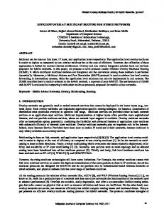
5.2 Simulation results Three different algorithms, MAODV, ODMRP and the proposed DBMRP, are evaluated and compared, as shown in Figures 9–12. Four performance measures are considered: packet delivery ratio, control overheads, average number of hops the data packet travels, and average end-to-end delay of the data packet. Figure 9
Figure 12 The group size vs. end-to-end delay (see online version for colours)
The multicast group size vs. packet delivery ratio (see online version for colours)
5.2.1 Packet delivery ratio
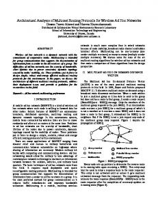
Figure 10 The group size vs. control overhead (see online version for colours)
The packet delivery ratio is defined as the mean number of data packets successfully received by multicast members to the number of data packets transmitted by the multicast source. Figure 9 presents the results with x-axis displaying the different multicast group sizes, and the y-axis displaying the packet delivery ratio. In the small multicast group size, DBMRP has the highest packet delivery ratio because it always selects the multicast route with a minimum end-to-end queuing delay plus link delay route to transmit the data to the multicast members. As the multicast group size increases, the packet delivery ratio for MAODV and DBMRP gradually decreases since the node mobility, i.e. high mobility, causes a frequent reconfiguration of the multicast tree. As a result, data cannot be forwarded until the route reconstruction process is completed. Actually, for most of the tree-based routing protocol, the more the number of multicast members, the higher the multicast route break probability will be.
A novel Delay-Based Multicast Routing Protocol in ad hoc wireless networks In contrast, ODMRP gets a higher packet delivery ratio than both MAODV and DBMRP when the multicast group size is 35. This is because the ODMRP is a mesh-based protocol, for which the forwarding group provides multiple paths, and periodically reconfigures its multicast forwarding group. Unlike ODMRP maintaining multiple paths, DBMRP needs to reconfigure broken routes once routes are broken since it only maintains one route. We notice that the gap between ODMRP (0.79) and DBMRP (0.75) is 0.04 when the group size is 35. Obviously, the gap 0.04 is not large. Nevertheless, this little improvement will cost a lot of control overheads when the group size is 35 as shown in Figure 10, where the gap of number of control packets between ODMRP (= 9765) and DBMRP (= 3942) is 5823 packets. This result indicates that DBMRP is suitable for multicast transmission in ad hoc networks when group size is large because more control overheads will dramatically decrease the maximum packet delivery ratio of the ad hoc networks.
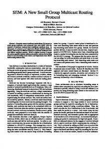
5.2.2 Control overhead The control overhead is defined as the total number of control packets transmitted during the multicast tree establishment and maintenance. Each control packet includes unicast packets, e.g., RREP, MRR, other tree maintenance packets, and broadcast packets, e.g. RREQ, MRD. Figure 10 shows the comparison of control overheads based on different multicast group sizes. The x-axis represents the different multicast group sizes whereas the y-axis shows the control overheads (number of control packets). The control overhead produced by MAODV and DBMRP is significantly lower than that by ODMRP. This is because the multicast tree is established and maintained on-demand in MAODV and DBMRP, and do not maintain multiple routes to a same destination. It is obvious that the total number of control packets produced for each multicast session depends on the total number of tree reconfigurations. Since the total number of tree reconfigurations made by MAODV and DBMRP are smaller than that of ODMRP, both MAODV and DBMRP provide better performance than ODMRP. Furthermore, the DBMRP provides the best performance of control overhead. This is because the DBMRP only send the MRD and MRR packets after tree reconfiguration instead of broadcasting a group hello packet in MAODV. For a larger multicast group size, it is obvious that the gap of the number of control overheads between these two protocols is also large. Clearly, the ODMRP performs the highest control overhead because it uses a soft state approach to maintain connectivity among multicast members. As a result, the MNs in a multicast tree must periodically generate control packets. For example, to refresh the membership information and update the routes, the JQ packet is periodically flooded in the network, regardless of whether the multicast tree is stable.
219
5.2.3 Average number of hops Figure 11 shows the average number of hops under different multicast group sizes. Since both MAODV and ODMRP have almost the same performance, we only compare ODMRP with DBMRP. From the results, the value of the average hop count is approximately 2.297 for ODMRP and 3.161 for DBMRP. In most scenarios, ODMRP results in a smaller number of hops than DBMRP because ODMRP broadcasts the data packets through its forwarding group and the first surviving packet to the receiver is taken. Usually, this smallest delay path implies shortest-hop path in long-delay link, much like the wireless physical links in our simulation. On the other hand, since DBMRP selects a path based on the smallest delay, the resulting path is normally longer than the shortest-path.
5.2.4 End-to-end delay The end-to-end delay is measured when packets have been successfully received by the multicast members. Since MAODV and ODMRP have almost the same performance, we only focus on ODMRP and DBMRP under different multicast group sizes. The results show that the mean of end-to-end delay is 86.606 ms for ODMRP, and 76.893 ms for DBMRP, as shown in Figure 12. Clearly, the ODMRP produces a longer end-to-end delay than DBMRP. This is because packets are periodically broadcast in the ODMRP, and it is quite easy to collide with other broadcast packets being transmitted during the same period of time. On the other hand, the multicast route is selected by the DBMRP based on minimum delay from the multicast source to multicast member. In addition, the DNs also plays a key role in reducing the number of control packets in a multicast tree; therefore, there is little control packet collision. The result of end-to-end delay can correspond to previous result on the average number of hops. It is obvious that ODMRP chooses the shortest multicast path, but has a longer end-to-end delay. On the other hand, DBMRP chooses a longer multicast route, but has a smaller end-to-end delay.
6
Conclusions
This paper proposes a novel DBMRP for mobile ad hoc networks. DBMRP is based on tree forwarding and an on-demand source-based multicast routing protocol, and uses queuing and link delays for each visited MN to establish the multicast tree. It also uses the DNs to reduce the number of control packets in an established multicast tree, and the PM to provide an efficient method for local error recovery in route recovery processes. Simulation results show that ODMRP has better packet delivery ratio than the other two algorithms in high mobility, but incurs extremely large control overhead. On the other hand, DBMRP exhibits good packet delivery ratio at low mobility, and has the smallest control overhead
220
W-H. Hsu et al.
and end-to-end delay than ODMRP. In addition, the average number of hops for DBMRP is only slightly higher than ODMRP. Hence, the DBMRP can achieve high multicast efficiency with low communication overhead and end-to-end delays, when compared with the other two multicast routing protocols.
References Cordeiro, C.M., Gossain, H. and Agrawal, D. (2003) ‘Multicast over wireless mobile ad hoc networks: present and future directions’, IEEE Network, Vol. 17, No. 1, January–February, pp.52–59. Dhillon, H. and Ngo, H.Q. (2005) ‘CQMP: a mesh-based multicast routing protocol with consolidated query packets’, Proceedings of IEEE WCNC 2005, Vol. 4, March, pp.2168–2174. Gupta, S.K.S., Shankar, V. and Lalwani, S. (2003) ‘Reliable multicast MAC protocol for wireless LANs’, Proceedings of IEEE ICC’03, May, pp.93–97. IEEE Computer Society LAN MAN Standard Committee (1999) ‘Wireless LAN medium access control MAC and physical layer specifications, IEEE Std 802.11’, The Institute of Electrical and Electronics Engineers, Piscataway, NJ 08855-1331, USA. Khalil, K.M., Luc, K.Q. and Wilson, D.V. (1990) ‘The LAN traffic analysis and workload characterization’, Proc. ACM Local Computer Networks 1990, Vol. 202, Article 5, September, pp.112–122. Kuri, J. and Kasera, S.K. (2001) ‘Reliable multicast in multi-access wireless LANs’, Wireless Networks, Vol. 7, No. 4, July, pp.359–369. Lee, S.J., Gerla, M. and Chiang, C.C. (1999) ‘On-demand multicast routing protocol’, Proceedings of IEEE WCNC’99, New Orleans, LA, September, pp.1298–1302.
Obraczka, K. and Tsudik, G. (1998) ‘Multicast routing issues in ad hoc networks’, Proceedings of IEEE ICUPC ‘98, October. Badarneh, O.S. and Kadoch, M. (2009) ‘Multicast routing protocols in mobile ad hoc networks: a comparative survey and taxonomy’, EURASIP Journal on Wireless Communications and Networking, Vol. 2009, pp.1–42. Ozaki, T., Kim, J.B. and Suda, T. (1999) ‘Bandwidth-efficient multicast routing protocol for ad-hoc networks’, Proceedings of IEEE ICCCN’99, October, pp.10–17. Royer, E.M. and Perkins, C.E. (1999) ‘Multicast operation of the ad-hoc on-demand distance vector routing protocol’, Proceedings of the 5th ACM/IEEE Annual Conf. on Mobile Computing and Networking, Seattle, Washington, USA, August, pp.207–218. Sisodia, R.S., Karthigeyan, I., Manoj, B.S. and Murthy, C.S.R. (2003) ‘A preferred link based multicast protocol for wireless mobile ad hoc networks’, Proceedings of IEEE ICC’03, May, pp.2213–2217. Toh, C-K., Guichala, G. and Bunchua, S. (2000) ‘ABAM: On-demand associativity-based multicast routing for ad hoc mobile networks’, Proceedings of IEEE VTC 2000, September, pp.987–993. Varshney, U. (2002) ‘Multicast over wireless networks’, Communications of ACM, Vol. 45, No. 12, December, pp.31–37. Zhang, Q., Guo, C., Guo, Z. and Zhu, W. (2003) ‘Efficient mobility management for vertical handoff between WWAN and WLAN’, IEEE Communications Magazine, Vol. 41, No. 11, November, pp.102–108. Zhou, J., Li, J., Li, X. and Cao, F. (2008) ‘Timer forecasting zone based on demand multicast routing protocol in mobile ad hoc network’, Proceedings of ICCS 2008, November, pp.1712–1715.