Behavior Research Methods, Instruments, & Computers 2002, 34 (3), 399-407
A novel rotometer based on a RISC microcontroller F. J. HEREDIA-LÓPEZ, J. L. BATA-GARCÍA, F. J. ÁLVAREZ-CERVERA, and J. L. GÓNGORA-ALFARO Universidad Autónoma de Yucatán, Mérida, Mexico A new, low-cost rotometer, based on a reduced instruction set computer (RISC) microcontroller, is presented. Like earlier devices, it counts the number and direction of full turns for predetermined time periods during the evaluation of turning behavior induced by drug administration in rats. The present stand-alone system includes a nonvolatile memory for long-term data storage and a serial port for data transmission. It also contains a display for monitoring the experiments and has battery backup to avoid interruptions owing to power failures. A high correlation was found (r . .988, p , 2 3 10214) between the counts of the rotometer and those of two trained observers. The system reflects quantitative differences in turning behavior owing to pharmacological manipulations. It provides the most common counting parameters and is inexpensive, flexible, highly reliable, and completely portable (weight including batteries, 159 g).
One of the most frequently used models in the study of the physiology of the basal ganglia is based on the turning (or circling) behavior induced by drug administration in animals with unilateral lesion of the nigrostriatal dopaminergic pathway (Glick, Jerussi, & Fleisher, 1976; Pycock, 1980; Ungerstedt, 1971; Ungerstedt & Arbuthnott, 1970). This experimental model, which has been compared with human hemiparkinsonism (Duvoisin, 1976), has been very useful in understandingthe physiopathologyof Parkinson’s disease (Duvoisin, 1976; Perese, Ulman, Viola, Ewing, & Bankiewicz, 1989), as well as for the evaluation of the therapeutic potential of drugs (Kebabian et al., 1992). The turning behavior model has been used to test the functionality of brain tissue implants as a means for correcting the neurological deficits caused by the degeneration of dopaminergic neurons (Björklund, Dunnett, Stenevi, Lewis, & Iversen, 1980; Brundin et al., 1988; Dunnett, Björklund, Schmidt, Stenevi, & Iversen, 1983; Horellou, Marlier, Privat, & Mallet, 1990) and has provided the basis on which to start clinical trials in humans (Backlund, Olson, Seiger, & Lindvall, 1987; Brundin et al., 1987). In the last few years, some studies of the physiology of the basal ganglia in the rat brain have been based on this model in combinationwith the unilateral injection of drugs into the substantia nigra (Bata-García, Heredia-López, Álvarez-Cervera, Arankowsky-Sandoval, & GóngoraAlfaro, 2002). Circling behavior is commonly evaluated by placing the animal inside a flat or concave-bottomed enclosure. Carlson and Glick (1996) have found that the type of bottom This study was supported by CONACYT-Mexico Grants 1831M9211 and 31377-N to J.L.G.-A. Correspondence concerning this article should be addressed to F. J. Álvarez-Cervera, Laboratorio de Neurofisiología, Centro de Investigaciones Regionales “Dr. Hideyo Noguchi,” Universidad Autónoma de Yucatán, Av. Itzaes Nº 490 3 59, Mérida, Yucatán, C.P. 97000, Mexico (e-mail:
[email protected]).
is irrelevant to the characteristics of the turning behavior. The rotational movement of the subject is detected directly or indirectly by means of some type of sensor (optoelectronic, magnetic, resistive, mechanical, or video camera) or by direct observation. The direction of turning is designated as either contraversive (opposite side to the lesion) or ipsiversive (same side as the lesion). Net turns or net rotations result from subtracting the number of turns in the less preferred direction from those in the dominant direction. The easiest way to evaluate turning behavior is to have a trained observer count the number of full turns performed by the animal in specified time intervals, until the turning behavior disappears. The main disadvantage of this direct approach is that observation times are lengthy (typically, 2 h or more). In addition, counting mistakes owing to distraction or fatigue are possible, as well as subsequent data transcription errors. Likewise, the presence of the experimenter in the test room can be a distracting influence on the behavior of the animals under study. Various approaches for automatically measuring turning behavior in rodents have been used. These devices, also referred to as rotometers, can be broadly grouped into the following two categories: mechanical harnesses or strings, which transmit the rotational movement to some type of detector and counter, and video tracking systems. The first class comprises systems that provide results in printed form or on a dial (Barber, Blackburn, & Greenwood, 1973; Greenstein & Glick, 1975; Heredia-López et al., 1992; Jerussi, 1982; Schwarz, Stein, & Bernard, 1978; Ungerstedt & Arbuthnott, 1970), as well as instruments that are able to save data electronically (D’Anna et al.,1989; Hudson, Levin, & Hoffer, 1993; Kulmala, Boja, & Hutton, 1987; Pons, López, Ramis, Planas, & Rial, 1990; Richards, Sabol, & Freed, 1990; Schmidt & Dubach, 1988). Earlier systems presented some disadvantages, such as not being able to distinguish between contraversive and ipsiversive turns (Ungerstedt & Arbuthnott,
399
Copyright 2002 Psychonomic Society, Inc.
400
HEREDIA-LÓPEZ, BATA-GARCÍA, ÁLVAREZ-CERVERA, AND GÓNGORA-ALFARO
1970) or offering only a printed report of the recorded turns (Barber et al., 1973; Heredia-López et al., 1992; Schwarz et al., 1978). Some of the first versions also had problems when incomplete oscillatory turns were dealt with, but this inconvenience was overcome in a more recent prototype (Greenstein & Glick, 1975), and another one could record partial turns of any angle (Schwarz et al., 1978). Another prototype was able to indicate the duration of each turn, as well as to record 180º direction reversals, but the output was a printed trace from an external event recorder and required interpretation. This rotometer also included a mechanical revolution counter for displaying net rotations (Jerussi, 1982). Some systems are prepared to handle several chambers simultaneously (D’Anna et al., 1989; Hudson et al., 1993; Kulmala et al., 1987). Others are designed to work with larger animals, such as primates (Schmidt & Dubach, 1988). In addition to recording turning behavior, another scheme can keep track of motor activity and some stereotyped movements (Pons et al., 1990). Besides, there is a report of a custom-made rotometer for conditioned rotation studies (Richards et al., 1990). Video tracking systems include an associated computer, and some have the capability to classify turns of several diameters and to record locomotion simultaneously (Bonatz, Steiner, & Huston, 1987). These systems consist of a computer, a video interface, and a camera, in addition to the animal chamber, thus entailing a high cost. For some of them, the background color of the chamber has to contrast with the color of the rat in order to generate a detectable signal. In addition, unwanted light reflections (e.g., by urine) can provoke false positive signals. With one particular device, turning behavior is expressed in different diameter classes and as partial or full turns (Schwarting, Goldenberg, Steiner, Fornaguera, & Huston, 1993). Nevertheless, since the video tracking system approach does not include a rat harness, animal stress is reduced. However, some of these devices do not include all of the necessary experimental features, thus restricting their use. Likewise, the availability of such instruments is, in many laboratories, limited owing to their high cost. A commercial stand-alone rotometer for one animal may sell for several thousand dollars, whereas a similar unit designed for use with a personalcomputer (PC) could exceed $10,000. The expense is further elevated in some cases by the requirement of costly hardware, such as a dedicated PC, a data acquisition or interface card, a recorder or printer, and a video camera. This was the main reason for designing a low-cost electronic rotational counting system that can record results automaticallyand dependably. Here, we describe a rat rotometer, which uses a reduced instruction set computer (RISC) microcontroller ( mC), has a nonvolatile memory for data storage, and incorporates a rechargeable battery pack. The data stored in memory may be easily transferred via serial port to a PC for analysis. The battery backup overcomes the inconvenience of losing valuable experimental data caused by power failures. All the parts were obtained in the local market at a
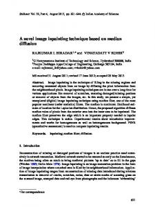
low cost ($60.00). The RISC rotometer has the capacity to count and discriminate the number and direction of full turns performed by rats in a previously selected time interval (TI), which is repeated for a specified total experimentation time (ET). This avoids the need to have a trained observer to follow the experiment. METHOD Hardware Description The completed prototypeweighs 159 g, includingthe integrated rechargeable batteries. It measures 11.5 cm (4.5 in.) 3 5.5 cm (2.2 in.) 3 2.5 cm (1 in.). The RISC rotometer can be divided into seven main sections (Figure 1), as follows. The references to the parts making up each section correspond to the labels used in Figure 2. Transducer module (TIL111 optoisolators,labeled ISO1 to ISO3) Reduced instruction set computer (RISC) microcontroller (PIC16C84, U1) Dot matrix liquid crystal display (LCD; AND491, U2) 64K of electricallyerasable programmable read only memory (EEPROM; 24C65, U3) Transistor–transistor logic (TTL) RS232 serial communication converter (MAX232, U5) Keyboard (consisting of switches SW1 to SW3) Power supply (built around an LM317L adjustable voltage regulator, U6; an LM78L05 fixed-voltage regulator, U4; and rechargeable batteries, BT1 and BT2).
Transducer module. The transducer module is based on three optoisolatorsand a mechanical system (Figure 3). Each optoisolator consists of an infrared light-emitting diode (LED) and a phototransistor. The optoisolator assembly is housed in a sealed compartment that prevents stray light, humidity, and dust from entering. The mechanical system transmits the circular movement of the rat by means of a steel wire. One end of this wire is hooked to a small lug, which is attached to a harness that is f ixed around the chest of the rat. The other end of the wire is attached to a second lug, which, in turn, is fixed to a steel disk that spins in accordance with the rotations of the rat. The disk is mounted on a ball bearing to reduce friction. As the disk turns, a small triangular piece of black aluminum, perpendicularly affixed to the same shaft as the disk, occludes the infrared beams within the optoisolators. The sequence in which the optoisolators are obstructed is related to the direction and completeness of each turning movement performed by the rat. The detectors (Motorola, Phoenix, AZ) produce electric signals that are read by the RISC mC (Microchip, Chandler, AZ) and processed by a software program to determine when a completed turn happens and to specify its direction. RISC microcontroller. A PIC16F84 mC (Microchip) was chosen because of its low cost, programming ease, and versatility. This device is considered a reduced instruction set microcomputer. That is, it belongs to a family of
NOVEL ROTOMETER
401
Figure 1. RISC rotometer block diagram.
processors that are fast, as well as easy and inexpensive to manufacture. This integrated circuit (IC) in particular, named U1 in Figure 2, has two fully programmable ports, identified as A and B. Port A is 5 bits long, and Port B is 8 bits long. In this application, both ports are fully used. The first 4 bits (RA0, RA1, RA2, and RA3) of Port A are
used as a data bus for the LCD, while the fifth bit (RA4) is used to supply clock pulses to the EEPROM (U3). The first 2 bits of Port B (RB0 and RB1) are used to read the input signals from the transducer module, whereas bits RB2, RB3, and RB4 are used to read the keyboard switches (SW1 to SW3). RB4 is simultaneously used as a 1-bit data
Figure 2. RISC rotometer circuit schematic.
402
HEREDIA-LÓPEZ, BATA-GARCÍA, ÁLVAREZ-CERVERA, AND GÓNGORA-ALFARO
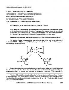
Figure 3. Transducer module schematic. From “Girómetro, un sistema electrónico automático para contabilizar y discriminar giros completos en ratas,” by F. J. Heredia-López, F. J. Álvarez-Cervera, J. L. Góngora-Alfaro, L. MendozaCamargo, L. Chacón-Gutiérrez, and C. Luján-Ramirez, 1992, Revista Biomédica, 3, p. 185. Copyright 1992 by Centro de Investigaciones Regionales. Adapted with permission.
bus between the EEPROM and the mC. The remaining three bits (RB5, RB6, and RB7) are used to control the LCD (U2). RB5 also serves as the serial port line. Dot matrix LCD. A low-cost AND 491 display was used (AND, Burlingame, CA). This device presents two lines of symbols, consisting of 16 characters each. The display is controlled by a configurable data bus (4 or 8 bits wide) and three control lines. We used the 4-bit bus mode. 64 K EEPROM. This storage media is a nonvolatile memory (24C65, Microchip) that does not require a permanent power supply. It can hold saved information for up to 10 years without external power. Because of this feature, battery replacement is possible without disturbing the information stored in memory. Data may be written or erased by using commands from the mC. Two communication buses are available: parallel and serial. For the latter, two main protocols are possible: serial protocol interface (SPI), which makes use of three signals for communication, and integrated-integrated communication (IIC), which uses only two signals. The latter type was selected because of the limited number of port control bits available in the mC. The experimental data for each time interval are stored in 4 bytes (16 bits) of memory: 2 bytes for the tally of ipsiversive turns and 2 bytes for the count of contraversive turns. In addition, 4 bytes are required to record the experiment header. This includes the specified values for the TI and the ET. The selected storage capacity (64 Kbits) allows saving up to 17 h of continuous experimentation, using a TI of 1 min. However, for the more commonly used 5-min intervals, ET may last up to 3.5 days. In case
the totality of memory locationsare occupied, data recording is suspended, and a visual warning is issued (the display shows the option for data transfer to the PC). Apart from the technical specifications of this device, its low cost was also considered. TTL to RS232 converter. Serial information sent by the mC through the RB5 terminal has TTL levels (0 and 5 V) that are not compatible in amplitude with the RS232 standard. The function of the RS232 converter is to translate the TTL signals from the mC into RS232 standard levels. Hence, a high TTL level is translated into a voltage level of between 23 and 215V, whereas a low TTL level is shifted into a voltage level of between 13 and 115 V. A MAX232 IC (MAXIM), labeled U5 in Figure 2, was used in this section, since it only needs 15 V to generate the required voltages and because of its low cost. Keyboard. The keyboard in this design is very simple. It consists of only three pushbutton switches. With this set of keys, all functions in the device are controlled by means of a menu displayed on the LCD screen. The first switch is the Enter key, and is used to confirm selections. The second key is called Y/1, and has a double function. It is used to respond affirmatively (Y 5 yes) to a displayed question or to increase (1) a displayed numerical value. Finally, the third key, which also has two functions, is identified as N/2. It is pressed to answer negatively (N 5 no) to a displayed question or to decrease (2) a displayed numerical value. Power supply. A commercial AC/DC power adapter with an output voltage of between 12 and 30 V at 300 mA is used. This voltage is limited to 9 V by means of an ad-
NOVEL ROTOMETER justable voltage regulator (U6). The 9 V output is sent through a rectifier diode (D3) and a resistor (R9) to an array of two dual Ni-Cd rechargeable batteries (BT1, BT2) and is also routed into a 15 V regulator (U4), which supplies power to all the circuits described above. The purpose of the rectifier diode is to prevent battery discharge through the bias circuitry associated with the adjustable voltage regulator during power failure conditions.The series resistor limits the charging current entering the battery array. The batteries are connected in a serial/parallel configuration so as to yield 7.2 V, while at the same time doubling the available current capacity. When a drop in the conventional power supply occurs, the backup supply immediately goes into operation. This prevents the loss of stored experimental conditions and collected data. Because of the low power consumption of most of the circuits used, the batteries can supply power for at least 2 continuous hours of use, which is more than enough for most power failure situations. Software for Instrument Control and Data Transfer Since the developed device uses a microcontroller, a software program is stored internally to control its operation. This program was developed using the specific assembly language of the mC. Besides, for serial information transfer to the PC, a program in C11 language (Borland Builder C11, Scotts Valley, CA) was developed to read the serial information from the RISC rotometer, to save it on the hard disk of the PC, using a specific format in an ASCII (American Standard Code for Information Interchange) file, and to generate the corresponding plot. Microcontroller software. This program performs the following tasks. 1. It configures the mC ports. 2. It configures the LCD for a 4-bit data bus. 3. It shows an identification message on the first line of the LCD and displays the option to start a new experiment on the second line. Then the answer from the keyboard is read. 4. In accordance with the previous answer, either a new experiment starts, or the user is asked whether he or she wishes to send the information from the previous experiment to the PC. 5. In case a new experiment is to begin, a message asking for the TI for counting turns is displayed. By default, the time interval (INT) from the previous experiment is shown. The complete displayed message is INT: ####, where #### represents any four-digit numerical value. To increase the duration of the TI, the user needs to press the Y/1 key. To decrease it, the N/2 key should be pressed. The acceptable range of values for INT is 1–255 min. Once the desired value is displayed, the Enter key is pressed for confirmation. This value is saved in the EEPROM, in two sequential locations. Next, a message asking for the total duration of the test, or ET, is displayed, and the previously used value (in minutes) is shown by default: ET: ####. The value for ET can be chosen from between 1 and 5,500 min (equivalent to about 92 h, or 3.8 days).
403
The keyboard is read, as in the previous case, and the accepted value is stored into the following two memory locations. 6. The next step is to clear the display and show the following data: ET: #### LT:0000
INT: #### RT:0000
ET is the total experimental time in minutes, INT is the time interval in which to total and save counted turns, LT is the number of full left turns (counterclockwise), and RT is the number of full right turns (clockwise). Over 1,000 turns per TI may be recorded. Immediately, the internal timer of the mC is initialized to count time periods of 66.66 msec, and the experimental time count begins. After each of these terms, an interruption is produced. These interruptions are counted in order to obtain the equivalent time in seconds and minutes, so the system can determine when the elapsed time is equal to the programmed TI and then save the number of completed turns in each direction in memory. This time keeping is also used to check whether the programmed experiment duration has been reached. When this happens, the counts for the last interval are saved in memory, as well as the total number of data items (corresponding to the number of programmed intervals). Finally, the question of whether to send data to the PC at this time is displayed. During the process described above, logical signals RB0 and RB1 from the transducer module are read (Figure 1). In accordance with the sequential activation and the previous states of these signals, the completion and direction of each turn is determined. When a full turn (360º) is completed, the corresponding count is increased and displayed in the LCD. Incomplete turns (oscillations) are discarded by the program logic. When a TI has elapsed, the count indications in the LCD are automatically reset for the next interval. Since the time for displaying data in the LCD is relatively long, this routine is used as a debouncer for the signals from the transducer module. Finally, during these tasks, the RB1 (Enter key) terminal is read in case the user wants to interrupt the experiment. 7. After the end (or interruption) of the experiment, the next step is to show a message asking whether the collected data are going to be sent to the PC at this time. The displayed message is “Transfer to PC? Y/N.” Then, the keyboard is read to obtain the answer. If the answer is yes, indicated by pressing the Y/1 key, the user must previously have connected the device by means of a cable to the serial port of the PC, and on this PC the program for data communication must be running and displaying the following message: “Waiting for data.” At this time, the LCD will be cleared (to signal the start of the serial transmission), and the data stored in the RISC rotometer memory will be sent to the PC. Communication starts by automatically sending an identificationcharacter (U), followed by 2 bytes of data containing the count value for the first interval and a Return character. After each pair of bytes
404
HEREDIA-LÓPEZ, BATA-GARCÍA, ÁLVAREZ-CERVERA, AND GÓNGORA-ALFARO
holding count values for successive intervals, a Return character is inserted. This process continues until the end of the stored data is reached. Finally, a stop character (I) is sent. At this point, the program returns to Step 3 above. If the answer to the “Transfer to PC? Y/N” question is negative, indicated by pressing the N/- key, the data will remain in the device memory for later transfer to the PC. However, it should be stressed that nevertheless, stored data must be transmitted to the PC before a new experiment is initiatedor, else, they will be lost. This feature forces the user to make a permanent backup of experimental data prior to starting a new rotational behavior test. Also worth mentioning is the fact that serial communication is performed by default through Serial Port 2 (COM2) to avoid interfering with the mouse controller (usually connected to COM1). Apart from the main tasks already described, the program in the mC performs secondary chores, such as (1) writing the LCD module commands by generating the corresponding logical signals, converting the data byte into low and high nibbles, and sending them (along with this, the mC must also read the task completion flag from the LCD), (2) reading or writing values in/from the EEPROM by generating the appropriate IIC signals, (3) translating data from binary to BCD and vice versa, and translating BCD data to its ASCII values before sending them to the PC, and (4) generating the serial code for an RS232 transmission to allow the communicationbetween the RISC rotometer and the PC. Personal computer program. The data transfer program for the PC, written in C11, is Windows based and performs the following tasks. 1. It configures the serial port of the PC with the same protocol assigned to the RISC rotometer: 1200 baud, 8 bits, NP. 2. It checks the incoming data to determine whether it is a new experiment or the continuation of a previous one. 3. It reads data from the serial port. 4. It saves incoming data in a temporary ASCII file. This file already exists if this is the continuation of a previous experiment; otherwise, the file is created. 5. It asks the user if the received data are the last in the experiment or not. If the answer is yes, data are saved in ASCII format in a new file in table form (compatible with MicroCal’s ORIGIN graphical analysis software). The file contains the header with the most relevant experimental identification data. However, if additional data from the same experiment are going to be received at a later time, the program remains in standby mode or may be interrupted, permitting the use of the PC for other tasks and keeping the received data in the temporary file. New data will be appended in subsequent transmissions. Once the last data are received and the final file has been created, the temporary file is deleted. 6. It produces a plot of turns per minute versus time. 7. It permits printing of data files or preliminary plots of turns per minute versus experimental time. Both the mC software and the PC software are available as e-mail attachment files from the corresponding author.
Experimental Evaluation Animals and environment. In all the experiments, adult male Wistar rats, raised in our own facilities, were used. All the animals were housed in individual acrylic cages, and food and water were available ad lib. They were adapted to a 12:12-h light:dark cycle (subdued lights on at 7:00 a.m.) for 7 days. Temperature and air circulation were automatically controlled in the test room (Heredia-López, Bata-García, & Álvarez-Cervera, 1997). Circling behavior data collection was performed between 08:00 and 16:00 hours. All efforts were made to minimize animal suffering, according to the recommendations of the Guide for the Care and Use of Laboratory Animals (National Research Council, 1996). Dopaminergic pathway lesion. First, the rats were anesthetized using sodium pentobarbital (45 mg/kg, i.p.) and placed in a stereotactic frame (Stoelting), with the incisive bar at 3.3 mm under the interaural line (Paxinos & Watson, 1986). Next, a dose of desipramine (15 mg/kg, i.p.) was administered to protect noradrenergic neurons from the neurotoxic lesion that was due to 6-hidroxydopamine (6-OHDA). Methylatropinewas then injected (0.1 mg/kg, i.m.) to avoid bronchial secretions during surgery. A 2% lidocaine solution with epinephrine (5 mg/ml) was applied in the surgical area to reduce bleeding. Thirty minutes after the injection of desipramine, 3 ml of a 6-OHDA solution (2 mg/ml), containing ascorbic acid (0.5 mg/ml) to prevent its spontaneous oxidation, was administered directly to the substantia nigra pars compacta (right side). The coordinates for the injection were the following: anteroposterior, 25.6 mm from bregma; lateral, 22.0 mm from the midline; and dorso-ventral, 27.4 mm from the dura. In order to reduce the lesion to the dopaminergic neurons of the ventral tegmental area, the needle bevel was oriented toward the pars compacta (Perese et al., 1989). The injection was performed during a period of 15 min, at steps of 0.1 ml/30 sec. To allow proper diffusion of the neurotoxin, the cannula was left in place for an additional minute before withdrawal (Perese et al., 1989). At the end of the surgery, each rat was injected with penicillin (300,000 UI/kg, i.m.) to prevent infection. Turning behavior. Turning behavior was evaluated 14 days after the neurotoxic lesion with 6-OHDA. Each animal was placed in a flat-bottomed plastic circular container (40 cm in diameter and 35 cm high). The transduction of movements was done by means of a flexible stainless steel wire, one end of which was attached to a harness placed around the torso of the rat, and the other end to the corresponding lug on the RISC rotometer. Each animal was habituated to the container for about 20 min. Then, apomorphine, a dopaminergic agonist that induces turning behavior in animals with unilateral lesion of the nigrostriatal pathway, was injected subcutaneously (0.25 mg/kg). At the time of injection, the start button on the RISC rotometer was pressed to initiate the automatic counting and the experimental time clock. The rotometer was programmed to count turns in 1-min intervals and for an ET of 90 min. Simultaneously, a video camcorder was turned on to save the experiment on film for later analysis by two
NOVEL ROTOMETER observers, who independently counted the contraversive and ipsiversive full turns. For the purpose of evaluating the performance of the RISC rotometer, only the rats that presented a clear turning behavior were considered. Aside from this issue, the 5 rats to be included in the assessment were randomly selected. Drugs. Drugs were dissolved in buffered saline solution (pH 7.4) 30 min before the injection. The physiological buffered saline (PBS) solution was composed of the following (in mM/l): NaCl, 136.9; KCl, 2.7; Na2HPO 4, 6.25; KH 2PO4, 1.5, with pH adjusted to 7.4. Since desipramine (RBI, Natich, MA) is not soluble in PBS, it was dissolved in a 12.5% dimethylsulfoxide(DMSO) solution in deionized water. Apomorphine hydrochloride (Sigma, St. Louis, MO) was dissolved in deionized water within 10 min of administration. RESULTS In 5 rats with unilateral lesions of the dopaminergic pathway, the application of apomorphine induced an intense contraversive turning behavior. Given that an exact timebase is used in the rotometer, rotational speed (in turns per minute or other time lapse) can easily be derived. Figure 4 shows five examples of the time course of turning behavior, as recorded by the RISC rotometer and the two independent observers. From the plots on this figure, it can be seen that, in all cases, there was an excellent correspondence between the number of turns in 5-min intervals counted by the two observers and those recorded by the RISC rotometer. The linear regression analysis of the
405
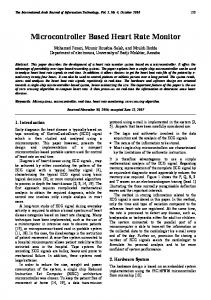
number of turns recorded by the automatic rotometer with respect to those counted by each observer yielded correlation coefficient values of between .9889 and .9989 for the five 90-min experiments (statistical significance, p, was between 1.2 3 10214 and 7.6 3 10223). The one-toone relation between the counts reported by the RISC rotometer and the average obtained from the counts recorded by the two observers is evidenced by the slope and xoffset values rendered by the regression equations. These values ranged from 0.92 to 0.98, and from 20.29 to 0.14, respectively. Likewise, the cumulative number of turns recorded by the RISC rotometer, as well as by the two independentobservers, for the five 90-min experiments that were studied is shown in Figure 5. Some disparities in counting between the observers and the RISC rotometer could be detected. These differences were small; the counts from either observer frequently exceeded the RISC rotometer counts by one or two units per 5-min interval. In the worst-case situation, there was an absolute difference of 5 counts from a total of 34 (15%) in an interval. The largest percent difference was found to be 20% for any interval with more than 10 counts. Fifteen intervals (out of 108) with smaller numbers of counts showed differences larger than 20%. That is, these discrepancies could be proportionally larger for those intervals in which the number of turns was low (e.g., 4 counts vs. 5 represents a 25% variation). The performance of the RISC rotometer at counting the total number of contraversive turns is reflected in the data used to make the column plot in Figure 5. In particular,
Figure 4. Five examples of the time course of turning behavior, showing the close correspondence between the number of turns counted by two observers and those obtained by the RISC rotometer.
406
HEREDIA-LÓPEZ, BATA-GARCÍA, ÁLVAREZ-CERVERA, AND GÓNGORA-ALFARO
Contraversive turns /90 min
500
RISC rotometer Observer 1 Observer 2
400 300 200 100
Rat:
0
L15
L19
L25
L42
L68
Figure 5. Comparison between the total number of full turns counted by the RISC rotometer and by two independent observers during 90 min of experimentation for 5 treated rats.
the largest absolute discrepancy (corresponding to Rat L42) in total counts was 30 (out of 360), representing an 8.3% difference. DISCUSSIO N AND CONCLUSIONS A comparison between the data collected by the rotometer and the counts obtained by the trained observers reflects a high degree of confidence for the rotometer performance at counting completed turns in both directions. Minor counting disparities were found, however, but these may be attributed to the difference, between the rotometer and a trained observer, in selection of a starting position of the rat as a reference point for detecting a full turn. In the case of the visual recording, the initial position was given by the direction of the nose of the rat, whereas the original position for the RISC rotometer was unknown and depended on the angular location of the shaft at the beginning of the experiment. This implies that the RISC rotometer could have an error of, at most, one turn at the outset. From the data collected in rotation experiments, it should be possible to derive the direction of turning, as well as the time bin in which the turns occurred—thereby permitting the production of a data set containing the number of turns recorded in each of the equal-duration intervals into which the ET was divided. The rotometer described here offers ample flexibility in this respect. A third parameter considered by some authors is the turning angle, although many researchers use only full turns (360º) for their analyses of spontaneous turning behavior (Dunnett, 1993). The proposed system counts complete rotations, but not partial turns. Given that the most frequently used parameter for evaluating turning behavior is the total number of turns performed during the entire ET, the accuracy of the RISC rotometer may be stated as greater than 90%. With regard to the potentially large counting errors for intervals with a
small number of turns, it seems to be a matter of minor concern, since once turning behavior is elicited, the number of turns rises noticeably (more than 10 turns per 5-min interval). As is evidenced in Figure 4, the time course of the data obtained by the RISC rotometer in all cases closely matches the corresponding results reported by the two independent observers. The correlation coefficient of about .99 confirms this agreement. And since the minimum TI is 1 min, a relatively precise evolution of turning behavior can be obtained, in accordance with the observation made by Waddington and Crow (1978) in their paper on the advantage of continuous recording in rotational behavior experiments. All of the results show that the RISC rotometer is a useful system for the quantitative evaluation of the effects of drug manipulations on the nervous system in rats, as reflected by turning behavior. Its use avoids time lost by the researcher owing to personal monitoring of the experiments, data errors associated with recordings made by a tired or distracted observer, as well as mistakes related to manual data transcription. Furthermore, the conduct of the animals under study is not affected by having an observer follow the experiments, since no supervision is necessary. The rotometer also showed its capacity to work on backup battery power, ensuring no data loss and, hence, eliminating the risk of missing the recording of the circling behavior of an already treated animal. This energy backup feature could also represent substantial savings when compared with a PC-based rotometer, since an alternate power supply for a PC costs over $100. In addition, the device has the capacity to send data to the PC with total integrity and to produce a permanent record of the experimental data, suitable for statistical analysis and graphical presentation. Its low cost places the rotometer within the budget of many laboratories and makes it possible to have several devices for concurrent tests. Its reduced size and weight and ease of operation are also attractive features. Furthermore, given that all the
NOVEL ROTOMETER logic processing of the signals related to the position of the rat is done completely by software, the system may be easily reconfigured. The two prototyperotometers in use in our laboratory have proved reliable over many months and have had no maintenance requirements. On the basis of the previous results, we can state that the developed rotometer is a trustworthy instrument, designed to be used for the documentation of turning behavior in the neurosciences. REFERENCES Backlund,E. O., Olson, L., Seiger, Å., & Lindvall,O. (1987).Toward a transplantation therapy in Parkinson’s disease. A progress report from continuing clinical experiments. In E. C. Azmitia & A. Björklund (Eds.), Cell and tissue transplantation into the adult brain (Annals of the New York Academy of Sciences, Vol. 495, pp. 658-673). New York: New York Academy of Sciences. Barber, D. L., Blackburn, T. P., & Greenwood, D. T. (1973). An automatic apparatus for recording rotational behaviour in rats with brain lesions. Physiology & Behavior ,11, 117-120. Bata-García, J. L., Heredia-López, F. J., Álvarez-Cervera, F. J., Arankowsky-Sandoval, G., & Góngora-Alfaro, J. L. (2002). Circling behavior induced by microinjection of serotonin reuptake inhibitors in the substantia nigra. Pharmacology, Biochemistry & Behavior, 71, 353-363. Björklund, A., Dunnett, S. B., Stenevi, U., Lewis, M. E., & Iversen, S. D. (1980). Reinnervation of the denervated striatum by substantia nigra transplants: Functional consequences as revealed by pharmacological and sensorimotor testing. Brain Research,199, 307-333. Bonatz, A. E., Steiner, H., & Huston, J. P. (1987). Video image analysis of behavior by microcomputer: Categorization of turning and locomotion after 6-OHDA injection into the substantia nigra. Journal of Neuroscience Methods, 22, 13-26. Brundin, P., Strecker, R. E., Lidvall, O., Isacson, O., Nilsson, O. G., Barbin, G., Prochiantz, A., Forni, C., Nieoullon, A., Widner, H., Gage, F. H., & Björklund, A. (1987). Intracerebral grafting of dopamine neurons: Experimental basis for clinical trials in patients with Parkinson’s disease. In E. C. Azmitia & A. Björklund (Eds.), Cell and tissue transplantation into the adult brain (Annals of the New York Academy of Sciences, Vol. 495, pp. 473-496). New York: New York Academy of Sciences. Brundin, P., Strecker,R. E., Widner, H., Clarke, D. J., Nilsson, O. G., Åstedt, B., Lindvall, O., & Björklund, A. (1988). Human fetal dopamine neurons grafted in a rat model of Parkinson’s disease: Immunological aspects, spontaneous and drug-induced behaviour, and dopamine release. Experimental Brain Research ,70, 192-208. Carlson, J. N., & Glick, S. D. (1996). Circling behavior in rodents: Methodology, biology, and functional implications. In P. R. Sandberg, K. P. Ossenkopp, & M. Kavaliers (Eds.), Motor activity and movement disorders (pp. 269-300). Totowa, NJ: Humana. D’Anna, L., Loidl, C. F., Pecci-Saavedra,J., González, S. A., Soqueff, M. N., Campastro, O. J., & Fernández, R. A. (1989). A novel, fully automated rotometer for the study of turning behavior: Comparison of results under different experimental conditions. Acta Physiologica Pharmacologica Latinoamericana, 39, 255-268. Dunnett, S. B. (1993). Rotation. In A. Sahgal (Ed.), Behavioral neuroscience: A practical approach (Vol. 2, pp. 23-36). Oxford: Oxford University Press, IRL Press. Dunnett, S. B., Björklund, A., Schmidt, R. H., Stenevi, U., & Iversen, S. D. (1983). Intracerebral grafting of neuronal cell suspensions: IV. Behavioural recovery in rats with unilateral 6-HODA lesions following implantation of nigral cell suspensions in different forebrain sites. Acta Physiologica Scandinavica, 552 (Suppl.), 29-37. Duvoisin, R. (1976). Parkinsonism: Animal analogues of the human disorder. In M. D. Yahr (Ed.), The basal ganglia (pp. 293-303). New York: Raven. Glick, S. D., Jerussi, T. P., & Fleisher, L. N. (1976). Turning in circles: The neuropharmacology of rotation. Life Sciences, 18, 889-896. Greenstein, S., & Glick, S. D. (1975). Improved automated apparatus
407
for recording rotation (circling behavior) in rats or mice. Pharmacology, Biochemistry & Behavior, 3, 507-510. Heredia-López, F. J., Álvarez-Cervera,F. J., Góngora-Alfaro, J. L., Mendoza-Camargo, L., Chacón-Gutiérrez, L., & LujánRamírez, C. (1992). Girómetro, un sistema electrónico automático para contabilizar y discriminar giros completos en ratas [Girómetro, an automatic electronic system for counting and discriminating full turns in rats]. Revista Biomédica, 3, 183-191. Heredia-López, F. J., Bata-García, J. L., & Álvarez-Cervera,F. J. (1997). Regulación de temperatura y ventilacìón alternada en un cuarto para estudios conductuales en ratas, con basa a un microcontrolador RISC [Temperature regulation and alternating ventilation in a room for behavioral studies in rats, based on a RISC microcontroller]. Revista Biomédica, 8, 211-223. Horellou. P., Marlier, L., Privat, A., & Mallet, J. (1990). Behavioural effect of engineered cells that synthesize L-DOPA or dopamine after grafting into the rat neostriatum. European Journal of Neurosience, 2, 116-119. Hudson, J. L., Levin, D. R., & Hoffer, B. J. (1993). A 16-channel automated rotometer system for reliable measurement of turning behavior in 6-hydroxydopamine lesioned and transplanted rats. Cell Transplantation, 2, 507-514. Jerussi, T. P. (1982). A simple, inexpensive rotometer for automatically recording the dynamics of circling behavior. Pharmacology, Biochemistry & Behavior, 16, 353-357. Kebabian,J. W., Britton, D. R., DeNinno, M. P., Perner,R., Smith, L., Jenner, P., Schoenleber,R., & Williams, M. (1992). A-77636: A potent and selective dopamine D1 receptor agonist with antiparkinsonian activity in marmosets. European Journal of Pharmacology, 229, 203-209. Kulmala, H. K., Boja, J. W., & Hutton, J. T. (1987). A novel, adaptable and inexpensive computerized activity meter. Brain Research Bulletin, 18, 669-672. National Research Council (1996). Guide for the care and use of laboratory animals. Washington, DC: National Academy Press. Paxinos, G., & Watson, C. (1986). The rat brain in stereotaxic coordinates (2nd ed.). San Diego, CA: Academic Press. Perese, D. A., Ulman, J., Viola J., Ewing, S. E., & Bankiewicz, K. S. (1989). A 6-hydroxydopamine-induced selective parkinsonian rat model. Brain Research, 494, 285-293. Pons, S., López, J. A., Ramis, C., Planas, B., & Rial, R. (1990). A new precise microcomputer based rotometer. Journal of Neuroscience Methods, 32, 155-158. Pycock, C. J. (1980). Turning behaviour in animals. Neuroscience, 5, 461-514. Richards, J. B., Sabol, K. E., & Freed, C. R. (1990). Conditioned rotation: A behavioral analysis. Physiology & Behavior, 47, 1083-1087. Schmidt, R. H., & Dubach, M. D. (1988). A computer-based rotation and activity monitor for non-human primates and other animals. Journal of Neuroscience Methods, 24, 243-251. Schwarting, R. K. W., Goldenberg,R., Steiner, H., Fornaguera,J., & Huston, J. P. (1993). A video image analysing system for openfield behavior in the rat focusing on behavioral asymmetries. Journal of Neuroscience Methods, 49, 199-210. Schwarz, R. D., Stein, J. W., & Bernard, P. (1978). Rotometer for recording rotation in chemically or electrically stimulated rats. Physiology & Behavior, 20, 351-354. Ungerstedt, U. (1971). Striatal dopamine release after amphetamine or nerve degeneration revealed by rotational behaviour. Acta Physiologica Scandinavica, 367(Suppl.), 49-68. Ungerstedt, U., & Arbuthnott, G. W. (1970). Quantitative recording of rotational behavior in rats after 6-hydroxydopamine lesions of the nigrostriatal dopamine system. Brain Research, 24, 485-493. Waddington, J. L., & Crow, T. J. (1978). Methodological problems in the measurement of drug-induced rotational behavior: Continuous recording reveals time-course differences undetected by previous techniques. Psychopharmacology, 58, 153-155. (Manuscript received February 1, 2002; accepted for publication May 27, 2002.)