1
Novel Method for Selective Non-linear Fluxguide Switching for Contactless Inductive Power Transfer A. E. Umenei, Member, IEEE, J. Schwannecke Member, IEEE, S. Velpula, D. Baarman Fulton Innovation, Ada Michigan, USA
[email protected] Abstract—Efficient inductive power transfer has become an area of increasing scientific interest as it can solve some problems associated with traditional wired or contact power transmission. These include but are not limited to corrosion, mechanical friction, clutter and impracticality in places like underwater and subterranean applications. This wireless energy transfer is made possible by the optimization of electromagnetic induction, circuit frequency resonance all achieved with advanced power electronics. One of the components of this technology is the precise delivery of the incident electromagnetic fields to the precise location to which they are converted to power via induction, without indiscriminate emission of these electromagnetic fields inefficiently into the surrounding areas. This paper presents a method in achieving bounded spatial freedom using flux-guide saturation for flux delivery to one or more secondary coils for contactless inductive power transfer. The experiments demonstrate the principle of using the nonlinearity of a ferrite flux shield in order to ‘open up’ a flux path from the primary to the secondary coil to achieve inductive power transfer. Index Terms—Inductive power transfer, soft magnetic material, non-linear switching.
I. INTRODUCTION The need to meet the ever increasing consumers demand for convenient portable devices is a strong driving force to exploring the potentials of closely coupled inductive power transfer. The basic concepts of this technology have been described in detail in other papers [1- 4]. However, inadequate discussion has been directed toward the issue of safe and precise delivery of the magnetic flux for inductive power transfer, as is the case in most transmitter pads. The issues can be described as those of spatial freedom (that is, being able to receive power at different locations on a wireless power transfer surface or transmitter pad) [5], and of indiscriminate electromagnetic field distribution (that is, magnetic flux is from the transmitter system not being substantially limited to the flux receiving system, hence is indiscriminately transfered into the environment) are areas of importance to the technology, given the challenges of interference, parasitic heating and regulatory emission limits. The problem of uncontrolled electromagnetic field distribution has traditionally been addressed using power electronics to shut down power transmission during non-active periods, but this technique usually has residual power left in the system due to the presence of the communication circuits, and doesn’t address flux emission to the environment when the system is transmitting magnetic energy during active power transfer.. Furthermore, this technique is mostly applicable to small surface area transmission pads, which usually do not power simultaneous devices at the same time. In the case of wide surface area charging systems (delivery of power to multiple devices) the undirected field distribution challenges have not been adequately addressed in literature [6]. This is because shutting down the whole circuit due to the presence of an unwanted article (to prevent parasitic heating) will deprive another secondary device of power, if the system supports multiple charging. Conversely, if the electronic algorithm
doesn’t include shutdown of the system at one location when one or multiple devices are being charged, then a case of indiscriminate magnetic field distribution into the surroundings occurs, with its obvious adverse effects to humans and adjacent electronic devices. This work reports an investigation into a new method by which both of these concerns – spatial freedom and indiscriminate magnetic field distribution - can be tackled and controlled while transferring power efficiently, by the use of selective saturation of the magnetic ferrite flux guide. This is to allow power transmission only at the particular locations on the transmitter pad where it is needed by the secondary/reciever coil. In addition to acting as a flux guide to limit flux leakage and increase efficiency, the flux guide also acts as a flux shield by protecting excess flux from being broadcast into the surrounding. An analysis of the concept is given, followed by the experimental setup and result discussion. This investigation demonstrates the possibility of controlling indiscriminate flux field distribution to the surrounding, which could otherwise result in parasitic heating and adverse human exposure. II. NON-LINEAR FLUX SWITCHING BY SELECTIVE SPATIAL SATURATION
The method proposed by which spatial freedom can be achieved in inductive powering systems, makes use of the highly non-linear properties of soft magnetic materials used as transmitter pad fluxguide and shielding components. This nonlinearity is such that the material can be quickly switched from a region of high permeability ( μ >> 1 and hence a good flux guide/ shield), to a region of high saturation ( μ ≈ 1 hence near permeability of air, allowing flux into the surrounding) by use of a bias DC magnet. This magnetic flux which penetrates the flux guide in this saturated state is then captured by the receiver coil present and converted into power by induction. This switching ability of the ferromagnetic component can
2 be achieved by incorporating a permanent magnet or an array of DC magnets into the receiver system (Rx). This array provides a bias magnetic field at a confined location on the transmitter pad where it is placed, thus changing the state of the magnetic flux shield on the transmitter (Tx). Therefore, depending on where the Rx system is placed on the transmitter pad, that region of the ferrite is converted from a shield into a ‘flux window’ by saturating the shield; hence flux flows through and is captured by the Rx coil. But since this saturation is local, the other parts of the ferrite remain unsaturated and hence still perform their task as a shield, confining the Tx generated AC magnetic field (Htx) to the transmitter subsystem.. Fig 1 shows a schematic of the material states with and without the threshold bias. It should be noted that the DC bias field (Hpm) which is introduced by the permanent magnet does not contribute to induced power pickup of the Rx wire and hence has only an indirect influence on the electrical efficiency of the system. This is because the induced power is only directly proportional to changes in flux ( Vinducedα
−
dΦ ), flux being constant. dt
of such magnet arrays for opening a selective ‘flux window’
a)
b)
Fig. 2: Effect of the permanent magnet application to ferrite flux guide, a) without and b) with DC magnet. Flux lines shown are combined AC and DC flux.
The alternating flux field produced below the shield is not high enough to saturate it, and hence its operating point remains in a region of high permeability, thus confining the flux mainly to the Tx system with little leakage to the environment. Hence the mechanism ensures that both challenges of indiscriminate magnetic field distribution and spatial freedom of receiver subsystems are easily achieved by a well calibrated array of permanent magnets on the Rx side.
III. EXPERIMENTAL SETUP AND PROCEDURE
Fig. 1: Schematic showing soft ferrite material behavior with and without introduction of the bias DC magnet
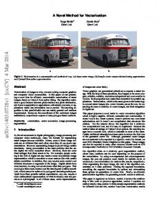
The non-linear fluxguide behaviour of the shield is most effective in the high permeability (no saturation) region of the material characteristic, but with a bias added, the operating point is pushed to an area of low permeability (high saturation) by the summation of the permanent magnet DC field and transmitter AC field (Fig 1). The initial operating point of the shield (due to the transmitter flux, Htx) is thus moved into the low saturation region by appropriate calibration of the DC magnets on the receiver system (Htx + Hpm). The material BH characteristic has to be canted enough so as to be able to contain the Tx generated flux field without saturating, but have a knee point acute enough such that the DC threshold flux can switch it into a region of high saturation very quickly. Using a highly directional array of magnets makes this mechanism very region specific, and hence only portions of the flux guide are saturated at any time. Fig. 2 shows how one
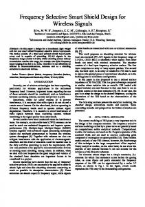
The experimental setup consisted of incorporating two different types of 0.5 mm thick shielding/flux guides magnetic materials (fractured ferrite (TDK FlexieldTM IBF20) and TDK FlexieldTM IRJ09) above the transmission coil. Their nonlinear properties were selected to both be adequate enough to shield the primary flux when not needed, but their non-linearity was acute enough to switch into saturation and lose its shielding properties when the threshold DC bias field was introduced. Multimeter systems were connected to both the Tx and Rx systems, to measure the input power and output power respectively, with and without the threshold bias magnets. Fig. 3 shows the arrangement of the Rx relative to the Tx side, with an arbitrary separation of 3.5mm between both systems maintained throughout the experiment. The Tx system consisted of a rectangular (100 x 57 mm2) double coil of 13 turns each, made of 162 strand 0.1 mm Litz wire. Its shield was a 140 x 90 mm2 ferrite pad. The system was attached to a current driven source which held the Tx current at 1A throughout the measurements. The operating frequency was held constant at 110 kHz.
3
Fig. 3: Experimental setup for tests, showing Rx and Tx systems, with a 3.5mm air gap between them.
The Rx system consisted of a rectangular (41 x 26 mm2) single coil with 0.43 mm coil diameter. A 0.1 mm thick shield completes the Rx setup. A 3.5 mm air gap surface separates both systems, as the system being investigated was a tightly coupled system. The Tx system had control electronics for waveform rectification, voltage bus control and reactance compensation subsystems attached to it. A shunt resistance of 28 Ohms was used for current calculation and feedback into the Rx sub-systems. In order to create a spatial mapping of the output power from the Tx system, the Rx setup was attached to an XY surface mapping mechanism which moved it in the same plane by 1 mm shifts. Hence the surface induced voltage output of the Rx coil in the plane z = 3.5 mm was measured with a 40 x 40 mm surface with the centre of the Tx coil being the reference axis.. The induced voltage output for four different DC magnet arrays were also measured in order to also investigate the influence of magnet placement on the power transfer efficiency of the system, and obtain the best configuration to provide the biggest ‘flux window’. NdFeB permanent magnets were used in different arrangements. A series of tests were then performed with the configuration as described above, changing the magnet configuration and also alternating between the two shielding materials chosen for this study.
IV. RESULTS AND DISCUSSION Four NdFeB magnet arrangements were investigated, using the test arrangements previously described. For each of these magnet configurations using different size and arrangement of magnets, a surface map of measured induced voltages in the Rx system was obtained. Fig. 4 shows this surface mapping.
Fig. 4: Induced voltage surface map at z=3.5mm measured by the Rx circuit using: a) one magnet , b) two magnets c) four magnets d) six magnets
From Fig. 4, the following quantitative observations can be drawn, which were confirmed by additional repetitive experimentation with more DC array combinations: i. The presence of the magnet increased the power output in the vicinity into which it was introduced. ii. A circular array of smaller magnets produced a region of higher power output hence greater system efficiency, than using larger magnets of the same combined strength. iii. The drop in induced voltage across the surface map (85% in Fig. 4.d, from centre to edge) over just 20 mm from the centre confirms how the magnet array saturates only the local required region of the Tx pad for effective flux transfer. The next set of results give a quantitative snapshot of what efficiencies were possible with this method of flux delivery and control. Table 1 contains the power efficiencies achieved with the magnet configuration shown in Fig. 4.d. In this part of the tests, the efficiencies of power transfer were calculated at the point of highest power output (middle of the magnets) as: Power output from Rx (1) Efficiency = × 100 Power input in Tx It should be noted here that this formulation for efficiency takes into account the efficiency of the whole system, including the control electronics of both sides, and not only analyses the coil to coil power transfer efficiency , as is sometimes done in the industry. Table 1 shows the comparison of these efficiency calculations for both flux guide materials used in the study.
4 REFERENCES [1]
[2] [3]
[4]
[5]
The table shows that using the Flexible ferrite shield material (TDK Flexield IRJ09), the transferred power efficiency goes up to 82% compared with a 14% when there is no threshold biasing DC. This result proves the mechanism of opening a ‘flux window’ by the remarkable increase in efficiency due to introducing the threshold bias field. Furthermore, without the bias threshold field, both shield-types effectively shield the Tx flux, letting practically identical amounts of flux through to the Rx (14.5 % efficiency , meaning less indiscriminate flux escaping from the Tx subsystem). But the more specialized commercial material is proven to possess better material properties for use in such a system, over the fractured ferrite which is also used in the industry for shielding and flux guidance purposes. This dual functionality of the flux guide/shield, in achieving special freedom and flux direction makes this a novel idea in the area of inductive power transfer and delivery, offering more efficient and safe power transfer.
V. CONCLUSION The study showed that by using the appropriate electromagnetic shield material, the induced power efficiency increases from 14% to 82% when there is an appropriate DC bias introduced in conjunction with the receiver system. Furthermore the ‘flux window’ which is achieved by this DC bias, can be opened up in a controllable and regionalized manner using a permanent magnet or an array of magnets. This regional saturation leaves the rest of the transmission pad flux guide in its high permeability state, acting as a flux shield and limiting magnetic field broadcast. Thus the shielding material successfully acts in shielding the flux when it is not needed; the biasing magnet helps move the operation point for the shield, transforming it into a flux window at the particular spatial location by quickly saturating the region on which it is placed. This fast and efficient shield switching enables a system to minimise two challenges experienced in the industry, while still maintaining good efficiency.
[6]
G. M. Budhia,; G.A. Covic; J.T. Boys, “Design and Optimization of Magnetic Structures for Lumped Inductive Power Transfer Systems” , IEEE ECCE pg. 2081 – 2088, 2009. M. Zhixin, F. Aming, Q. Haihong, P. Pingyan, ICECE 2010 , Pg. 562, 2010. E. Waffenschmidt, T. Staring, “Limitations Of Inductive Power Transfer For Consumer Applications”, 13th EPE, Pg 1, 2009. K. Fotopoulou, B. Flynn, “Wireless Power Transfer in Loosely Coupled Links: Coil Misalignment Model” IEEE Trans. Mag. vol. 47, pg. 416-430, February. 2011. Wenzhen Fu, Bo Zhang, Dongyuan Qiu, Wei Wang “Analysis Of Transmission Mechanism And Efficiency Of Resonance Coupling Wireless Energy Transfer System”,IEEE ICEMS, pg. 2163–2168, October 2008. B. L. Cannon, James F. Hoburg, Daniel D. Stancil, Seth Copen Goldstein, “Magnetic Resonant Coupling As A Potential Means For Wireless Power Transfer To Multiple Small Receivers” IEEE Trans. Mag.,vol. 24, pg. 1819-1825, July 2009.