P2P technology has so far only received a doubtful reputation due to its use in file sharing ap- .... Default Tests: Each test module has to provide a list including all tests that will ... e.g., includes tests dealing with different kinds of IP configuration. ..... 1200. 100. 150. 200. 250. 300. 350. Overlay size. Average search time [ms].
University of W¨urzburg Institute of Computer Science Research Report Series
A P2P-based Framework for Distributed Network Management Andreas Binzenh¨ofer, Kurt Tutschku, Bj¨orn auf dem Graben1 and Markus Fiedler, Patrik Carlsson2 Report No. 351
January 2005
1
Department of Distributed Systems Institute of Computer Science University of W¨urzburg, Am Hubland, 97074 W¨urzburg, Germany {binzenhoefer, tutschku, adgraben}@informatik.uni-wuerzburg.de 2
Dept. of Telecommunication Systems School of Engineering Blekinge Institute of Technology 371 79 Karlskrona, Sweden {markus.fiedler, patrik.carlsson}@bth.se
A P2P-based Framework for Distributed Network Management Andreas Binzenh¨ofer, Kurt Tutschku, Bj¨orn auf dem Graben Department of Distributed Systems Institute of Computer Science University of W¨urzburg, Am Hubland, 97074 W¨urzburg, Germany {binzenhoefer, tutschku, adgraben}@informatik.uni-wuerzburg.de
Markus Fiedler, Patrik Carlsson Dept. of Telecommunication Systems School of Engineering Blekinge Institute of Technology 371 79 Karlskrona, Sweden {markus.fiedler, patrik.carlsson}@bth.se
Abstract In this paper we present a novel framework supporting distributed network management using a self-organizing peer-to-peer overlay network. The overlay consists of several Distributed Network Agents which can perform distributed tests and distributed monitoring for fault and performance management. In that way, the concept is able to overcome disadvantages that come along with a central management unit like scalability and reliability. The self-organization of the overlay is achieved by the application of a Distributed Hash Table (DHT) based on the Kademlia algorithm. The DHT mechanism implements a distributed index for the rapid localization of other agents or resources. The framework provides a reliable and scalable basis for distributed tests, like e.g. the identification of performance degradation in IP networks using throughput statistics. The framework is not intended to replace the central network manager, but rather to support it in testing and surveying the status of the corresponding network.
1 Introduction A peer-to-peer (P2P) system is a highly distributed application architecture. A P2P network can be described as a group of entities, denoted as peers, with a common interest, that build a self-organizing overlay network on top of a mixture of already existing networks. Unfortunately, P2P technology has so far only received a doubtful reputation due to its use in file sharing applications. P2P algorithms, however, might be highly helpful in implementing novel distributed, self-structuring network management concepts. In this work we suggest the application of a current generation, structured P2P overlay network for fault and performance management with the aim of enhancing conventional management functions. In general the goal of Network Management is “to ensure that the users of a network receive the information technology services with the quality that they expect” [1]. However, monitoring and provisioning of that quality in an end-to-end manner as perceived by a user [2] is rarely achieved. The OSI-defined Network Management functions (Fault, Configuration, Accounting, Performance, and Security management, FCAPS, cf. [3]) are mostly carried out by rather centralized entities (Network Management Systems) and only in those parts of the network a provider is responsible for. Coordination of the monitoring among different administrative domains is rarely achieved, which also affects possibilities to locate faults and to evaluate end-to-end QoS.
A central fault testing and QoS monitoring architecture typically results in additional, complex entities at the provider. The operator has to ensure the reliability of the entities and assess their scalability. The systems have to scale with O(N 2 ) due to the N (N − 1) potential relationships among N end systems. In addition, relaying monitoring data consumes bandwidth, delays its availability, and might get lost in case of a network failure. A decentralized QoS monitoring, as for example, located on the users end system, might avoid these disadvantages. The use of a distributed, self-organizing software will reduce capital and operational expenditures (CAPEX and OPEX) of the operator since fewer entities have to be installed and operated. Scalability can be achieved by re-using resident resources in conjunction with local decisions and transmission of less data. We propose a new, distributed, self-organizing, generic testing and QoS monitoring architecture for IP networks. The architecture will complement todays solutions for central configuration and fault management such as HP OpenView [4], IBM Tivoli [5] or InfoSim StableNet [6]. The architecture is based on equal agents, denoted as Distributed Network Agents (DNA), which form a management overlay for the service. In this context the word agent is not to be understood as an agent as used by the Artificial Intelligence community, but rather as a piece of software running on different peers, like, e.g., an SNMP-Agent. The self-organization of the overlay is achieved by a P2P-based Distributed Hash Table (DHT), such as Kademlia [7] or Chord [8]. The DHT mechanism implements a distributed index for the rapid locating of other agents or resources. The suggested architecture facilitates the autonomic communication concept [9] by locally determining the perceived QoS of the user from distributed measurements and by exploiting the self-organization capabilities of the DHT for structuring the overlay. It will be able to communicate with standard-NMS via well-established interfaces. Thus, it can be seen as a QoS-enabling complement of existing Network Management solutions. The remainder of the paper is structured as follows: Section 2 introduces the architecture of a DNA and shows how the framework can be used for local and distributed tests. In Section 3 we give an overview of the current P2P generation and motivate why we chose Kademlia as the basis of the DNA overlay. Some details about the implementation of our prototype will be given in Section 4. The functionality of the DNA is validated by simulation in Section 5. Section 6 finally concludes the paper and summarizes our future work.
2 The DNA Framework The DNA framework represents an independent distributed application intended to support the central network monitoring station. In general a central monitoring entity has three major disadvantages: • It is a single point of failure. Once the single central monitoring unit fails, the network will lose its control entity and will be without surveillance. The same problem could, e.g., be caused by a distributed denial of service attack. That is, the functionality of the entire network management depends on the functionality of a single central unit. • It does not scale. On the one hand the number of hosts that can be monitored at a given time is limited by the bandwidth and the processing power of the central monitoring unit.
On the other hand there is a growing number of services that has to be monitored on each host due to the diversity of services that emerge during the evolution of the Internet. • It has a limited view of the network. While a central network manager is able to monitor, e.g., client A and Server B, it has no means of knowing the current status of the connection between the two monitored devices themselves. How the DNA application is able to solve all these problems is summarized in this section. It is also able to support the central unit in two ways. Firstly, the DNAs constantly monitor the network in a distributed way and send a message back to the central server in case the condition for some trigger event is met, similar to SNMP traps. Secondly the central server can query the current state of the DNA on demand. In case the central server fails, the DNA will still be functional and can store the gathered information until the central server goes back online again. First ideas have been discussed briefly at [10]. In this paper we describe our distributed framework in detail (cf. Section 2.1) and present examples for local as well as for distributed tests (cf. Sections 2.2 and 2.3). To provide the different DNAs the possibility to communicate with each other, they build an overlay network. How this overlay is set up is described in Section 3. 2.1 The Basic Concept The Distributed Network Agent (DNA) is based on a modular concept shown in Figure 1. The main component of the DNA, the so-called Mediator, runs as a daemon in the background and is responsible for the communication between the user and the individual test modules. The user is able to connect to the Mediator using the graphical user interface (GUI) or the command line. He can manually start tests or read the results of tests that have already been performed. The tests themselves are arranged in different modules that are not part of the basic DNA architecture. That is, test modules consist of several tests that are similar in respect of their functionality. They represent the functionality of the DNA and can be added or removed without any influence on the operability of the DNA architecture. Figure 1 summarizes the design of the DNA framework. The Mediator either receives a test request from the user or autonomically schedules a test itself. It then performs the corresponding test using the provided Interfaces and finally sends the results to the GUI upon request. The individual tests are executed by the Mediator using the Interface component. Therefore, any test module that implements all features required by the Interface component can be added to the DNA framework. A description of the two most important features required by the Interface component and their purpose is given in the following: • Default Tests: Each test module has to provide a list including all tests that will be run when the module is called by the Mediator without any parameters. This list of default tests will be executed when the user did not specify any details. Advanced users, however, are able to choose another subset of tests from the module that is adapted to their specific needs. The default test sequence offers the possibility to implement a test module that, e.g., includes tests dealing with different kinds of IP configuration. In this example the default test sequence could cover all properties of a static IP, while support for DHCP might be optional.
DNA Mediator
GUI
Interfaces
Module 1
Module 2
…
Figure 1: The modular framework of the DNA • Test Dependencies: If not specified otherwise all selected tests of a test module are performed in parallel. However, the DNA offers the possibility to use test dependencies. That is, a test module can provide a list containing the dependencies of its individual tests. The Mediator does not start a test until all its dependencies were performed successfully. The following two tests provide a simple example for test dependencies: A test that checks the state of a network interface card (NIC) and a second test that pings a predefined host using the same NIC. Obviously the second test is dependent on the first one, since it can only succeed if the NIC is up and running. The Mediator would therefore only execute the second test if the first test already finished successfully. Any test module that offers a list of Default Tests and Test Dependencies can be added to a running DNA at any time. Since a great fraction of network problems are actually caused by local errors like misconfiguration and software failures, we outline a test module containing local tests in the following section. Before a DNA takes part in the DNA overlay, it can run the local test module to eliminate any possibility of local errors. 2.2 Local Tests In this section we briefly describe a test module containing local tests, which is an inherent part of our prototype discussed in Section 4. First, we summarizes the set of default tests and give a brief description of the remaining tests in the module afterwards. All local tests are bound to a specific network interface card, which can be selected by the user. 2.2.1 Default Test Sequence The default test sequence contains eight tests, which can be divided into “Hardware and TCP/IP” and “Local configuration and network connectivity”. The five tests in the latter category all depend on the three tests dealing with hardware and TCP/IP.
Hardware and TCP/IP • NICStatus: This test returns information about the network interface card and its current state, including a driver check and the like. It is mainly used to eliminate the possibility of hardware failures or problems with the driver. • NetConnectionStatus: This test is used to check the current connection status of the NIC. Causes for an error include a cable that is not plugged in, or a network interface card still running an authentication process. • PingLocalHost: The functionality of the TCP/IP stack is validated by sending a ping request to the loopback address (127.0.0.1). In case all three tests finish successfully, the Mediator will call the remaining five tests of the default test sequence. Local configuration and network connectivity • IPConfiguration: This test verifies that a valid IP address is assigned to the NIC. It also checks if the associated gateway is on the same subnet as the IP address. • DNSConfiguration: The test verifies that at least one DNS server is assigned and can be reached by a ping request. If the ping message failed whereas the lookup was successful, only a warning message is reported, as some DNS servers might not respond to ICMP packets. Furthermore, the functionality of the DNS server is tested performing a predefined DNS lookup and optionally a reverse lookup. • DHCPLease: In case of using DHCP on a machine running Windows, the IP address is checked to ensure that the network interface card is not set up to use a so called Autonomic Private IP Address (APIPA). This might occur, if the server has no more capacities to provide a new IP address or if the user participates in an encrypted wireless LAN (e.g. WEP) using an invalid key. • PingOwnIP: To exclude a communication problem between the operating system and the NIC, the IP address assigned to the adapter is pinged. • PingWellKnownHosts: This tests sends a ping request to a list of predefined well known hosts. If a specified number of hosts in this list does not respond in time, the test returns an error. 2.2.2 Additional Local Tests In this section we give an example of additional tests that are not in the default test sequence of the corresponding test module. The following three tests belong to our local test module but are not part of the default test sequence, since they are specific to the Windows OS. Advanced users can include the tests in case the DNA is running on a Windows based platform.
• EventViewer: The test searches in the ”Event Viewer Log” for error events caused by TCP/IP or DHCP. If the Windows event viewer has recorded problems with respect to TCP/IP or DHCP those errors will be forwarded to the GUI of the DNA. • HostsAndLmHosts: Before Windows uses DNS or WINS it tries to resolve a domain name using the HOSTS or LMHOSTS file. If one of these files contains a wrong entry the resolution of the corresponding name fails. The test searches for syntax errors in both files and sends ping requests to valid entries. • RoutingTable: The Windows routing table is divided into a dynamic and a persistent part. This test pings the gateways of both tables and reports an error message, if one of them is not reachable. 2.3 Distributed Tests In this section we describe how to use the DNA framework to implement distributed test modules. A distributed test is a test that is performed in conjunction with at least one other DNA. To be able to communicate with each other the DNAs build an overlay network on top of the monitored network. To perform a distributed test a DNA can then either connect to a randomly chosen DNA or to a specific DNA chosen by the user. Section 3 describes the P2P based DNA overlay in detail. The following two distributed tests point out the possibilities of the distributed DNA framework that arise by extending a simple local test to a distributed test: • PingWellKnownHosts: If a single DNA or a central network manager does not receive a ping reply from a well known host, either the host or any link on the path to this host could be down. Using the DNA framework, however, a DNA can ask another DNA to ping the same host and evaluate the returned result. In case another DNA is able to ping this host, the possibility that this host is down can be ruled out and the cause of the error can be narrowed down to a network problem between the DNA and the well known host. If the DNA has knowledge about the network topology, which could, e.g., be gained using network tomography, the distributed ping test can also be used to pinpoint the broken link or to locate a bottleneck by comparing the delay of the ping messages. • DNSProxy: In general a DNA can use another DNA as a temporary proxy or relay host. In case a DNA loses the connection to its DNS server and can thus no longer resolve domain names, it can use another DNA as a DNS proxy. That is, the DNA forwards the DNS query to another DNA, that in turn tries to resolve the domain name using its own DNS server. This way the DNA is able to bridge the time its DNS server does not respond to DNS queries. In a similar way two DNAs with a broken direct connection could use a third DNA, that still has a connection to both DNAs, as a temporary relay host. As stated above the DNAs build an overlay network to be able to communicate with each other. They are able to communicate with a random DNA in the overlay or to search for a specific DNA. The following two tests provide examples of how to build distributed applications based on this aspects of the DNA framework:
• PortScan: If a DNA peer is running a webserver or offers some other service that requires an open port it usually is probed by a central network manager to ensure a continuous service. On the one hand this method does not scale with the number of services the central network manager has to monitor, on the other hand the peer running the service has no influence on the time of the next check. Using the DNA framework, however, the peer is able to ask a random DNA to see if it can reach the offered services. This is also a scalable way to monitor a large number of services. The DNAs monitor the services running on their peers in a distributed way and only send a message back to the central network manager in case of an error. • Throughput: Usually it is not easy for a user to verify a service level agreement or to measure the bandwidth to another point in the network. The possibility to search for a specific DNA enables a peer taking part in the DNA overlay network to search for a specific communication partner and ask for a throughput test. A very simple way to do so is to constantly send traffic to the other DNA for a certain period of time and simply measure the average throughput. However, there are more sophisticated ways, which we intend to integrate in future work. The above tests are just some examples of how to use the DNA framework. In future work we intend to present some more advanced test modules for the DNA in detail. In Section 6 we summarize our ideas for a new, distributed passive QoS monitoring concept. The next section discusses general security issues and a way of how to deploy new test modules to the DNA overlay network. 2.4 Deployment of New Tests Considering a running DNA overlay network, one can not assume that all DNAs are always having the same test modules. An obvious way to deploy new test modules is to send the modules on demand. That is, if A asks B to perform a distributed test but B does not have this specific test, A simply sends the test module to B. However, this implies that B implicitly trusts A. A security risk that is obviously not negligible. In fact a framework that allows other machines to run arbitrary code would be the perfect tool for distributed denial of service attacks. One way to solve this problem is to only download new test modules from a central trust server. That is, all DNAs trust a central entity and only run code that is signed by this central authority. While this solution is sufficient for small networks it does not scale to larger networks. A scalable implementation of the DNA framework therefore needs a distributed trust model. Since there is an independent research area dealing with security and this paper is mainly intended to be a proof-of-concept for a P2P based framework for network monitoring, we will refrain from addressing security issues. There exist, however, different approaches to build distributed trust models for P2P systems. In [11], e.g., Josephson proposes a scalable method for P2P authentication with a distributed single sign-on service, that could be used as the trust model for our DNA.
3 P2P-based Overlays A P2P overlay network is a virtual network consisting of peers and logical connections that is built on top of an existing network. One of the main features of such an overlay network is the ability of each peer to find any other participating peer in reasonable time independent of the current IP-address or network provider of the searched peer. That is, to search a peer one does not need to know the IP-address of the searched peer, but just something that uniquely identifies this peer. Older P2P algorithms had to rely on a central server [12] or needed too much overhead when searching for other peers [13]. The current generation of structured P2P networks, however, is able to locate other peers using only O(log(n)) messages while keeping connections to only O(log(n)) other peers in an overlay network of size n [14]. In this section we give a short overview of existing structured P2P algorithms and explain our choice for one of them. 3.1 Distributed Hash Tables and Kademlia P2P systems like Chord [8], CAN [15], Pastry [16] and Kademlia [7] implement so called Distributed Hash Tables (DHT) to organize their overlay network. A DHT assigns each peer wanting to participate in the overlay an m-bit identifier using a hash function such as SHA-1 [17] or MD5 [18]. Additionally each document that is to be stored in the peer-to-peer network is assigned an m-bit identifier using the same hash function. Based on these ids the underlying P2P mechanism decides where to store the documents. That is, the P2P algorithm determines which peers are going to be responsible for which documents. Peers searching for particular documents will then use the same algorithm to retrieve the searched information from the P2P overlay network. Chord, e.g., places the participating peers on a ring structure, while each peer keeps pointers to its direct neighbors on the ring. CAN uses a virtual d-dimensional Cartesian coordinate space on a d-torus and a zone based routing algorithm. In Pastry each peer has a neighborhood set and a leaf set. Routing is based on prefix matching. In this section we present the Kademlia algorithm in more detail. Like most other DHTs Kademlia uses 160-bit identifiers as peer ids. The distance between two peers is determined by the XOR metric, that is two peers with identifier x and y have a distance of d(x, y) = x ⊕ y. For each 0 ≤ i ≤ 160, every peer keeps a list of k other peers that are at a distance between 2i and 2i+1 away from itself. Those lists are called k-buckets. We a default value of k = 5. Figure 2 shows exemplary k-buckets for a peer with id = 00000 and k = 2. Note that peer 00000 knows all peers in its direct neighborhood but only a few peers in more distant regions. When searching for other peers or documents, a peer simply sends out search requests to the α (default = 3) closest peers it can find in its k-buckets. In turn, all of the α queried peers respond with the k closest peers they can find in their k-buckets. The searching peer then recursively queries α of the new peers it learned of. A search finally terminates when the searched peer or document is found or if the last recursion step did not return any new peers. The k-buckets are initially filled by searching for a random id in the range of the corresponding bucket. The buckets are then refreshed whenever there is incoming traffic from other peers. Thus, as long as the network produces enough search traffic to keep a peer’s buckets up to date, there is no need for periodic updates. If, however, a bucket has not been refreshed within one
0
1 11111 10101
1
0
01010 01001
1 00111 00110
0 00010 00001
Figure 2: 3-buckets for a peer with id = 0000 hour the peer will manually refresh this bucket. See [7] for a more detailed description of the Kademlia algorithm. In the following section we summarize the main reasons why we have chosen a modified Kademlia to form the DNA overlay network. 3.2 The DNA Overlay To be able to search for other peers, the individual DNAs build an overlay network. The main purpose of this overlay is to keep the DNAs connected in one logical network and to enable a single DNA to find another DNA in reasonable time. In principle, we could use any of the above mentioned DHT algorithms, however, there are a number of reasons why we chose the Kademlia algorithm as the basis of the DNA overlay. Kademlia offers a set of features that are certainly not unique to it, but that are so far not offered by another single DHT all at once. In detail those features are: 1. Symmetry: Due to the symmetry of the XOR metric d(x, y) = d(y, x), the DNA overlay network is symmetric as well. Thus there is no difference between successors and predecessors, and we can concentrate on a peers neighbors in general. 2. Unidirectionality: Like Chord, the Kademlia overlay network is unidirectional. That is, for any identifier x and an arbitrary distance s > 0 there is exactly one point y such that d(x, y) = s. Thus, independent of the originating peer, lookups for the same peer will all converge along the same path. 3. Parallel queries: One of the most advantageous features is the possibility to send out parallel queries for the same key to different peers. This way, timeouts on one path do not necessarily delay the search process, guaranteeing faster and more reliable searches under high churn1 rates. 1
The rate at which peers join and leave the overlay network
4. Bucket entries: The freedom to choose arbitrary peers that fall into the range of a bucket as entries of this bucket creates a greater flexibility for the user. In the original paper [7] peers were chosen by the time of last contact to obtain more reliable bucket entries. Bucket entries, however, can be chosen by any criterion like trustability or reliability. The best known approach is to chose peers according to their ping times to guarantee low latency paths when searching. 5. Low periodic traffic: In contrast to most other DHTs Kademlia uses almost no periodic overhead traffic but exploits the search traffic to stabilize the overlay network connections. Bucket refreshes are not done until the search traffic drops to a minimum. Configuration information spreads automatically as a side-effect of key lookups. 6. Security: As a result of its decentralized nature Kademlia is resistant against certain denial of service attacks. This security against attackers can even be improved by banning misbehaving peers from the peers buckets. At present there exist numerous extensions for most other DHTs that provide the features mentioned above or even introduce new features not yet offered by Kademlia. Chord, e.g., has been extended to support symmetric searches [19] and to consider physical proximity when choosing neighbors [20]. Our choice of Kademlia was basically motivated by the fact that all needed advantages already come with the simple basic version. We still applied some minor modifications to adapt the original algorithm to meet our needs. The biggest difference is that we entirely do without documents. That is, as compared to the original Kademlia, the DNA overlay does not store any kind of documents. While document management can easily be included at a later point in time without losing any of the above advantages, there was simply no need to support documents in the current DNA prototype. This decision is further motivated by the fact that the DNAs only need to be able to search for other DNAs and not for documents. We introduce an easier way of searching for other peers. In general, a peer can be searched using its hash id. Usually a peer obtains this id by hashing its IP-address. However, this is just one way of generating a peers unique random identifier. In fact in the original Kademlia publication it is left to the reader how to choose identifiers for the participating peers. To enable searches for other peers, we therefore simply hash a unique property of the peer, e.g. the email-address, a unique nickname or even the MAC-address. Other peers are then able to search for a specific peer using the hash value of this unique property of the searched peer as a search criterion. We applied another minor change to enable a fast search for random communication partners. Usually a search stops when the searched peer is found. When searching for a random peer, however, we simply start a search for a randomly chosen id from the identifier space and take the closest peer returned by the search. Obviously the DNA cannot know if the next search step is going to return some even closer peers. The only way to complete this kind of search is to wait for the answer of all actively queried peers, which could slow down the search. A peer therefore calculates the distance to its own neighbors using its closest k-bucket and stops the search for a random peer as soon as the returned peers have approximately the same distance to the randomly chosen id. This way the search for a random peer converges more quickly. In Section 5 we discuss the results obtained from our simulator in detail.
4 The DNA Prototype As a proof of concept and practicability of our work, we implemented a prototype of the DNA. The general concept is platform independent. Most clients, however, are running MS Windows as an operating system. We therefore decided to implement a Windows based prototype. The implementation was done in .NET, as the WMI Interface offers the opportunity to access all kind of information about the local system state as well as the state of the network in very few lines of code. Thus, we were able to include all local tests described in Section 2 as well as a distributed ping test, a simple bandwidth measurement tool and a temporary DNS proxy. Furthermore, using the .NET Remoting functionality we are also able to exchange test modules in the form of signed assemblies and to run tests on distant DNAs. The DNA prototype was implemented within the scope of an industrial cooperation with Datev, one of the largest information service providers and software firms in Germany as well as Europe. This provided us the opportunity to proof the functionality of the concept by successfully running the DNA in a realistic testbed with over 50 machines. One of the main advantages besides those mentioned in the previous sections turned out to be the plug and play character of the DNA framework. Due to the DHT based overlay network the DNA framework is selfconfiguring. To include a new DNA into the existing overlay, the user just has to start the client and it will automatically find its position in the overlay network. On the other hand, if a client fails, the overlay network proved to be self-healing by automatically updating the neighborpointers needed to keep the overlay network stable. However, to prove the scalability of the prototype and to analyze the influence of high churn rates on its stability, we also implemented a simulator in .NET, which is based on the code of the prototype. The results of the simulations are presented in the next section.
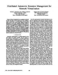
5 Simulation Results In this section we want to prove the functionality and the scalability of our DNA prototype by simulation. The simulator is written in .NET, based on the code used for the prototype. The peers in the simulation build a Kademlia-based overlay network as described in Section 3. The network transmission time for one hop was chosen according to an exponential distribution with a mean of 50 ms. The bucket size was set to k = 5. The simulation contains joins, searches and the modified Kademlia protocol. A running system will further improve the stability of the overlay by exploiting the overhead, that is produced performing tests and exchanging test results. If not stated otherwise, we let a number of nodes join the overlay network and begin a churn phase once the overlay has initially stabilized. To generate churn we model the online time of a peer by means of an exponentially distributed random variable. The longer a peer stays online on average, the less churn there is in the overlay network. To make the simulation results credible [21], we produced several simulation runs and calculated the mean as well as the corresponding confidence intervals. To show the scalability of the DNA we regard the time needed to complete a search for other peers in dependence of the overlay size. First, we regard a system without any churn to validate the claim that the search time in Kademlia based overlays indeed scales. That is, we let n DNAs join the system, wait until the overlay network stabilizes and then let a number of random DNAs
Average search time [ms]
350
300
60 minutes online time 250
200
No Churn
150
100
0
200
400
600
800
1000
1200
Overlay size
Figure 3: Duration of a search in dependence of the size of the overlay search for other peers. The concave curves in Figure 3 show that the search in our prototype does indeed scale. In a network of 1000 peers a search for another DNA takes less than 200 ms. To see the influence of churn on the search time, we repeated the same simulations and set the average online time of a peer to 60 minutes. To keep the size of the overlay constant on average, we chose a corresponding Poisson arrival process to let new DNAs join the network. The results are also shown in Figure 3. Due to timeouts and wrong bucket entries caused by the churn in the system, searches take longer than in the scenario without churn. However, the search algorithm does still scale to larger system and enables fast searches for other peers. In previous studies [22, 23] we showed that the size of the network itself is not the crucial factor in terms of scalability and overlay stability. In fact the robustness of the DHT is mainly influenced by the current churn rate. A good way to prove the stability of the overlay network is therefore to look at the correctness of the entries in a peers k-buckets under churn. In general the functionality of a DHT can be guaranteed, as long as the information about a peers neighborhood is not lost. In case the information about more distant peers is lost, the performance of the overlay might get slightly worse, but the underlying algorithms will still be functional. In Kademlia the neighbors of a peer are the entries of its closest k-bucket. We therefore study the correctness of the closest k-bucket to evaluate the stability of the DNA overlay. We generate a churn phase and create a snapshot within this phase. The actual neighbors of a peer (obtained form the global view offered by the simulation) are compared to the current bucket entries of a peer. In Figure 4 we show how many of its k = 5 direct neighbors a peer actually knows in dependence of the churn rate in the system. On average a peer knows more than 4.5 of its 5 direct neighbors even if the average peer stays online for only 30 minutes. Note that the correctness of a peer’s neighbors does not depend on the size of the network at all. The curve progression is almost identical for 500 and 100 peers. That is, the stability of the overlay network does not depend on the size but on the current churn rate of the system.
Number of known neighbors (max 5)
5 4.95
500 peers
4.9 4.85 4.8 4.75 4.7
100 peers
4.65 4.6 4.55 4.5 20
40
60
80
100
120
140
Average online time [min]
Figure 4: Average number of missing direct neighbors The above results show that the DNA overlay offers scalable search times and is robust against churn. The remaining question is how much bandwidth the DNAs need to maintain the overlay network. In Figures 5 and 6 we show the average amount of Bytes per second a DNA produces while online. Figure 5 plots the average maintenance traffic of a single peer against the total number of peers in the overlay network. Again the lower curve represents a system without any churn. The larger the overlay network gets, the more buckets are maintained and the more traffic is needed to keep these buckets up-to-date. As can be seen in the figure the consumed bandwidth scales very well to the size of the system. The upper curve summarizes the same results for an average online time of 60 minutes. It has a similar progression, but illustrates that a peer uses more maintenance traffic during a churn phase. To study the influence of churn on the bandwidth needed for maintenance in more detail, we did a parameter study for the churn rate in Figure 6. The average online time of a peer varies between 30 and 120 minutes. The shorter a peer stays online on average, i.e. the more churn there is in the system, the more maintenance traffic is produced by the DNA client. That is, the DNA adapts automatically to the current churn rate. The more churn there is in the system, the more maintenance bandwidth a DNA client uses to guarantee the functionality and stability of the overlay network. As stated above, the DNA needs more maintenance traffic in a larger network, as there are more buckets that have to be kept up-to-date.
6 Conclusions and Future Work In this paper we presented a novel technique for distributed fault and performance management. The proposed DNA framework is based on a self-organizing DHT overlay network (Kademlia) and offers plug and play functionality when integrating new DNA clients. The system is able to perform local tests on the client and distributed network tests in conjunction with other DNA
Maintenance traffic [B/s]
35
30
25
60 minutes online time
20
15
No Churn 10
5
0
200
400
600
800
1000
1200
Overlay size
Figure 5: Average maintenance traffic in dependence of the system size clients. As a proof-of-concept, we built a running prototype and in addition proved its scalability by simulation. We investigated the robustness and reliability of the DNA in terms of churn behavior, i.e. the fluctuation of the size of the overlay network. A local test module, as well as examples for distributed tests were described in detail. The proposed distributed end-toend architecture facilitates the provisioning and monitoring of new services offered by service providers. Future work will be devoted to the integration of a new passive end-to-end QoS monitoring concept featuring performance management from the user point of view. This concept relies upon comparisons of bit rate statistics on sender and receiver side [24], on which bottleneck indicators are built. Measuring those statistics on transport layer grants a general applicability for any kind of IP-based communication. In the DNA framework, bottleneck indicators can be determined through distributed tests. The results of such test will be available to standard-network management systems via well-established interfaces, like SNMP traps or MIB variables. Thus, it can be seen as a QoS-enabling complement of existing network performance management solutions. The integration of distributed passive bottleneck indicators into the DNA concept will be a matter of future work.
Acknowledgments The authors would like to thank Phuoc Tran-Gia and Stefan Chevul for the helps and discussions during the course of this work. Additional thanks go to the EuroNGI FP6 network of excellence for supporting this work.
Maintenance traffic [B/s]
40
35
30
500 peers 25
20
15 20
100 peers
40
60
80
100
120
140
Average online time [min]
Figure 6: Average maintenance traffic in dependence of the churn rate
References [1] M. Subramanian, Network Management – Principles and Practice. Addison-Wesley, 2000. [2] M. Fiedler (ed.), “EuroNGI Deliverable D.JRA.6.1.1 – State-of-the-art with regards to user-perceived Quality of Service and quality feedback,” May 2004. URL: http://www.eurongi.org/. [3] ISO/IEC 7498-4:1989, “Information processing systems – Open Systems Interconnection – Basic Reference Model – Part 4: Management framework,” 1989. URL: http://www.iso.org/. [4] HP OpenView Management Software. URL: http://www.openview.hp.com/. [5] IBM Tivoli Software. URL: http://www.ibm.com/tivoli/. [6] InfoSim GmbH & Co. KG. URL: http://www.infosim.net/. [7] P. Maymounkov and D. Mazieres, “Kademlia: A peer-to-peer information system based on the xor metric,” in IPTPS 2002, (MIT Faculty Club, Cambridge, MA, USA), March 2002. [8] I. Stoica, R. Morris, D. Karger, M. F. Kaashoek, and H. Balakrishnan, “Chord: A Scalable Peer-to-peer Lookup Service for Internet Applications,” in ACM SIGCOMM 2001, (San Diego, CA), August 2001. [9] Autonomic Communication (IST FP6 Project). URL: http://www.autonomic-communication.org/.
[10] A. Binzenh¨ofer, K. Tutschku, and B. auf dem Graben, “DNA – A P2P-based Framework for Distributed Network Management,” in Peer-to-Peer-Systeme und -Anwendungen, (GI/ITG Work-In-Progress Workshop in Cooperation with KiVS 2005, Kaiserslautern), March 2005. [11] W. K. Josephson, E. G. Sirer, and F. B. Schneider, “Peer-to-peer authentication with a distributed single sign-on service,” in The 3rd International Workshop on Peer-to-Peer Systems IPTPS’04, (San Diego, USA), February 2004. [12] Emule website, “http://www.emule-project.net.” [13] Gnutella website, “http://www.gnutelliums.com.” [14] J. Xu, A. Kumar, and X. Yu, “On the fundamental tradeoffs between routing table size and network diameter in peer-to-peer networks,” in IEEE Journal on Selected Areas in Communications, vol. 22, January 2004. [15] S. Ratnasamy, P. Francis, M. Handley, R. Karp, and S. Shenker, “A scalable contentaddressable network,” in ACM SIGCOMM 2001, (San Diego, CA, USA), 2001. [16] A. Rowstron and P. Druschel, “Pastry: Scalable, distributed object location and routing for large-scale peer-to-peer systems,” in IFIP/ACM International Conference on Distributed Systems Platforms (Middleware), (Heidelberg, Germany), pp. 329–350, November 2001. [17] FIPS PUB 180-1, “Secure hash standard.” Federal Information Processing Standards Publication 180-1, April 1995. [18] R. Rivest, “RFC 1321 - The MD5 Message-Digest Algorithm,” April 1992. [19] V.Mesaros, B.Carton, and P. Roy, “S-Chord: Using symmetry to improve lookup efficiency in chord,” in International Conference on Parallel and Distributed Processing Techniques and Applications PDPTA’03, (Las Vegas, Nevada), June 2003. [20] K. Gummadi, R. Gummadi, S. Gribble, S. Ratnasamy, S. Shenker, and I. Stoica, “The impact of dht routing geometry on resilience and proximity,” in ACM SIGCOMM 2003, (Karlsruhe, Germany), August 2003. [21] A. M. Law and W. D. Kelton, Simulation Modeling and Analysis. McGraw-Hill Higher Education, 3rd ed., 1999. [22] A. Binzenh¨ofer and P. Tran-Gia, “Delay Analysis of a Chord-based Peer-to-Peer FileSharing System,” in ATNAC 2004, (Sydney, Australia), December 2004. [23] A. Binzenh¨ofer, D. Staehle, and R. Henjes, “On the Stability of Chord-based P2P Systems.” Technical Report No. 347, November 2004.
[24] M. Fiedler, K. Tutschku, P. Carlsson, and A. Nilsson, “Identification of performance degradation in IP networks using throughput statistics,” in Providing Quality of Service in Heterogeneous Environments. Proceedings of the 18th International Teletraffic Congress (ITC18) (J. Charzinski, R. Lehnert, and P. Tran Gia, eds.), (Berlin, Germany), pp. 399–407, September 2003.