Arne A. Nils- son, from North Carolina State ...... Bergman, L.A. and Eng, S.T.,"A Synchronous Fiber Optic Ring Local Area Network for Multigigabit/s Mixed-Traffic ...
A Parallel Approach to Integrated Multi-Gbit/s Communication over Multiwavelength Optical Networks
Adrian Popescu
A Dissertation submitted to the Royal Institute of Technology in partial fulfillment of the requirements for the degree of Doctor of Philosophy
May 1994
TRITA - IT - 9306
The Royal Institute of Technology
ISSN 1103 - 534X
Department of Teleinformatics
ISRN KTH/IT/R -- 93/06 -- SE
Electrum / 204 S - 164 40 Kista Stockholm, Sweden
To the memory of R. P. Singh
A Parallel Approach to Integrated Multi-Gbit/s Communication over Multiwavelength Optical Networks
Abstract
As the diversity and the performance of computational machinery and of communication technologies have dramatically increased, independent of each other, so have the demands on interconnection facilities. The coming of new, distributed, network-based computing paradigms and of new communication services, including multimedia, has posed a stringent need for high capacity, vastly faster and more responsive networking. Today, new multi-Gbit/s optical integrated networks are under development. However, while the Wavelength Division Multiplexing (WDM) technique has further manifoldly increased the transmission capacity on optical fiber, the performance increase of supporting nodal electronics and (software) processing needed for switching, buffering and control purposes has not matched this trend. The performance bottleneck has shifted from the transmission channel to network nodes. The main challenge is therefore to better understand and to exploit, in the most effective way, the properties of optical fibers. How can the properties of optical fibers best be employed to meet the increasing needs of emerging applications with different and conflicting performance requirements? To date, optical networks look essentially like those evolved in the prephotonic era, with optical fiber replacing copper wiring or radio links. For reasons presented in this dissertation, this solution no longer suffices. In order to remove the fundamental bottlenecks in a vertically-oriented communication model (type OSI), new communication models are needed that exploit the network resources in such a way that the performance benefits of using optical fibers can be fully realized, and not be limited by electronics or protocol processing. This dissertation addresses the problems encountered in alleviating the fundamental bottlenecks, and a new architectural solution is advanced to solve these problems. After a brief analysis of the above-mentioned bottlenecks (i.e., electro-optic, service and processing bottlenecks), a new, parallel, horizontallyoriented model is advanced for the communication process in a multi-Gbit/s optical integrated Local Area Network (LAN) environment. Critical evaluation of the basic concepts behind this model is done and a casestudy network architecture is chosen to address the typical research topics, i.e., multiple data stream synchronization and multiaccess and switching mechanisms for isochronous and nonisochronous traffic. For the purposes of our study, an integrated 19.2 Gbit/s LAN environment is considered. A top-down approach is adopted in design, according to which we design and develop the underlying transport entities according to the needs of the specific (traffic) applications. Data rates up to 9.6 Gbit/s are considered, for a variable number of stations, with a variable number of substations connected to each station, and a network throughput of about 20 Gbit/s. Electronic (logic) speeds of 100 Mbit/s and processing speeds up to 20 - 30 MIPS are also taken into consideration. This architectural model is studied in-depth in order to obtain and evaluate the performance measures. Detailed theoretical studies of modeling and performance analysis are conducted. The performance aspects for alternative solutions, possible for diverse network entities, are evaluated with the purpose of investigating the limits and the advantages of this approach. The new model of parallel communication put forth in this dissertation does not follow the standard layering approach of other LANs. Instead, a horizontally-oriented model is advanced for the communication
process to open up all three fundamental bottlenecks. For reasons discussed in the dissertation, a direct extension of the standard, vertically-oriented OSI model to a multigigabit optical network environment may not be suitable. Furthermore, the design follows new concepts in opening up the electro-optic and service bottlenecks. A new WDM architecture is used that is based on the Wavelength-Dedicated-to-Application (WDA) concept. The network has an architecture structured to a multiclass network model with a pipelined model used for communication. A coarse WDM is used to open up the electro-optic bottleneck. Specific time-synchronous channels, placed in different wavelengths, are dedicated to different applications and control mechanisms according to their traffic characteristics, e.g., CBR and/or VBR isochronous traffic, computer data transfer (with focus on latency), application-specific control mechanisms for media access, error handling, flow control, etc. We use separation of different user-traffic, and of information traffic from control traffic, in order to open up the service bottleneck. Furthermore, separate, simplified and application-oriented protocols supporting both packet- and circuit-switching are used to open up the processing bottleneck. An original solution is advanced for the problem of multiple data stream (low-level) synchronization in a WDA network. It includes specific solutions for point-to-point transmission, bit synchronization (jitter compensation) and slot synchronization, as well as proper algorithms for frame synchronization. Detailed theoretical analysis and performance evaluation are provided for the study of typical cases, which include one, or multiple, data channel(s) and one, or multiple, control channel(s), all placed in different wavelengths on the same fiber. Discussion of basic implementation issues is provided as well. In order to provide bounded delay and jitter requirements for loss-free nonisochronous traffic, we suggest a new approach for congestion control and bandwidth allocation, which is of type Rate Controlled Admission with Priority Scheduling Service. We call this Dynamic Time Sharing (DTS). This approach is based on guaranteeing specific traffic parameters (bandwidth requirements) through a policer/shaper unit, and then optimizing the bandwidth assignment, within the network, for specific parameters of interest (such as delay or jitter, and loss). The optimization process is based on the parameters guaranteed by the shaper. A batch admission policy is used at the edges of the network according to a specific framing strategy to follow the traffic (peak bandwidth) characteristics of different traffic subclasses. On the other hand, another framing (congestion control) strategy is used within the network, which is based on different (delay/loss) requirements of the traffic classes. Proper management of bandwidth and buffer resources is provided in every (switch) node of the network, such as to guarantee the diverse performance of interest, regardless of traffic statistics, network size and transmission speed. The performance results clearly indicate the feasibility of this new concept as a candidate for the future multi-gigabit communication over multiwavelength optical networks. Such an architectural model offers the choice of performance restricted by optics, and less by electronics or processing. It offers the choice of reducing the latency in communication to limits that are commensurable with those given by the propagation delay on fiber. Real-time services, with specified delay and bandwidth requirements, can be easily provided. Simple and low-processing application-oriented protocols are used, with no interference among user-traffic classes. It is therefore very suitable for service integration, irrespective of traffic and network conditions. There is no need for technological breakthroughs, no need for wavelength agility, and LAN environments can be easily developed that are capable of supporting large number of supercomputers. The disadvantage of this approach is given mainly by the hardware replication, which is needed in every node for each traffic class.
Key words: OSI, WDM, bottlenecks, latency-limited design, parallel communication, multimedia traffic integration, wavelength-dedicated-to-application, optical fiber transmission, multimedia synchronization, MAC, switching, congestion control, modeling, analysis.
Acknowledgements I would like to express my deep gratitude and appreciation to a number of people for their contributions to this research and for their support and encouragement. First and foremost, I want to mention my late friend, Prof. Raghuvansh P. Singh, whose tragic fate took him from us. His strong belief in me and my ideas was the decisive point that made possible to start this work. His great spirit has always been with me, and will always remain with me. The stimulating teaching and research environment at the former department of Telecommunication and Computer Systems, as well as the new department of Teleinformatics, was the ideal place to do this research. Much credit for this dissertation should go to my advisors, Prof. Anders Hedin and Prof. Björn Pehrson, for their continuous and generous support and guidance. Working with them has been a most rewarding and enjoyable experience for me because of their enthusiasm, helpfulness, and encouragement. Also, Assoc. Prof. Janos Werner and Prof. Lars-Erik Thorelli warmly supported me in the course of this work. Their strong and continuous encouragement, as well as the confidence they placed in me, especially when things were looking down, is greatly acknowledged and appreciated. Special thanks go to Prof. Ian F. Akyildiz from Georgia Technology Institute, Atlanta, and Dr. Ashok Erramilli from Bellcore, Red Bank, for their strong support and generosity with respect to my research. Their insightful and penetrating questions forced me time and again to rethink and better understand the new concepts and algorithms I put forth in this dissertation. I feel especially fortunate to have had such positive professional and personal relationships. I would also like to express my gratitude to the member of my committee, Prof. Arne A. Nilsson, from North Carolina State University, Raleigh. I greatly appreciate his efforts to improve the quality of this research and am thankful for the excellent working relationship that we maintained throughout the final phase of my research. Dr. Henry Sinnreich from MCI, Richardson, and Prof. Bert Lundy from the Naval Postgraduate School, Monterey, have always given me their full support and encouraged me in my efforts to carry out good research work. For this, I thank them very much. I owe a special debt of gratitude to my colleagues and friends, Assoc. Prof. Rassul Ayani, Dr. Yuri Ismailov, MSc. Parag Pruthi, Dr. Hassan Rajaei, Dr. Frank Reichert and MSc. Robert Rönngren, for their generous support, stimulation and fruitful interactions that have directly benefited my research work. My thoughts are also directed to my former teachers and advisors, Prof. Adelaida Mateescu and Prof. Victor Croitoru, from the Polytechnical Institute of Bucharest, Romania, for the decisive impact they had on my academic formation, especially in the course of my first Ph.D. work done in Romania. Finally, I give my greatest thanks to my wife Mioara and my children Alexandru and Mihai, who have stood by me and supported me well beyond a normal call of duty. Without them, life would seem meaningless. Greatest thanks are also given to my mother Silvia who has done so much for me. Although thousands of kilometers away, she never stopped her love and support. This research work was supported by the Royal Institute of Technology, Stockholm.
Table of Contents
Chapter 1:
.
.
.
.
.
.
.
.
.
.
.
.
.
.
.
.
.
.
1
.
.
.
.
.
.
.
.
.
.
.
.
.
.
.
.
.
.
2
.
.
.
.
.
.
.
.
.
.
.
3
.
.
.
.
.
.
.
.
.
.
.
3
1.2.1.1
Monowavelength Optical Networks .
.
.
.
.
.
.
.
.
.
4
1.2.1.2
Multiwavelength Optical Networks .
.
.
.
.
.
.
.
.
.
6
Introduction
1.1
Introduction
.
.
.
.
1.2
Motivation: Three Fundamental Bottlenecks 1.2.1 Electro-Optic Bottleneck
1.2.2 Service Bottleneck
.
.
.
.
.
.
.
.
.
.
.
.
.
.
.
.
.
.
.
.
.
.
.
9
1.2.2.1
Isochronous Traffic .
.
.
.
.
.
.
.
.
.
.
.
.
.
.
9
1.2.2.2
Nonisochronous Traffic
.
.
.
.
.
.
.
.
.
.
.
.
.
10
1.2.2.3
Transport Mechanisms .
.
.
.
.
.
.
.
.
.
.
.
.
.
11
1.2.3 Processing Bottleneck
.
.
.
.
.
.
.
.
.
.
.
.
.
.
.
.
.
12
1.3
Solution Approach
.
.
.
.
.
.
.
.
.
.
.
.
.
.
.
.
.
.
.
.
14
1.4
Related Work .
.
.
.
.
.
.
.
.
.
.
.
.
.
.
.
.
.
.
.
.
.
15
1.5
Thesis Outline
.
.
.
.
.
.
.
.
.
.
.
.
.
.
.
.
.
.
.
.
.
18
1.6
Contributions of the Thesis
.
.
.
.
.
.
.
.
.
.
.
.
.
.
.
.
.
20
1.7
Summary
.
.
.
.
.
.
.
.
.
.
.
.
.
.
.
.
.
21
Integrated Network Model .
.
.
.
.
.
.
.
.
.
.
.
.
.
22
Chapter 2: 2.1
.
.
.
.
.
.
A New Communication Model
.
.
.
.
.
.
.
.
.
.
.
.
.
.
.
.
23
2.1.1 General Requirements .
.
.
.
.
.
.
.
.
.
.
.
.
.
.
.
.
24
.
.
.
.
.
.
.
.
.
.
.
25
2.1.2 Pipelining the Communication Process 2.1.3 Multimedia Traffic Integration
.
2.1.4 A Parallel Communication Model 2.2
Basic Concepts
.
.
.
.
.
.
.
.
.
.
.
.
.
.
.
.
.
31
.
.
.
.
.
.
.
.
.
.
.
.
.
32
.
.
.
.
.
.
.
.
.
.
.
.
.
.
.
.
.
34
2.2.1 The Separation Principle
.
.
.
.
.
.
.
.
.
.
.
.
.
.
.
.
35
2.2.1.1
Separation of Application Traffic .
.
.
.
.
.
.
.
.
.
.
35
2.2.1.2
Separation of Data Traffic from Control Traffic .
.
.
.
.
.
37
2.2.2 The Wavelength-Dedicated-to-Application Principle 2.2.3 The Synchronization Principle
.
.
.
.
.
.
.
.
38
.
.
.
.
.
.
.
.
.
.
.
41
2.2.4 The Principle of Performance Optimization
.
.
.
.
.
.
.
.
.
.
43
.
.
.
.
.
.
.
.
.
.
44
2.2.4.1
.
.
Application-Oriented Topologies
2.3
2.2.4.2
Resource Management
.
.
.
.
.
.
.
45
2.2.4.3
Application-Oriented Transport and Switching
.
.
.
.
.
.
47
2.2.4.4
Application-Oriented Multiaccess Mechanisms
.
.
.
.
.
.
50
2.2.4.5
Transport Protocols
.
.
.
.
.
.
.
.
.
.
.
.
.
.
.
.
.
.
.
52
.
.
.
.
.
.
.
.
.
.
.
.
.
.
55
A Case-Study Network Architecture. .
.
.
.
.
.
.
.
.
.
56
Summary
Chapter 3:
.
.
.
.
.
.
.
.
.
3.1
Design Goals .
.
.
.
.
.
.
.
.
.
.
.
.
.
.
.
.
.
.
.
.
57
3.2
Design Alternatives .
.
.
.
.
.
.
.
.
.
.
.
.
.
.
.
.
.
.
.
58
3.3
Network Architecture
.
.
.
.
.
.
.
.
.
.
.
.
.
.
.
.
.
.
.
60
3.4
Network Configuration .
.
.
.
.
.
.
.
.
.
.
.
.
.
.
.
.
.
.
70
3.5
Switching Architecture .
.
.
.
.
.
.
.
.
.
.
.
.
.
.
.
.
.
.
76
3.6
Performance Issues .
.
.
.
.
.
.
.
.
.
.
.
.
.
.
.
.
.
.
79
3.6.1 Wide Diversity of Application Requirements .
.
.
.
.
.
.
.
.
.
79
3.6.2 Real-Time Communication Services .
.
.
.
.
.
.
.
.
.
.
.
.
82
3.6.3 Subclasses of Traffic .
.
.
.
.
.
.
.
.
.
.
.
.
.
.
.
.
.
83
3.7
Traffic Policing
3.8
Summary
Chapter 4:
.
.
.
.
.
.
.
.
.
.
.
.
.
.
.
.
.
.
.
.
.
.
.
.
85
.
.
.
.
.
.
.
.
.
.
.
.
.
.
.
.
.
.
.
.
.
91
Multiple Data Stream Synchronization. .
.
.
.
.
.
.
.
.
92
.
.
4.1
Introduction
.
.
.
.
.
.
.
.
.
.
.
.
.
.
.
.
.
.
.
93
4.2
General Requirements .
.
.
.
.
.
.
.
.
.
.
.
.
.
.
.
.
.
.
94
4.3
Quantum Limit
.
.
.
.
.
.
.
.
.
.
.
.
.
.
.
.
.
.
.
.
.
94
4.4
Sources of Errors .
.
.
.
.
.
.
.
.
.
.
.
.
.
.
.
.
.
.
.
.
98
4.5
Point-to-Point Transmission
.
.
.
.
.
.
.
.
.
.
.
.
.
.
.
.
. 101
4.5.1 Optical Sources
4.6
.
.
.
.
.
.
.
.
.
.
.
.
.
.
.
.
.
.
.
.
.
. 102
4.5.2 Optical Receivers .
.
.
.
.
.
.
.
.
.
.
.
.
.
.
.
.
.
. 103
4.5.3 Channel Configuration .
.
.
.
.
.
.
.
.
.
.
.
.
.
.
.
. 104
4.5.4 Errors Due to Additive Noise .
.
.
.
.
.
.
.
.
.
.
.
.
.
. 107
4.5.5 Penalties Due to Dispersion
.
.
.
.
.
.
.
.
.
.
.
.
.
.
. 110
4.5.6 Transmission Limitations .
.
.
.
.
.
.
.
.
.
.
.
.
.
.
. 112
4.5.7 A Sample Design .
.
.
.
.
.
.
.
.
.
.
.
.
.
.
.
.
.
. 113
Bit Synchronization .
.
.
.
.
.
.
.
.
.
.
.
.
.
.
.
.
.
.
. 114
4.6.1 Jitter Components
.
.
.
.
.
.
.
.
.
.
.
.
.
.
.
.
.
. 115
4.6.2 Jitter Constraints .
.
.
.
.
.
.
.
.
.
.
.
.
.
.
.
.
.
. 115
4.6.3 Synchronization Methods .
.
.
.
.
.
.
.
.
.
.
.
.
.
.
. 117
4.6.4 Solution Approach
.
.
.
.
.
.
.
.
.
.
.
.
.
.
.
.
.
. 118
4.6.5 Clock Recovery
.
.
.
.
.
.
.
.
.
.
.
.
.
.
.
.
.
. 122
.
.
.
.
.
.
. 125
.
4.6.6 Penalties Due to Jitter and Static Phase Deviations
4.7
Slot Synchronization
4.8
.
.
.
.
.
.
.
.
.
.
.
.
.
.
.
.
.
.
. 130
Frame Synchronization
.
.
.
.
.
.
.
.
.
.
.
.
.
.
.
.
.
. 134
4.8.1 Solution Approach
.
.
.
.
.
.
.
.
.
.
.
.
.
.
.
.
.
. 135
.
.
.
.
.
.
.
.
.
.
.
.
.
. 138
4.8.3 Frame Synchronization Algorithms .
.
.
.
.
.
.
.
.
.
.
.
. 142
4.8.4 Synchronization Performances
.
.
.
.
.
.
.
.
.
.
.
.
.
. 145
Summary
.
.
.
.
.
.
.
.
.
.
.
.
.
.
. 148
Multiaccess Mechanisms.
.
.
.
.
.
.
.
.
.
.
.
.
.
. 149
.
.
4.8.2 Frame Delimitation Moments
4.9
Chapter 5:
.
.
.
.
.
.
.
.
.
.
.
.
.
.
5.1
Introduction
.
.
.
.
.
.
.
.
.
.
.
.
. 150
5.2
Media Access Protocols for Isochronous Traffic
.
.
.
.
.
.
.
.
.
.
. 151
5.2.1 Performance Modeling .
.
.
.
.
.
.
.
.
.
.
.
.
.
.
.
.
. 152
5.2.1.1
Model Description
.
.
.
.
.
.
.
.
.
.
.
.
.
.
. 152
5.2.1.2
Iso MAC Protocol
.
.
.
.
.
.
.
.
.
.
.
.
.
.
. 154
5.2.1.3
Station Modeling
.
.
.
.
.
.
.
.
.
.
.
.
.
.
. 159
5.2.1.4
Iso MAC Algorithms
.
.
.
.
.
.
.
.
.
.
.
.
.
. 161
5.2.1.5
Resource Partitioning
.
.
.
.
.
.
.
.
.
.
.
.
.
. 166
5.2.1.6
Performance Metrics
.
.
.
.
.
.
.
.
.
.
.
.
.
. 172
5.2.2 Performance Evaluation
.
.
.
.
.
.
.
.
.
.
.
.
.
.
.
. 178
5.2.2.1
Test Conditions
.
.
.
.
.
.
.
.
.
.
.
.
.
.
.
. 178
5.2.2.2
Setup Delay
.
.
.
.
.
.
.
.
.
.
.
.
.
.
.
. 179
5.2.2.3
Blocking Probability .
.
.
.
.
.
.
.
.
.
.
.
.
.
. 181
5.2.2.4
Expected Number of Blocked Calls .
.
.
.
.
.
.
.
.
. 183
.
.
.
.
.
.
.
.
.
. 183
Media Access Protocols for Nonisochronous Traffic .
.
.
.
.
.
.
.
.
. 184
5.3.1 Performance Modeling .
.
5.2.3 Conclusions and Future Work 5.3
.
.
.
.
.
.
.
.
.
.
.
.
.
.
.
.
.
.
.
. 186
.
.
.
.
.
.
.
.
.
.
.
.
.
.
. 186
.
.
.
.
.
.
.
.
.
.
.
.
.
. 187
5.3.1.1
Model Description
5.3.1.2
Noniso MAC Protocol
5.3.1.3
Station Modeling
.
.
.
.
.
.
.
.
.
.
.
.
.
.
. 191
5.3.1.4
Resource Partitioning
.
.
.
.
.
.
.
.
.
.
.
.
.
. 194
5.3.1.4.1
Admission Framing .
.
.
.
.
.
.
.
.
.
. 196
5.3.1.4.2
Service Framing .
.
.
.
.
.
.
.
.
.
.
. 198
5.3.1.5
Noniso MAC Algorithms.
.
.
.
.
.
.
.
.
.
.
.
.
. 205
5.3.1.6
Performance Metrics
.
.
.
.
.
.
.
.
.
.
.
.
.
. 207
5.3.2 Performance Evaluation
.
.
.
.
.
.
.
.
.
.
.
.
.
.
.
. 218
.
.
.
5.3.2.1
Test Conditions
.
.
.
.
.
.
.
.
.
.
.
.
. 218
5.3.2.2
MAC and End-to-End Delay
.
.
.
.
.
.
.
.
.
.
.
. 219
.
.
.
.
.
.
.
.
.
.
.
. 232
5.3.3 Conclusions and Future Work
.
.
Chapter 6:
Conclusions .
.
.
.
.
.
.
.
.
.
.
.
.
.
.
. 234
.
.
.
.
.
.
.
.
.
.
.
.
.
.
.
.
.
.
. 235
6.2
Summary of the Thesis .
.
.
.
.
.
.
.
.
.
.
.
.
.
.
.
.
.
. 235
6.3
Concluding Remarks
.
.
.
.
.
.
.
.
.
.
.
.
.
.
.
.
.
. 237
6.4
Future Directions and Research .
.
.
.
.
.
.
.
.
.
.
.
.
.
.
. 238
.
.
.
.
.
.
.
.
.
.
.
.
.
.
. 240
.
.
.
.
.
Introduction
.
.
.
6.1
References
.
.
.
.
.
.
.
.
Chapter 1
Introduction
Contents 1.1
Introduction
.
.
.
.
.
.
.
.
.
.
.
.
.
.
.
.
.
2
1.2
Motivation: Three Fundamental Bottlenecks
.
.
.
.
.
.
.
.
.
.
.
3
.
.
.
.
.
.
.
.
.
.
.
3
1.2.1.1
Monowavelength Optical Networks .
.
.
.
.
.
.
.
.
.
4
1.2.1.2
Multiwavelength Optical Networks .
.
.
.
.
.
.
.
.
.
6
1.2.1 Electro-Optic Bottleneck
1.2.2 Service Bottleneck
.
.
.
.
.
.
.
.
.
.
.
.
.
.
.
.
.
.
.
.
.
.
.
.
.
.
.
.
9
1.2.2.1
Isochronous Traffic .
.
.
.
.
.
.
.
.
.
.
.
.
.
.
9
1.2.2.2
Nonisochronous Traffic
.
.
.
.
.
.
.
.
.
.
.
.
.
10
1.2.2.3
Transport Mechanisms .
.
.
.
.
.
.
.
.
.
.
.
.
.
11
1.2.3 Processing Bottleneck
.
.
.
.
.
.
.
.
.
.
.
.
.
.
.
.
.
12
1.3
Solution Approach
.
.
.
.
.
.
.
.
.
.
.
.
.
.
.
.
.
.
.
.
14
1.4
Related Work .
.
.
.
.
.
.
.
.
.
.
.
.
.
.
.
.
.
.
.
.
.
15
1.5
Thesis Outline
.
.
.
.
.
.
.
.
.
.
.
.
.
.
.
.
.
.
.
.
.
18
1.6
Contributions of the Thesis
.
.
.
.
.
.
.
.
.
.
.
.
.
.
.
.
.
20
1.7
Summary
.
.
.
.
.
.
.
.
.
.
.
.
.
.
.
.
.
21
.
.
.
.
.
.
Abstract This chapter defines the scope of this research. The main critical issues to be resolved in a multiGbit/s integrated communication over an optical fiber network are presented. Existing solutions and current approaches are discussed. The concept of adapting the underlying transport entities to the needs of the specific applications is outlined. The contributions of this thesis are mentioned.
1
1.1 Introduction As the diversity and the performance of computational machinery and of communication technologies have dramatically increased, independent of each other, so have the demands on interconnection facilities. Distributed computing, applications oriented toward image processing and collaborative environments supporting interactive (multiple) computers and/or humans are some of the main application models to be supported by future gigabit networks. With the advent of optical transmission media offering increasing capacity at decreasing error rates and of a richer mix of traffic applications with increasingly strict performance constraints, appropriately greater concern must be given to solving the networking bottleneck problem. The coming of new, distributed, network-based computing paradigms and of new communication services, such as multimedia communication (combining text, sound, images, color animation and full-motion video), high-definition (non-compressed) image transfer, high-volume file transfer, audio/video retrieval, etc., has posed a stringent need for high-capacity, vastly faster and more responsive networking. Future networks are expected to support, in an integrated fashion, many and diverse broadband applications with highly different and conflicting traffic requirements. Furthermore, additional requirements such as increased flexibility, security, affordability and optimum use of network resources must be fulfilled as well. Today, new multi-Gbit/s optical integrated networks, which carry simultaneously diverse real-time synchronous traffic, intra-system traffic with stringent latency requirements, and intersystem traffic, are under development [BCF+92], [Che92], [Gre92], [KBH+92], [Kun92], [Tol92]. However, while the Wavelength Division Multiplexing (WDM) technique has further manifoldly increased the transmission capacity on optical fiber [Bra90], the performance increase of supporting nodal electronics and (software) processing needed for switching, buffering and control purposes has not matched this trend. The performance bottleneck has therefore shifted from the transmission channel to network nodes [DFM+91], [Gre91], [Kle92]. Moreover, this picture is further complicated by the presence of diverse traffic classes with conflicting service requirements that must be supported by an integrated network. Also, things get even worse in the case of broadband traffic, as the differences among traffic classes are magnified for larger data sets and latency requirements become even more stringent. The main challenge is therefore to better understand and to exploit, in the most effective way, the properties of optical fibers. How can the properties of optical fibers best be employed to meet the increasing needs of emerging applications with different and conflicting performance requirements? To date, optical networks look essentially like those evolved in the pre-photonic era, with optical fiber replacing copper wiring or radio links. For reasons described later, this solution no longer suffices. New communication models are therefore needed that exploit the network resources in a clever way so that the performance benefits of using optical fibers can be fully realized, and not limited by electronics or (software) protocol processing.
2
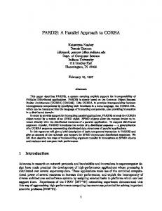
1.2 Motivation: Three Fundamental Bottlenecks A multi-Gbit/s network must be designed to support a wide range of applications, generating different isochronous and nonisochronous traffic with arbitrary bit rates, both narrowband and broadband. The increasing need for high bandwidth networking, under increasingly strict performance constraints, to provide integrated communication services ranging from the ubiquitous 64 kbit/s voice up to hundreds of Mbit/s video and distributed and parallel computing environments has posed fundamental challenges in the design of future networks. To take advantage of the huge bandwidth resource available on optical fiber, three fundamental bottlenecks must be removed when communicating according to the vertically-oriented Open System Interconnection (OSI) model (Fig. 1-1).
Application Presentation Session
Processing Bottlenecks
Transport Network Logical Link Control
Service Bottleneck
Medium Access Control
Datalink Layer
Physical Layer
Electro-Optic Bottleneck
Physical Medium
Figure 1-1. Three Fundamental Bottlenecks
1.2.1 Electro-Optic Bottleneck Although the optical bandwidth resource available on single-mode fiber in the two low-loss windows (1300 nm and 1550 nm) is huge (more than 30 Tbit/s) [Tos90], the electronic components at the network nodes (typically operating at rates up to about 1 Gbit/s), as well as improper architectural solutions, drastically limit the total end-user throughput. Generally, three alternative solutions are used to open up the electro-optic bottleneck:
• single electro-optic interface (i.e., a single pair electro-optic transmitter/receiver) in combination with higher transmission rates; 3
• small number of electro-optic interfaces (coarse WDM); and • large number of electro-optic interfaces (dense WDM). The optical networks can be also classified into monowavelength optical networks and multiwavelength optical networks.
1.2.1.1 Monowavelength Optical Networks In the first network model (Fig. 1-2), the information belonging to different connections are bundled together at one node, debundled and individually switched at the next node, and bundled into other formats for transmission to the next node. Generally, a Time Division Multiplexing (TDM) technique is used for information bundling, which is implemented either in electrical domain, or in optical domain.
Station 1 O E
E w
Station 2 O
w Monowavelength Optical Network
w
O Station n
E/O: electro-optic interface
w
E O
E
Station i
Figure 1-2. Monochannel Optical Network
1.2.1.1.1 TDM in Electrical Domain This solution is used by most actual monowavelength systems such as the Fiber Distributed Data Interface (FDDI) [FDD87], the FDDI Follow-On (FFOL) [LR91], the Distributed Queue Dual Bus (DQDB) [DQD88], the High-Performance Parallel Interface (HIPPI) [Tol92], and the Asynchronous Transfer Mode (ATM) [BS91] in combination with the Synchronous Optical Network
4
(SONET) [Che92]. These systems are of architectures that do not take advantage of the lightwave technology capabilities. They are fundamentally throughput limited because of the technology limits set by classical TDM. The electro-optic and processing bottlenecks at the Physical Layer (PHY), and at the Medium Access Control (MAC) Layer, are greatly exacerbated, resulting in performance hindrance and/or inefficient resource utilization. For example, to sustain a 1 Gbit/s throughput, the station must process packets at the rate of 400 nsec for every 50 byte packet, or 800 nsec for every 100 byte packet, etc. Considering that a fast processor, capable of executing 50 Millions of Instructions Per Second (MIPS), is used, then only up to 20 instructions are allowed to process an ATM cell header of 5 bytes! And this figure gets even worse at higher speeds, where the technological limitations in electronics and processing deteriorate the performance even more [McE92], [Tol92]. The solution therefore seems to be to make use of dedicated hardware, as shown in [Dav93], [MC93], [TS93]. Furthermore, the alternative solution of using large packet/cell sizes is not advantageous either, because it exacerbates the service bottleneck when integrating various types of traffic into the same data stream. Large packet/cell sizes are not advantageous for carrying mixed broadband traffic with different characteristics [BS91], [DJ92]. The question of the precise practical limit of such electro-optic interfaces is therefore still open, but it currently appears very difficult to extend the bit rate beyond 2.4 Gbit/s [Kle92], [Kun92], [McE92], [MC93], [TS93]. Technological breakthroughs are still needed in the electrical domain to open up the service and processing bottlenecks, for the case of single electro-optic interface operating at multi-Gbit/s rates.
1.2.1.1.2 TDM in Optical Domain Another concurrent technique is that of the TDM in optical domain [PSS86], [PBS87], [Hin92]. This is an approach wherein each bit belonging to different packets (generated by different stations/users) is optically compressed in time, and the bits corresponding to concurrently generated packets are time-multiplexed in the optical domain. Two electro-optical interfaces are used at each station (one for the clock signal and the other interface for the data signal). While opening up the bottlenecks in the electrical domain, this solution has the drawback that it shifts the problems into the optical domain. The main difficulties of this solution are connected with the (optical) delay equalization needed to keep the optical pulses aligned in their proper time slots, a formidable task for pulses of tens and hundreds of picoseconds duration [AK89], [JM93]. Furthermore, technologies for multiplexing and switching in the optical path (such as guided-wave and free-space optics) are still in the laboratory phase, and they still need to have their performance improved [Hin92].
5
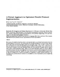
1.2.1.2 Multiwavelength Optical Networks The best architectural models for utilizing the large bandwidth resource available on optical fiber are those based on Wavelength Division Multi-Access (WDMA) [Bra90], [Gre91]. In such architectures (Fig. 1-3), multiple optical channels spaced apart in the spectral domain are used to provide switchable interconnections between any two users. Generally, the stations have one or more electro-optical interface(s), and these networks can be broadly classified as using wavelength agility or not. The question, however, is what kind of WDMA architecture provides the best performance for user and network in the case in which the transmission in one wavelength is essentially limited by the classical TDM technology, and the speed at which data may be switched in the spectral domain is still limited because of, for instance, the non-availability of wavelength-agile components in a rapidly-tunable form (over a wide wavelength range and with high selectivity) [Ram93]. Also, the lack of optical equivalent of electronic buffer memories means that the control functions still need to be performed in the electrical domain (i.e., mixed electro-optical solutions) such as in the case of photonic fast packet switching [JM93].
Station E 2 O
Station O E 1 wΝ
w1
E O w1
E O
wΝ Multiwavelength Optical Network
( w1 - wΝ )
wΝ
Ο Ε Station n
w1
Ο
wΝ
w1
Ο Ε
Ο Ε
Ε
Station i
Figure 1-3. Multichannel Optical Network
1.2.1.2.1 Single-Hop Architecture The first WDMA network model, the so-called single-hop architecture, which is based on the
6
Wavelength-Dedicated-to-User (WDU) concept, makes use of a pure WDM technique for transmission in combination with some form of spectral switching. Wavelength-agile components are used for switching. Examples of such architectures are the Fast Optical Cross-connect (FOX), the Hypass and Bhypass Switches, the Photonic Knockout Switch [Goo89], the Star-Track Switch [LGA90], Rainbow [DGL+90], and others [HKS87], [Meh90], [SGK91], [SBD92]. This architecture presents, however, fundamental difficulties when using distributed control [Ram93]. Typically, a star topology is used, with a central passive node to and from which all communication take place. Each user transmits its information on an unique wavelength, and a pretransmission procedure is needed for the tuning of two end users to the same wavelength. Different alternative procedures are possible (reservation and pre-allocation strategies) [Muk92a], [Ram93], but they all are time-consuming and cause high access delays [HKS87], [LGA90], [SGK91], [SBD92]. This means that this network model is not consistent with bursty traffic needs in terms of low access delay requirements. The wavelength switching is a time-consuming process as well. Neither tunable lasers nor tunable filters are commercially available today that are capable of retuning speeds consistent with the packet/cell switching requirements (i.e., microseconds and less) over a sizable optical spectrum and for a large number of users [TIN86], [KC89], [LZ89], [Bra90], [Ram93]. Nor are they likely to be available in the near future, since such technological breakthroughs are well beyond the current state of the art of lightwave technology [Bra90]. These technological limitations greatly deteriorate the performance for WDU architectures (service bottleneck) and therefore restricts the area of applicability for (fast) packet switching services [AK89], [Gre92]. Also, another bottleneck in WDU networks is because of congestion in the optical power domain given by the optical splitting in the case of passive central node. This limits the maximum number of stations allowed in network, and lasers with high peak optical power are required to increase the number of stations [Bra90], [Bra91].
1.2.1.2.2 Multihop Architecture The second WDMA model, the so-called multihop architecture, is used by several proposed networks such as the Manhattan Street Network (MSN) [Max85], the ShuffleNet [Aca87], [HK91], Store-and-Forward With Integrated Frequency-Time (SWIFT) [CG87], the Lightnet [CGK88], and the Wavelength-Division Optical Network (WON) [Ban90]. A distributed topology is used, with a distributed temporal switching function, in which each station has access to a small number of fixed-wavelength transmitters and receivers (coarse WDM). These wavelengths are assigned to stations in a manner that allows any pair of users to communicate with each other either directly (without hoping), or through one or more intermediate stations (with wavelength hoping). The performance of this architecture is, however, deteriorated in the case of fixed routing and
7
realistic (nonuniform) load pattern [Muk92b]. The load imbalance, due to either traffic intensity variability or traffic pattern variability, has the effect of reducing throughput per station by a factor of 0.3 to 0.5 relative to that of balanced-load situation [EM88]. Alternatively, different adaptive (self-routing) mechanisms can be used in the spectral domain (store-and-forward, hot-potato, etc.) to compensate for variable traffic intensities and/or patterns [AK89], [Ban90], [AS92]. Nevertheless, such architectures are not advantageous for services with strict latency and jitter constraints (real-time traffic). Apart from the drawback of large delay variances [Ban90], [Ros92], these networks suffer also because of the need to reassemble the received data in a correct sequence, a timeand buffer-consuming process. Furthermore, since a packet goes through intermediate nodes (i.e., multiple hops) before reaching the destination node, network (bandwidth) resource is wasted. This poses difficult problems of routing. Sophisticated routing algorithms are required in this case to minimize the (average) number of hops [Muk92b], [Ram93].
1.2.1.2.3 Wavelength-Dedicated-to-Bit Approach Perhaps the most interesting WDMA architecture is the Photonic Interconnection Network proposed for multi-computer communication [SBR92]. This is a multihop architecture based on a dense WDM. A Wavelength-Dedicated-to-Bit (WDB) concept is used, and the communication is done using word-wide parallel transmission through parallel optical channels placed in different wavelengths. By this, communication networks resembling extension of computer busses can be easily developed. The big advantage of such architecture is given by the ease with which the electro-optic and processing bottlenecks can be opened up. However, monolithic multiple-wavelength laser diode arrays with hundreds of lasers and corresponding integrated detector arrays are needed for each station! Actually, such components are extremely difficult to implement, and likely be in the near future [C-HMH+91], [Rog91]. Thus, there is a definite need for better WDMA architectures targeted to effectively share the vast optical bandwidth resource available on optical fiber among distributed users with diverse and conflicting traffic needs, and with peak traffic constraints because of the limited speed of electronics at the electro-optic interface. How should the user-traffic best be partitioned among different wavelengths (i.e., electro-optic interfaces) so that the electro-optic bottleneck is relieved without the need for technological breakthroughs? How does one efficiently control a large number of high speed channels, placed in different wavelengths, to be set up, switched and torn down? Also, how does one increase the concurrence among diverse multiple-user communications into the network architecture? The design of appropriate WDMA architectures, able to open up the electrooptic bottleneck from network nodes without the need of technological breakthroughs (in electrical domain and/or optical domain), thus represents one of the most important issues to be resolved in multi-Gbit/s networks.
8
1.2.2 Service Bottleneck The second bottleneck that prevents the large bandwidth resource available on optical fiber from being used by hosts/users is the so-called service bottleneck between the MAC layer and the higher layers (Fig. 1-1). This bottleneck refers to the difficulties in providing the requested Quality of Service (QoS) for all traffic classes (which compete for common transport resources). In addition to existing communication services (like the ubiquitous voice, file transfer, etc.), future networks must also support broadband interactive services (of type conversational, messaging and retrieval) [CCI88]. The emerging services are of various types for multi-media (voice, video and/or data), multi-rate and multi-point communications [Lid90], [WT90]. Accordingly, the incoming traffic is highly heterogeneous in its characteristics and performance requirements, with different and contradictory (bandwidth) resource demands, holding times and call/session arrival rates. Moreover, each type of traffic differs in its admissible access and transit latencies, jitter (delay dispersion), end-to-end loss sensitivities, reliability, need for sequenced delivery, etc. Additional synchronization requirements, such as inter-media synchronization facilities across two or more real-time channels in a multimedia communication/retrieval [LG90a], [RVR92], further complicate this picture. So the understanding of application requirements is a prerequisite for the proper design of future high-performance networks. Generally, the incoming traffic can be divided into two main classes, isochronous (real-time) and nonisochronous (non real-time), each with distinct performance requirements [GRV90], [RB90], [BS91], [RD91b]. Isochronous traffic generally includes Continuous Bit Rate (CBR) traffic and Variable Bit Rate (VBR) of continuous type, e.g., VBR video traffic. In contrast, nonisochronous traffic sources generate intermittent traffic and usually alternate between active and inactive periods. The lengths of these two periods may vary randomly, and, during active periods, bit rates may be constant or may vary randomly depending on the application.
1.2.2.1 Isochronous Traffic As the term indicates, information is generated, for this class, either in a steady time-synchronous mode in the case of synchronous traffic, or in a nearly synchronous mode in the case of isochronous traffic. This traffic, characterized by long holding times and modest setup times, may accept large access delay, but puts rather stringent requirements on the network in terms of transit delay (up to tens of milliseconds), delay variance (i.e., jitter), and bandwidth demands (for video applications). It also has flexible loss sensitivity. Furthermore, the isochronous sources are generally uncontrollable (i.e., they cannot stop or slow down/vary their traffic rate during a call). In supporting synchronous or isochronous services, the network must be able to provide real or virtual connections with guaranteed performance (quality) of service as negotiated at the call setup. The negotiated performance can be of various types, such as an upper bound on call block-
9
ing probability, a lower bound on throughput, an upper bound on transit delay and/or jitter, an upper bound on loss rate, or a combination of these. Apart from the heterogeneity in bandwidth demands, the main network task requested by an isochronous (bandwidth-sensitive) service is isochronicity in the transport of data (i.e., bounded delay and jitter for isochronous real/virtual connections). This requires that both bandwidth and processing resources are guaranteed during the call, and therefore poses the main challenge to the proper design of transport-oriented entities, such as the resource management (congestion control) and routing in the network.
1.2.2.2 Nonisochronous Traffic On the other hand, nonisochronous sources generate bursty information of random lengths at random times and, usually, with a low activity factor, i.e., the source is active only a fraction of the time. These sources are much more controllable than the isochronous sources, i.e., they can stop or slow down transmitting if requested from the network. Most of the computer data applications fall into this class. The variety of computer application models [Lid90] translates into a variety of performance needs expected from the underlying transport network. Furthermore, the MAC mechanisms for such traffic are based on different delay-throughput trade-offs. Also, the transport mechanisms must provide delivering of data in recognizable form (without errors). While actual computing paradigms like terminal-timesharing, transaction-oriented and mainframe-to-mainframe (best-effort applications) are readily supported by a Connection-Oriented (CO) or Connectionless (CL) transport model, mainly because of the reasonable services needed (low throughput and low latency to large throughput and moderate latency requirements), the picture is completely changed in the case of the emerging distributed/parallel processing environments. Thus, for the client-server paradigm, the communication requirements are quite different and much more demanding, since both the very low response time and large throughput are crucial. Here, remote software operations such as Remote Procedure Call (RPC), Inter-Object Communication (IOC) and Demand Paging (DP) invoke edge-to-edge network delays of tens and hundreds of microseconds, and data bursts with lengths in the range up to hundreds of kbits [Lid90]. Very stringent requirements! For instance, a data message of 100 kbits with a transmission speed of 10 Gbit/s corresponds to a data transmission time of 10 µsec, i.e., 20 µsec for both sides of a link (transmission and reception). Also, the propagation time on optical fiber (5 µsec/km) is comparable with these figures. The first conclusion is that such figures can be provided only by a CL transport mechanism. The second one is that the underlying transport network must work in extreme conditions, such as at the highest possible transmission speed, and must have the choice of optimization for the physi-
10
cal/logical topology so as to reduce the propagation delay to the minimum possible. The protocols (medium access and transport) should also be simple and flexible, with adjustable parameters for minimum processing delay. Admission control mechanisms acting at a burst level (fast reservation schemes) should be used. The error recovery schemes should work on an edge-to-edge or network basis [BSW91]. The flow control protocols should work on a preventive basis and be entirely dedicated to applications [MElZ90].
1.2.2.3 Transport Mechanisms Ideally, "uniform control mechanisms" should be applied to the transport across the optical media. This is, however, extremely difficult because such an approach poses tremendous technical difficulties on the dimensioning of network elements and the allocation of resources to competing user applications. The resulting equipment (hardware and real-time software) turns out to be very complex, and the processing bottleneck is greatly exacerbated. Different sorts of problems may occur, for instance, when carrying mixed broadband traffic, with growing inhomogeneity, over ATM networks with rate-based statistical multiplexing. These are mainly connected with the complexity of statistical multiplexing (policing first-moment and/or second-moment statistics on a real-time basis in a gigabit network is extremely computationintensive), network congestion under peak traffic loads, interference among user-traffic classes, ATM cell size and the pushing of different functions, such as flow control and error recovery, to the edge of the network (with the result of conflicting the fundamental principle for supporting statistical multiplexing and CBR, which requires that elaborate congestion- and rate-control schemes be executed on a real-time basis inside the network, and not at the edge) [BS91], [HS91], [VS91], [DJ92], [Lea92]. One of the most important research issues in ATM is related to the characterization of the arrival process for bursty traffic, which is still an open issue. Actually, there is no agreed definition for the burstiness of such a traffic and, accordingly, different traffic descriptors may be used that are based on diverse parameters (peak bit rate, average bit rate, bit rate variance, squared coefficient of the interarrival times, etc.) [KS90], [BS91]. Examples of models used in the characterization of diverse arrival processes are MMPP, renewal process, n-superposed IPP, etc. [KS90]. Furthermore, an uncontrolled access for additional traffic of all kinds may overload the network (bandwidth and processing) resources to the extent of performance degradation for already supported traffic. Large bursts of delay-insensitive traffic may worsen the delay performance for time-critical traffic. Further research is needed in characterizing the superposition process (single queue with multiple arrivals) in ATM networks [Hui90]. One can, for example, model each bursty source separately, but this may lead to an intractable model for an increased number of connec-
11
tions multiplexed on the same link. Alternatively, one can superpose all connections into a single or a few number of sources, but this raises the problem of the need for a proper, and precise, modeling of the superposition process. Examples of approximations that may be used to obtain the parameters of the superposed process are the matrix geometric approach (and its modification), the fluid flow approximation, the discrete time model, etc. [KS90]. The ATM cell size (53 bytes) has also been a matter of considerable debate because of the need to compromise between the conflicting demands of (voice) packetization delay (echo problems) and transmission (bandwidth) efficiency. ATM has the potential to handle a wide range of CBR and VBR services in an uniform way. However, it is less advantageous for time-critical (computer) communications, such as in distributed computing applications. This is due mainly to the extra processing needed for segmentation/reassembly of data packets into/from ATM cells, with the penalty of extra latency in data transport [MC93], [ST93], [TS93]. The technique of (self-routing) fast packet switching used in ATM is not consistent with most actual WDMA architectures. The needed wavelength-agility, for instance, is currently beyond the state of the art [Bra90]. Additionally, the switch throughput is fundamentally limited in the ATM case by the limited capacity available in the control channel (within the switch) and not by technological limitations on optical networks such as power-budget or dispersion [Hen89], [Bra91]. Technological breakthroughs are needed in switch implementation to alleviate this bottleneck. Thus, there is a definite need for novel ways of dealing with the conflict between the heterogeneity and the performance (needs) of application traffic. How does one control the access to a multi-Gbit/s network by a number of different traffic classes, so as to provide appropriate service requirements for each? Which is the best solution for traffic integration? How does one resolve the conflict between the set of (user) traffic constraints and the set of (technological) network constraints? Proper schemes are required for multiplexing, transmission, switching and (connected with this) for multiaccess mechanisms to provide the best performance for users and network. Efficient solutions need to be designated for contention resolution among diverse classes of traffic for common (bandwidth, buffers and MAC processing) resources, so as to minimize the possibility of overwhelming resource. Efficient solutions for contention resolution among users/hosts within the same class of traffic are needed as well.
1.2.3 Processing Bottleneck One of the most severe performance bottlenecks to be considered in computer communications is connected with the slow-(software)-processing-fast-transmission bottleneck. If the end system functions for isochronous services mainly involve coding/decoding techniques and end-toend synchronization, the picture is much more complicated for computer type applications. The
12
processing involved here by the end-to-end protocols (and associated code) in different OSI layers is not keeping pace with the actual multi-Gbit/s rates on optical fibers [DDK+90], [MElZ90], [DJ92]. To sustain 1 Gbit/s throughput, for instance, the station must process packets at a rate of 10,000 packets per second for (long) packets of 100 kbits length, and this figure approaches the actual limit for transport protocol processing rates [NRS90]. This processing bottleneck has two components in terms of the increased ratios of (software) processing time to cell/packet transmission time and of propagation delay to cell/packet transmission time. The first component means that there is not enough processing power available to handle the immense amounts of data on optical fiber, whereas large bandwidth-delay products mean that critical problems of management (connection establishment, resource allocation, etc.), flow control and error handling are introduced. The overall effects are significant bandwidth waste and a degrading of network throughput and latency [DDK+90], [DJ92]. Moreover, the increased ratio of processing time to cell/packet transmission time makes it extremely difficult to implement node-by-node control schemes. How does, for instance, one control (in a distributed manner) the flow over a multi-Gbit/s network in which the ratio of propagation delay to cell/packet transmission time is very large, i.e., with thousands of cells/packets enroute between a particular source-destination pair? How does one detect, identify and correct different kinds of errors and/or faults in a "real-time" manner specific to different traffic classes? Simpler and better control mechanisms for connection management, flow control and error handling are required in high-speed networks to open up this bottleneck. They must be capable of managing large data flows in transit over the network, so that the throughput is restricted only by the source capacity or the sink ability of the end hosts. The user data must be delivered to the higher layers (on top of the transport layer) in-sequenced, free of errors and of duplicates. Furthermore, the network latency and responsiveness should be minimized for delay-sensitive applications of the kind used in parallel, distributed system environments. That means simpler and low-latency multiaccess control mechanisms are required as well. Generally, the protocol functions of the lower four layers in a traditional seven-layered OSI model are dictated by parameters of the network model and technology. On the other hand, the protocols in the upper three layers are designated to serve the needs of (different) applications. To open up the processing bottleneck, fewer and simpler protocol layers are required, as well as elimination of redundant instances of different (protocol) functions, such as multiple packetizing/ depacketizing, resequencing, error recovery and encryption/decryption. The new protocols should be designated with the emphasis on streamlining the normal data transport processing (so-called success-oriented design). The stream-lined, normal operation of the protocol stack should be implemented in hardware (very near the physical port), and the abnormal conditions (such as errors) should be made programmable and implemented in software (so-called lightweight protocols). Key issues related to the efficient implementation of protocols, such as shortening the length of the instruction path, minimum possible memory moves (so-called single-copy architectures), low-over-
13
head process structures (i.e., modification of the protocol syntax), minimum number of calls to the operating system, etc., must be addressed as well [DDK+90], [LaPS91], [MS92], [BP93], [DAP+93], [DWB+93]. Furthermore, to compensate for the increased ratio of propagation delay to cell/packet transmission time, some form of structural and/or functional parallelism (or pipelining) must be used in processing the different protocols and/or data structures involved in a communication process [Zit91], [GNI92], [Kle92], [ITN93].
1.3 Solution Approach The fundamental shift in technologies and their trade-off forces us to consider new alternative approaches to the integrated multi-Gbit/s communication over multiwavelength optical networks. Removing the fundamental bottlenecks, as described previously, and fully realizing the performance benefits of using optical fibers, imposes the search for new (architectural) communication models. There are several ways to conduct the study of the above problems. Our approach is a theoretical one, and we make use of an integrated broadband Local Area Network (LAN) environment to address these fundamental issues. This provides us with the advantage that it does not require sophisticated routing algorithms (compared to Wide Area Networks or Metropolitan Area Networks), and therefore we can focus on the above bottleneck issues. Routing in a LAN environment is trivial as there is no choice of direction in nodes. Furthermore, our purpose is to push the limits of optics and data rates of up to 10 Gbit/s are considered for transmission. Performance and cost-effective LAN architectures, able to handle both stream traffic and bursty traffic in an effective way, at a range of data rates spanning several orders of magnitude, need to employ efficient methods to share the system resources among the network stations. This must be done in a manner that circumvents the mismatch between the transmission and processing speeds and, at the same time, provides adequate quality of service to all user applications. Generally, existing integrated LANs employ sophisticated mechanisms to control and coordinate access to the communication media, so that the service performance requirements of each user application are met. But because of this complexity, processing limits performance and the network (transmission) resources are not efficiently utilized. This is the kind of approach in which the performance needs of the user applications are adapted to a given network environment. This means that the network architecture is designed first and then complex functions are incorporated in different protocols (MAC and transport) to satisfy the performance needs of the applications. The approach advanced in this thesis is just the reverse, i.e., a top-down approach. According to this, we design and develop the underlying transport entities based on the needs of the specific applications (e.g., response times and throughput). Examples of network entities involved in a communication process are (virtual) configuration/topology, resource management, diverse
14
control/protocol mechanisms, transmission and switching schemes, etc. This approach corresponds to the hierarchical top-down system design process seen from the performance viewpoint, as treated in [Lyn72]. The new model of parallel communication put forth in this dissertation does not follow the standard layering approach of other LANs. Instead, a horizontally-oriented model is advanced for the communication process to open up all three fundamental bottlenecks. For the reasons cited in section 1.2, a direct extension of the standard, vertically-oriented OSI model to a multigigabit optical network environment may not be suitable. Furthermore, the design follows new concepts in opening up the electro-optic and service bottlenecks. A new WDM architecture is used, that is based on the Wavelength-Dedicated-to-Application (WDA) concept. The network has an architecture structured to a multiclass network model with a pipelined model used for communication. A coarse WDM is used to open up the electro-optic bottleneck. Specific time-synchronous channels, placed in different wavelengths, are dedicated to different applications and control mechanisms according to their traffic characteristics, e.g., CBR and/or VBR isochronous traffic, computer data transfer (with focus on latency), application-specific control mechanisms for media access, error handling and flow control. We use separation of different user-traffic, and of information traffic from control traffic, in order to open up the service bottleneck. Furthermore, separate, simplified and application-oriented protocols supporting both packet- and circuit-switching are used to open up the processing bottleneck. The performance results will clearly indicate the feasibility of this new concept, as a candidate for the future multi-gigabit communication over multiwavelength optical networks. Such an architectural model offers the choice of performance restricted by optics, and less by electronics or processing. It offers the choice of reducing the latency in communication to limits that are commensurable with those given by the finite speed-of-light in fiber. Real-time services, with specified delay and bandwidth requirements, can be easily provided. Simple and low-processing applicationoriented protocols are used, with no interference among user-traffic classes. It is therefore very suitable for service integration, irrespective of traffic and network conditions. There is no need for technological breakthroughs, no need for wavelength agility, and LAN environments can be easily developed that are capable of supporting large number of supercomputers. The disadvantage of this approach is given mainly by the hardware replication that is needed in every node for each traffic class.
1.4 Related Work Considerable research and development effort has been done to understand and to solve the technical challenges associated with gigabit networking. Although (asynchronous) gigabit transmission systems have been deployed, this has not meant that the networking bottleneck problem
15
is solved. Generally, the research and the development of very high speed LANs does not appear to be well understood. Besides increasing the raw speed, other issues like appropriate architectures, switching and transport schemes, network protocols, resource management, host computer architectures and operating systems, etc., must be addressed as well (Fig. 1-4). Without appropriate solutions for all these issues, the benefits of multi-Gbit/s LANs can not be fully realized by endusers. Thus, research and developing of gigabit LANs is a challenge.
• Reduction/compensation of the communication latency • parallel protocol processing • parallel communication • parallel processing and communication • coordination of network dynamics with those of application (applic. level framing) • sending sets of data in anticipation • Multimedia traffic integration • requirements of coexistence, integration and interaction of different media (traffic) • three possible levels of integration • human interface level • service level • media level • multiaccess mechanisms • Multimedia synchronization • sync of iso & noniso communications on temporal and spatial basis • temporal composition/integration of related real-time data streams (cont. sync) • two components • stream synchronization • object synchronization • Fast routing, switching and signaling • circuit-switching packet-switching cell-switching • time domain frequency/wavelength domain • channel timing formats • support for services • point-to-point (one sender and one receiver) 16
• multicast (one sender and multiple receivers) • conferencing (multiple senders and multiple receivers) • Mechanisms for resource management and flow control • traffic shaping • channel sharing • resource creation demand reduction (admission control) • reactive preventive nature • diverse temporal scales (network-, call-, burst-, packet- and/or cell-level) • dynamic windows rate control • Network reliability • self-healing • fault-tolerant systems • forward error correction • redundant (dispersity) transmission/routing
Figure 1-4. Main Research Issues in Gigabit Networking
As a general observation, most of actual multi-Gbit/s LAN experiments are aimed at alleviating one or two of the above-mentioned bottlenecks, but this is done at the expense of exacerbating the other(s) bottleneck(s). Technological breakthroughs are therefore needed in optical and/or electrical domain(s) in order to get performance limited by optics, and not by electronics and/or processing, as shown by several notable recent experiments. Perhaps the best example is given by the ATM experiments, where the electro-optic and service bottlenecks are opened up, but at the expense of exacerbating the processing bottleneck. To manipulate large amounts of multimedia data in a multi-Gbit/s ATM environment (i.e., beyond the actual standard data rates of 155 and 622 Mbit/s), new and sophisticated switching fabrics embedding advanced technologies within them (such as photonics, BiCMOS and GaAs MESFET) are required [Cha91], [JC91], [RW91], [Hin92]. Gidron and his colleagues have recently proposed and studied the TERANET architecture [Gid91]. This is a multichannel optical network where all seven layers of the OSI standard are studied in a multigigabit environment. In order to provide both circuit- and packet-switching services, a hybrid multiple access scheme is used which combines WDM and subcarrier Frequency Division Multiplexing (FDM). This is an advantageous method, since it reduces the bandwidth
17
requirements on the optical filters. A passive star topology is used. Each wavelength can support four to six subcarrier channels, and Phase Shift Keying (PSK) modulation formats are used for them. A packet-switching network is implemented through a multihop architecture and using ATM. End-user capacities of 1 Gbit/s are provided for both types of services. The most interesting idea advanced by this experiment is the differentiation of bandwidth and MAC resources between the isochronous and nonisochronous traffic, which is advantageous for alleviating service and processing bottlenecks. However, wavelength-agile components are still used. Also, the solution advanced for the packet-switching services (ATM transport form in combination with multihop architecture) is not advantageous for delay- and jitter-critical (computer) communications. The RAINBOW network [DGL+90], [Gre92] provides, perhaps, the best example of service bottleneck in multigigabit environments. An WDMA architecture of type WDU is used with fixed frequency optical transmitters and tunable optical receivers. A passive star topology is used. Retuning times (i.e., access delays) of units and tens of milliseconds have been obtained, which are not satisfactory for packet-switching services. Also, another factor limiting the performance is connected with multicast service requirements. This drawback, which is specific for such architectures, refers to the difficulties in solving the (possible) contention when multiple packets, from a number of transmitters, must be simultaneously transmitted to the same receiver [Bra90]. One of the most interesting experiments, the STARNET architecture, is reported in [PG91]. This is a hybrid multichannel optical network implemented on a passive star topology. It provides support for both high-speed (100 Mbit/s) packet-switching applications and multi-Gbit/s (3 Gbit/s) circuit-switching interconnections. A coherent WDM technology is used for the detection of optical signals (dense WDM). Two separated logical networks are provided, a multi-Gbit/s circuit-switching network with star topology, simultaneously with a high-speed packet-switching network with virtual ring topology. Again the principle of traffic differentiation is advanced and application-oriented logical networks are designated. By this, the properties of optical fibers are better employed to open up all three bottlenecks. The solution proposed for packet-switching services is, however, not the best for multigigabit applications. Similar to token-ring FDDI, store-and-forward ring topologies do not perform well at multi-Gbit/s mainly because of the low amount of concurrence in accessing the transport media, with the consequence of poor performance for access delay and low efficiency in (bandwidth) resource utilization [RB90].
1.5 Thesis Outline The goal of this thesis is to conduct an in-depth study of an alternative solution that is proposed to open up all three bottlenecks. To do that, a specific architectural model will be first developed, for the communication process, which is suitable for integrated multigigabit communications. Critical evaluation of the basic concepts behind this model will be done, and a case-study network architecture is chosen to address the typical research topics, i.e., multiple data stream
18
synchronization and multiaccess and switching mechanisms for isochronous and nonisochronous traffic. Furthermore, detailed theoretical studies of modeling and performance analysis will be conducted in order to obtain the performance measures of the proposed architecture. Finally, comparative evaluation of the performance aspects for different alternative solutions, possible for diverse network entities, will be done with the purpose to investigate the limits and the advantages of this approach. In Chapter 2, a horizontally-oriented model is advanced for the communication process to alleviate the fundamental bottlenecks in an integrated multi-Gbit/s communication over multiwavelength optical networks. The basic principles and solutions adopted for this model (i.e., the separation principle, the wavelength-dedicated-to-application principle, the synchronization principle and the principle of performance optimization) are described and motivated. A new WDM architecture is used that is based on the Wavelength-Dedicated-to-Application (WDA) concept. The network has an architecture structured to a multiclass network model with a pipelined model used for communication. A coarse WDM is used to open up the electro-optic bottleneck. Specific timesynchronous channels, placed in different wavelengths, are dedicated to different applications and control mechanisms according to their traffic characteristics, e.g., CBR and/or VBR isochronous traffic, computer data transfer (with focus on latency), application-specific control mechanisms for media access, error handling and flow control. We use separation of different user-traffic, and of information traffic from control traffic, in order to open up the service bottleneck. Furthermore, separate, simplified and application-oriented protocols supporting both packet- and circuit-switching are used to open up the processing bottleneck. A case-study network architecture for a new class of multiwavelength optical networks is presented and described in Chapter 3. This is designated according to the horizontally-oriented communication model, with Wavelength-Dedicated-to-Application (WDA), advanced in Chapter 2. Different design choices in constructing such architectures are presented and discussed. Furthermore, discussion of some basic issues and solutions chosen in the design and implementation of such kind of architecture, as well as requested performances, is provided. Communication services are defined. Accordingly, definition of classes and subclasses of traffic is provided as well. Chapter 4 is devoted to the problem of (low-level) multiple data stream synchronization in a WDMA network based on the WDA concept. It includes the issues of network designing and dimensioning for a proper point-to-point transmission, bit synchronization (jitter compensation) and slot synchronization. Proper algorithms for frame synchronization are needed as well. Detailed theoretical analysis and performance evaluation are provided for the study of typical cases, which include one, or multiple, data channel(s) and one, or multiple, control channel(s), all placed in different wavelengths on the same fiber. Discussion of some basic implementation issues is provided as well. In chapter 5, we discuss the problems encountered in developing application-dependent MAC and switching mechanisms in a WDMA network based on the WDA concept. A family of pro19
tocols for a ring LAN environment is described, and their performance evaluated by theoretical analysis. Detailed theoretical studies are provided in this chapter to study the performance of application-dependent MAC protocols and their behavior with varying system characteristics. In particular, the performance of a class of centralized MAC protocols for isochronous traffic and a class of distributed MAC protocols for nonisochronous traffic are evaluated in terms of their main parameters of interest like, for instance, call setup delay and blocking probability for isochronous traffic, and access and end-to-end delay for nonisochronous traffic. The impact of variable system and user parameters on performance is also examined. Discussion of some basic implementation issues is provided and future research issues of interest are briefly mentioned. Furthermore, in order to provide bounded delay and jitter requirements for loss-free nonisochronous traffic, a new approach is suggested in chapter 5 for congestion control and bandwidth allocation, which is of type Rate Controlled Admission with Priority Scheduling Service. We call this Dynamic Time Sharing (DTS). This approach is based on guaranteeing specific traffic parameters (bandwidth requirements) through a policer/shaper unit, and then optimizing the bandwidth assignment, within the network, for specific parameters of interest (such as delay or jitter, and loss). The optimization process is based on the parameters guaranteed by the shaper. A batch admission policy is used at the edges of the network according to a specific framing strategy to follow the traffic (peak bandwidth) characteristics of different traffic subclasses. On the other hand, another framing (congestion control) strategy is used within the network, which is based on different (delay/loss) requirements of the traffic classes. Proper management of bandwidth and buffer resources is provided in every (switch) node of the network, such as to guarantee the diverse performance of interest, regardless of traffic statistics, network size and transmission speed. Chapter 6 summarizes the results and the contributions of this thesis and gives concluding remarks and suggestions for further work. In particular, continued efforts are recommended in developing better resource allocation mechanisms to adaptively respond to different network and traffic (fluctuation) conditions, in developing the specific transport protocols (flow control and error handling) involved in a WDA network, as well as in developing of better WDA architectural models, with more subnetworks, each of them completely dedicated to a specific type of service (CBR, VBR, graphics, client-server, etc.), with optimized topologies and simple, low-delay, applicationoriented media access and transport protocols.
1.6 Contributions of the Thesis In this thesis, the problem of alleviating the three fundamental bottlenecks in a multigigabit environment based on multiwavelength optical fibers is posed. An original solution to this problem is advanced. The major contributions of this thesis are:
• identifying key bottlenecks in a multigigabit integrated communication over multiwave-
20
length optical network;
• investigating possible models for the communication process in a multigigabit optical environment;
• introducing a new, horizontally-oriented, model for the communication process over multiwavelength optical networks;
• introducing a set of basic concepts for the horizontally-oriented communication model (i.e., the separation principle, the wavelength-dedicated-to-application WDA principle, the synchronization principle and the principle of performance optimization, with five components) and critical evaluation of these concepts;
• identifying directions and research topics for optical networks based on the WDA concept; • design of an architectural solution advanced to solve the problems encountered in alleviating the fundamental bottlenecks;
• solution advanced to the problem of temporal synchronization among multiple data streams placed in different wavelengths on the same fiber;
• a set of specific multiaccess mechanisms, for isochronous and nonisochronous traffic, to be used in WDA networks;
• a new approach for congestion control and resource allocation for bursty traffic, to provide delay and jitter guarantees;
• analysis and evaluation of specific performance measures for diverse network entities and protocols;
• identifying factors limiting the performance, and of solutions for performance improvements; The work presented in this thesis was partly published in [PS90], [PS91], [PIR+93] and [PS93].
1.7 Summary This chapter defined the scope and motivation of this research. Existing solutions and current approaches were discussed. The thesis is briefly outlined, and the major contributions are mentioned.
21
Chapter 2
Integrated Network Model
Contents 2.1
A New Communication Model
.
.
.
.
.
.
.
.
.
.
.
.
.
.
.
.
23
2.1.1 General Requirements .
.
.
.
.
.
.
.
.
.
.
.
.
.
.
.
.
24
.
.
.
.
.
.
.
.
.
.
.
25
2.1.2 Pipelining the Communication Process 2.1.3 Multimedia Traffic Integration
.
2.1.4 A Parallel Communication Model 2.2
Basic Concepts
.
.
.
.
.
.
.
.
.
.
.
.
.
.
.
.
.
31
.
.
.
.
.
.
.
.
.
.
.
.
.
32
.
.
.
.
.
.
.
.
.
.
.
.
.
.
.
.
.
34
2.2.1 The Separation Principle
.
.
.
.
.
.
.
.
.
.
.
.
.
.
.
.
35
2.2.1.1
Separation of Application Traffic .
.
.
.
.
.
.
.
.
.
.
35
2.2.1.2
Separation of Data Traffic from Control Traffic .
.
.
.
.
.
37
2.2.2 The Wavelength-Dedicated-to-Application Principle 2.2.3 The Synchronization Principle
2.3
.
.
.
.
.
.
.
.
.
.
38
.
.
.
.
.
.
.
.
.
.
.
41
2.2.4 The Principle of Performance Optimization
.
.
.
.
.
.
.
.
.
.
43
.
.
.
.
.
.
.
.
.
.
44
.
.
.
2.2.4.1
Application-Oriented Topologies
2.2.4.2
Resource Management
.
.
.
.
.
.
.
45
2.2.4.3
Application-Oriented Transport and Switching
.
.
.
.
.
.
47
2.2.4.4
Application-Oriented Multiaccess Mechanisms
.
.
.
.
.
.
50
2.2.4.5
Transport Protocols
Summary
.
.
.
.
.
.
.
.
.
.
.
.
.
.
.
.
.
.
.
.
.
.
.
.
.
.
52
.
.
.
.
.
.
.
.
.
.
.
.
.
.
55
Abstract This chapter advances a new approach for integrated multi-gigabit communication over multiwavelength optical networks. The network bandwidth resource is shared among users according to the Wavelength-Dedicated-to-Application (WDA) concept. Time-synchronous channels placed in differ-
22
ent wavelengths are dedicated to different applications and control mechanisms according to their traffic characteristics, e.g., CBR and/or VBR traffic, computer data transfer, application-specific control mechanisms for media access, for error handling and flow control. A parallel, horizontallyoriented communication model is used to open up the three fundamental bottlenecks in an integrated multi-gigabit network. The basic principles and solutions of this model are presented and motivated.
2.1 A New Communication Model The design (and performance evaluation) of an integrated multi-gigabit network is an important and difficult problem. It generally represents an example of the class of generic resource allocation problems, since the main components of this problem are connected with resolving conflicts. Namely, given a set of user (traffic) constraints and another set of (technological) network constraints, how does one resolve the conflict between these two sets that arises when more users require access to the same resource at the same moment? Usually, it is extremely difficult, if not impossible, to exactly predict when to expect a request for access to the resource and for how long the user will hold this resource. Further complication is due to the fact that some users may expect immediate access to that resource and/or may require it only for occasional use. Also, extra requirements in terms of large throughput needs and isochronous data transport heavily complicates the design of an integrated multi-gigabit network. Because of that, the fundamental assumption that the main network resources (i.e., communication and switching resources/bandwidth, buffer space and processing capabilities) are both observable and controllable, no longer suffices [Kle90], [Kle92]. The major problem faced in an integrated multi-gigabit network environment is connected with the lack of "actual" global knowledge regarding the system state. The distance between interacting users may become a very major problem with regard to the interaction speed and the bandwidth of the communication link. Even if the state information received in different stations is complete and correct, it may be that this information is of no use with regard to the time constraints of different applications. This non-determinism, which is specific for distributed systems, is greatly exacerbated in a multi-gigabit environment with large bandwidth-delay products. The (relatively) long point-to-point communication delay is a fundamental limitation due to the finite speed-of-light in fiber (about 2 ∗ 108 meters per second). We have moved now into a new domain where the design considerations are completely reversed. Specifically, we have passed from a capacity-limited design (non-gigabit networking) to a latency-limited design (gigabit networking), as shown in Fig. 2-1 [Haa92], [Kle92].
23
ss1k
ss21
ss11
ss2k S1
wm
S2
w1
Multiwavelength Optical Network
w1 wm
Si: station i ssik: substation k connected to station i
wm w1
(w1 - wm) Sn
w1
wm
Si
ssnk
ssi1 ssn1
ssik
Narrowband Environment
Broadband Environment
• Throughput limited by network
• Throughput limited by application/host
• Queueing delay dominant
• Propagation delay limitation
• Protocols designed for lossy and slow
• Success-oriented design • Lightwave protocols
networks
• Capacity-limited design
• Latency-limited design
Fig. 2-1. Need to Rethink the Network Architecture
2.1.1 General Requirements To efficiently cope with these problems, the inherent bottleneck due to the layering process in a vertically-oriented OSI communication model must be opened up. Namely, all three abovementioned bottlenecks must be opened up. Furthermore, the latency in communication should be also reduced. Actually, we consider that reducing and/or compensating for the latency is perhaps the most important research issue to be done in gigabit networking. 24
But because only making use of gigabit transport channels and faster processors does not actually help too much in reducing the mean and/or maximum response time of a gigabit network (with respect to multi-megabit networks) [Kle92], new and better communication models need to be conceived. The latency in data transport and processing should be hidden, as much as possible, by using maximum possible pipelining and parallelism in the communication process. Some forms of parallel processing and parallel transmission must be used. The processing pipeline must be continuously filled (including the application process), and protocols should be implemented such as the host operating system is not involved. This also affects the solution of choice for diverse contention resolution mechanisms in a multigigabit network environment, as the reactive (adaptive feedback) control algorithms are no longer suitable. Congestion-tolerant, loosely coupled control algorithms embedded in the network stations are required. Furthermore, given the large bandwidth-delay products existent in a multigigabit optical network (effect of the finite speed-of-light latency), some forms of managing the indeterminism of state in stations must be also envisaged [TF93].
2.1.2 Pipelining the Communication Process There are four general methods of resolving conflicts in a (centralized or distributed) system, i.e., queueing, splitting, blocking and smashing [Kle90]. They have different consequences and are applicable to communication services as well. One of the most common method for conflict resolution, queueing, resolves the conflict by allowing only one user at a time to access the resource while the other users wait for their turn. This is not advantageous for multigigabit environments, with focus on latency. On the contrary, the splitting policy splits up the resource into smaller resources, each of them simultaneously dedicated to the competing users. This is a better solution for opening up the above-mentioned bottlenecks, since the bandwidth now represents one of the most plentiful resource available, and the buffering and processing resources are cheap. It is also most adequate for introducing parallelism into protocol processing and data transmission. The third policy (blocking) provides service only to one user whereas the other competing users are blocked. Finally, the smashing method is based on blocking all the users when more users request service. The last two solutions are not suitable for computer data applications. There are several ways to introduce parallelism into protocol processing and data transport. Our objective is to find out the best alternative solution for performance increase in the case in which multiple data streams, transported on multiple wavelengths, are operated upon by multiple instruction sets, running on multiple processors. Three levels of parallelism are generally identified for a communication process, which are given by the degree of granularity (i.e., coarse grain, medium grain and fine grain) used when introducing parallelism into protocol processing [JSB90], [Haa91], [Zit91], [GNI92].
25
Typically, coarse grain processing involves high-level functions or tasks assigned to individual processors such as, for instance, in the case of connection-dedicated-to-processor approach. Despite its simplicity (which is advantageous for opening up the processing bottleneck), this solution has the drawback that the degree of parallelism is limited by the number of active transport connections, and therefore limited gains in throughput and latency are obtained. Furthermore, this solution does not actually make use of parallelism within the communication process (but rather inside the network). Another example of coarse grain processing is given by the layer-dedicated-to-processor solution. One (or more) processor(s) are dedicated here to a single layer and the protocol stack is composed of a pipeline of processors. This also has the advantage of simplicity, but the communication process is still based on the vertically-oriented OSI model, with the above-mentioned drawbacks. A layer-pipeline model is used here for communication in the sense that the layers (protocol layers and physical medium) are implemented "on top of" each other. Each packet moves step-by-step through this layer-pipeline, so that the communication latency Tcomm is determined by the sum of all delays of the component layers/stages (Fig. 2-2).
Physical Application
Presentation
Medium
Presentation
Layer 7 (transm.)
Layer 6 (transm.)
Layer 0 (medium)
Layer 6
Layer 7
(receive)
(receive)
Stage1
Stage2
Stage8
Stage14
Stage15
Layer 7 : Application Layer 6 : Presentation Layer 5 : Session Layer 4 : Transport Layer 3 : Network Layer 2 : Datalink/MAC Layer 1 : Physical Layer Layer 0 : Physical Medium
Application
14
T comm =
∑
i=2
T Stage
i
Figure 2-2. Layer-Pipeline Model
Such a layer-pipeline model supports only parallelism of structural nature, i.e., several packets may reside, and be processed, concurrently in different layers of the communication pipeline. This is not a parallelism of functional nature, i.e., within the communication process. The pipeline is triggered by the slowest stage and for optimal (throughput) performance, all stages in the pipeline must have approximative the same delays. On the other hand, optimal performance for latency are obtained when the delay of all pipeline stages are minimized. This hardly complicates
26
the issue of reducing the processing bottleneck. Given the large bandwidth-delay products available in a multigigabit optical network, such a pipeline model is effective only when the application layer generates large messages (or files) that are larger than the bandwidth-delay product of Layer 0, to prevent latency-bounded communication [Kle92], [TF93]. For instance, in [Kle92] it is shown that, to accommodate propagation delays (TStage0) of 15 milliseconds, gigabit channels begin to pay off only for large message sizes of 10 Megabits or more. This communication model may, therefore, become performance-limited. It is restrictive for applications in which the focus is on latency. Furthermore, this solution has other drawbacks, such as the need for (context) switching, communication and synchronization (overhead) at layer boundaries. Finally, we mention our belief that the advent of an increased range of applications, with different and conflicting performance requirements, will likely increasingly reveal the inadequacies of the layered communication architecture as a model for real-time (distributed) systems. A better solution for parallelism is provided in the case of medium grain processing, whereby the size of tasks assigned to each processor is reduced. The parallelization is done in this case at the level of a single data unit (e.g., packet-dedicated-to-processor approach). For instance, a multiprocessor pool is dedicated to the (transport) protocol and each incoming packet is assigned to the next available processor to carry it through the (transport) protocol stack (Fig. 2-3). This is similar in fact to increasing the processing power (for transport protocol) in the above-mentioned layerpipeline model. Performance improvements are obtained, regardless of traffic intensity, pattern or distribution over connections [JSB90], [GNI92], [TW92]. However, careful implementation of the protocol is required because of the inherent sequentiality of packets in the data stream. Sophisticated solutions are required to cope with diverse error and fault conditions [JSB90]. Also, a serious drawback of this method is given by the difficulty with which the control information is processed at a packet level. Extra facilities (e.g., synchronization and mutual exclusion) are required in this case to compensate for undesirable parallelism when more than one processor are contending for access to shared data in the control information [GNI92]. Finally, it must be pointed out that this solution still does not make use of functional parallelism in the communication process, because the layer-pipeline model is still used for communication. Although a parallel model is used in processing the (transport) protocols above the MAC layer, the information data stream is still handled according to a vertically-oriented model at other layers (e.g., MAC layer and below), resulting in the performance bottlenecks discussed earlier.
27
Transport Layer Media Access Interface
Processor 1
Transport Service Interface
Processor n
Multi-Processor Pool
Figure 2-3. Processor-Dedicated-to-Packet Architecture
The third alternative structure for parallel communication architecture is provided in the case of fine grain processing, as proposed in [Haa91]. The main idea is that the diverse protocol layers between the MAC and application layer are all combined into a single layer that is horizontally structured (Fig. 2-4). This is an architecture with a functional parallelism that is done within the (communication) Protocol Layer. That is, the granularity is at the level of individual, mutually independent or conditionally dependent, protocol functions.
Function Fn
Function F2
Function F1
Application Layer
Protocol Layer
T ProtocolLayer = max ( T Fi )
Medium Access Control Layer Physical Layer Physical Medium
Figure 2-4. Functional Processing Parallelism
28
i = 1−n
Several processors are simultaneously used to process a data unit (e.g., data packet), and they are dedicated to different communication tasks/functions such as flow control, error control, session management and presentation/encryption (function-dedicated-to-processor approach). A simplified/reduced layer-pipeline model is used for communication in the sense that the number of stages is reduced (Fig. 2-5). Accordingly, the latency performance Tcomm is improved because the delay (TProtocolLayer) for data unit/packet processing is determined now by the slowest function rather than the sum of all layer delays as in the previous cases.
Physical Application
Protocol Layer
Medium
Protocol Layer
Layer 4 (transm.)
Layer 3 (transm.)
Layer 0 (medium)
Layer 3
Layer 4
(receive)
(receive)
Stage1
Stage2
Stage5
Stage8
Stage9
Layer 4 : Application Layer 3 : Protocol Layer Layer 2 : MAC Layer Layer 1 : Physical Layer Layer 0 : Physical Medium
Application
8
T comm =
∑
i=2
T Stage
i
Figure 2-5. Simplified Layer-Pipeline Model
We contend, however, that the most potential for performance increase is offered by a fourth alternative, i.e., fine grain processing and parallel communication. This is a solution similar to the above-mentioned one, with a functional parallelism within the (communication) Protocol Layer (function-dedicated-to-processor approach). The difference, however, is given by the fact that all protocol functions involved in a communication process are included in the Protocol Layer. That is, the MAC function is also included in the Protocol Layer. Furthermore, multiple transport channels are used to provide communication between these processors on an end-to-end basis (Fig. 2-6). In order to have consistency in protocol processing, synchronization facilities are provided among these channels. Data units/formats entirely decided by applications, rather than by network, are used in processing and transmission. A function-pipeline model is used here for communication in the sense that some functions are executed "next to" each other, and not "on top of" each other as in the case of layer-pipeline model. Also, the rest of functions are executed concurrently. The latency performance Tcomm is improved because it is determined now only by the slowest function (Fig. 27). The protocol stack is minimized and processing ceases to be the performance bottleneck as the processors now work under temporal constraints decided by applications, rather than by network.
29
By this, communication architectures can be developed that resemble extension of computer busses and exploit the maximum possible parallelism in a communication process.
Function F1
Function F2
Function Fn
Channel C1
Channel C2
Channel Cn
Application Layer
Protocol Layer
Transport Layer
Figure 2-6. Functional Communication Parallelism
Protocol Layer
Application
F1 F2
C1 C2
Protocol Layer F1 F2 Application
Fn (transm.)
Transport Layer
Cn
(transm.)
Fn (receive)
T comm = max ( 2T Fi + T Ci )
i = 1−n
Figure 2-7. Communication Model Based on Functional Parallelism
30
(receive)
Finally, it must be pointed out that even this architectural solution is still subject to performance limitations due to finite propagation delays on optical fibers in multigigabit optical networks. The conclusion, therefore, is that pipelining/parallelism alone can not accommodate (large) propagation delays in data transport in the case of applications with very small latency requirements (smaller than the propagation delay). One solution to this problem seems to be to make use of prediction and to send sets of messages in anticipation as proposed in [TF93]. The system attempts to predict the information needs of the remote host/processor, and sends all likely data before it is needed.
2.1.3 Multimedia Traffic Integration The next question to be answered in the design of an integrated network is how to integrate different kinds of multimedia traffic with diverse characteristics and constraints. A multimedia system includes both the communication system/network and the distributed (computing) system, to execute the diverse multimedia applications. Multimedia distributed systems are required to generate, process, store, retrieve, communicate and present different data objects comprised of mixed data types, which may include video, images, audio, voice and data. For most actual and future applications, data sets are created/fetched from many and dispersed sources, and transmitted to different users at interactive terminals. The integration process therefore requires assembling these data sets based on both spatial and temporal constraints. Furthermore, this picture is complicated because of the fact that, besides an efficient integration of isochronous and nonisochronous services, the combination of isochronous communications with different temporal granularities (periodicities) must be also supported (temporal integration). Unique sets of requirements are imposed on the communication component of a multimedia system, due to the size and characteristics of different multimedia objects. Also, extra requirements in terms of coexistence, integration and interaction of different media (traffic) by mutual synchronization heavily complicate the issue of multimedia traffic integration [Kle90], [LG90b]. Generally, there are three levels of integration possible for the provision of multimedia services in an integrated environment, i.e., the human interface, the service interface and the media interface [Sve87]. At the human interface level, the integration process consists of presentation and interaction with the user through multiple and distinct input/output (I/O) interfaces. Different services, i.e., classes of traffic, are carried via separate (sub)networks with synchronization facilities provided on an end-to-end basis. On the contrary, service level integration means that the interactions between diverse data objects and users/applications are achieved through the interface between user facilities and network facilities, e.g., between the transport (or MAC) layer and
31
the higher layers. Common MAC, PHY and media resources are used for transporting different services, as in the case of ATM systems. Finally, media level integration means that the data from different multimedia objects are multiplexed over a single physical channel or clustered onto a single physical storage. Given the very heterogeneous nature of a multimedia communication, with different and conflicting requirements, as well as the vast amount of available bandwidth resource, we consider that the very goal of network design in an integrated multigigabit LAN environment should not be to obliterate the distinctions among different and various classes of traffic (because of the exacerbation of service and processing bottlenecks), but rather to coordinate the network dynamics with those of applications. At the moment, networks and applications "speak" in different languages (i.e., they make use of different and distinct data formats), resulting in performance limitations because of the need for "translation" [Loe92]. The most efficient pipelined communication model is obtained when the network and application make use of similar data units or, at least, they coordinate their dynamics [DFM+91]. By this, the application is best protected from network delays and imperfections, and efficient sharing of all network resources can be provided as well [CT90], [CWW+92]. For example, we believe that the ATM format (53 bytes) is too restrictive in opening up the service and processing bottlenecks. This format, which has been chosen to reduce the (queueing) delays and to facilitate switch development [Fel90], is not consistent with the sizes of application data objects, and this poses extra burden on (protocol) processing. To reduce the dominant processing overhead of the presentation layer data conversion (up to 97% of the total protocol stack overhead, according to [CT90]), data formats entirely decided by applications, rather than by network, are required (so-called application level framing) [CT90]. The fundamental importance of using these data units/formats is that they can be processed out-of-order (with respect to other data units) at the application level. Moreover, the ATM transport mechanism is not the best solution for temporal integration, since various anomalies heavily deteriorates the (mutual) synchronization performance [LG90b]. Furthermore, reducing jitter is very much harder in the case of independent data streams multiplexed onto a single channel than if these streams were completely separate [Nic90]. The solution therefore seems to be to separate the network into several distinct parts, each of them being dedicated to a specific application, i.e., traffic integration at the human interface level.
2.1.4 A Parallel Communication Model Based on these considerations, we advance an alternative solution to the traditional model of carrying diverse services via separate networks. We propose a new model for multiwavelength-
32
based optical networks, in which time-synchronous channels placed in different wavelengths are dedicated to different applications and control mechanisms according to their traffic characteristics. The traffic classes (applications) are partitioned on the basis of some characteristics, such as loss or delay sensitivities, holding times and bit rates. The main impact of this novel architecture is the change of the seven layer, vertically-oriented OSI model to a four layer, horizontally-oriented communication model, as shown in Fig. 2-8. The protocol functions involved in a communication process are all combined into a single layer (Communication Layer), which is horizontally structured. Examples of horizontal functions F1 - Fn involved in the communication process are presentation/encryption (and information transport), multiaccess mechanism, flow control, error handling, session management and network management. Specific solutions are applied for the processing (in the Communication Layer) and the transport (in the Transport Layer) of these functions, which are decided according to different user performance criteria of interest. Generally, some functions are mutually independent in the sense that they can be performed independently of each other and thus, they can be executed simultaneously. For example, flow control and encryption/decryption are independent functions. Furthermore, with such an architecture, different functions can be conditionally executed in parallel with each other and final decisions are made on whether to accept or ignore some results conditioned by other results (success-oriented design). For instance, decryption can be conditionally executed in parallel with error detection. The Communication Manager layer has a role in off-loading the application layer, or host operating system, from the communication process. It implements the management mechanism connected with the communication process (so-called communication operating system). It does not intervene in the communication process, it just controls this under the command of (i.e., initiated by) application layer. The Communication Manager is also part of the multimedia management system (not figured in Fig. 2-8), to provide temporal integration of different multimedia objects for ultimate presentation to user.
33
Communication Manager
Communication Manager
Communication Manager
Function F2
Function Fn
Function F1
Application
Function Fn
Application
Function F1 Function F2
Application
Communication Layer
wn Transport Layer w2 w1
Figure 2-8. Parallel Communication Model
This concept lends naturally itself to a parallel model for integrated communication over multiwavelength optical networks. Distinct, parallel and synchronous subnetworks are simultaneously used in the communication process. The integration of these subnetworks is done at the human interface level. The structural parallelism results in better latency performance for communication, as it is determined now by the slowest function rather than the sum of the processing delays for each layer, as in the standard OSI model. As a result, throughput is improved accordingly. Furthermore, this model offers other advantages, such as the choice of removing redundant functions, to reduce processing overhead and increase so processing rates, etc. Also, implementing the Communication Layer in customized hardware/multiprocessor architectures enables the use of specific solutions for the transport channels according to different performance criteria of interest.
2.2 Basic Concepts A class of architectural solutions based on the concept of Wavelength-Dedicated-to-Application will be studied to meet the performance requirements of the emerging broadband communication services. For the design and construction of a communication system, concepts, methods and rules must be defined to organize the tasks of control, communication and management in the most appropriate way. Fundamental principles need therefore to be defined that guide the organization of diverse network entities and information transport.
34
2.2.1 The Separation Principle This concept is proposed to open up the service and processing bottlenecks. It has two components that refer to the way of providing (communication) bandwidth resource to different classes of traffic and control mechanisms.
2.2.1.1 Separation of Application Traffic This concept states that separate and distinct resources are provided, for the transport of different user-traffic classes, in order to open up the service bottleneck. As mentioned earlier, due to the diversity of service and performance requirements, the notion of (multiple) traffic classes is required. The efficient allocation of network resources to different traffic classes in a multigigabit network environment is a difficult problem that occurs in many contexts, as in sharing of (communication and switching) bandwidth, buffer space partitioning, sharing of load among (distributed) processors, etc. The essential requirement on these resource-sharing mechanisms is to guarantee appropriate Quality of Service (QoS) for every traffic class under different constraints, such as fairness among traffic classes, low network responsiveness (i.e., the latency in detecting and reacting to congestion) and efficiency in utilization of network resources. There are four basic classes of resources that support a communication task. Here, a single class of resources refers to those resources that are identical from the system point of view. The classes of resources considered here are communication bandwidth, switching bandwidth, buffer space and processing capabilities. To support a communication task, a set of resources consisting of one or more resources (from a subset of the resource classes) is required. Also, it may be that more sets of resources may exist, at a specific moment, which are adequate for a specific communication task. There are three ways to treat system resources when executing diverse communication tasks with varying requests for resources. Each resource class can be considered either as a common resource pool to be shared by the traffic classes, or distinct and separate resource pools are allocated, for each resource class, to each traffic class (segregation policy). Mixed models can be also used. Given the large amount of bandwidth resource available in a multigigabit network, the advantages of the traditional policy (where all user-traffic classes compete for a common resource pool, in time or in frequency/wavelength domain), are no longer obvious. These advantages (expressed in terms of service flexibility and network efficiency) do not justify the increased complexity of the (distributed) protocol processing, congestion control and switching. The service bottleneck is consequently exacerbated, as it is very difficult to guarantee requested QoS for all traffic classes [CP90], [BS91], [Gre92]. We ignore other alternatives, like common resources in code domain, because of their poor35
ness in terms of spectral efficiency, which results in low throughput performance [Sal89]. Because of the large bandwidth-delay products in a multigigabit network, resource allocation mechanisms that are optimal over time and fair to all traffic classes are extremely hard to achieve in the case of common resource pools [BS91], [LP91], [RD91b]. Control mechanisms based on reactive (adaptive feedback) algorithms operating within the network under very hard temporal constraints (decided according to performance needs of applications and architectural solutions for network), are required in this case. Such mechanisms are not suitable for broadband networks [Jai90a]. Furthermore, alternative solutions based on using (traffic) prediction capabilities are not advantageous either, because of the complexity of bursty traffic. The main problem is connected here with the low degree of correlation existent in the bursty traffic generated by user [DeS91]. We believe that there is no need to use sophisticated (universal) control mechanisms that work under very hard time constraints, because the available bandwidth resource is huge. Instead, we suggest to segregate the (bandwidth) resource among user-traffic classes and to employ distinct and less complex protocols and switches that work under performance constraints decided entirely by specific applications.
Class 1
Class 2
Class k
Figure 2-9. Traffic Differentiation
The existence of traffic classes therefore leads to the creation of specific virtual subnetworks (Fig. 2-9). Each of these subnetworks supports traffic associated with a particular application, and they make use of distinct communication, switching and processing capabilities. Separate control mechanisms are used according to the needs of the specific traffic class. Because of that, and because of the fact that the events within one subnetwork are strongly correlated, QoS for all traffic classes can be easily guaranteed. The service bottleneck can therefore be opened up without the need for technological breakthroughs in processing and switching.
36
2.2.1.2 Separation of Data Traffic from Control Traffic This concept states that separate and distinct resources are provided, for the transport of data traffic and control traffic, in order to open up the electro-optic and processing bottlenecks. Logically, any end-to-end connection can be thought of as dealing with two distinct data streams, i.e., a data stream and the associated control stream. The control stream consists of the information exchanged between peer transport entities with the purpose of managing the connection. The most common control functions are connection establishment and termination, acknowledgments, flow/ congestion, detection and handling of errors/failures, exchange of synchronization messages, etc. Generally, the transport of these two streams is coordinated according to a basic synchronization requirement, namely that the control information must arrive (to the processor, or switch, or multiplexer) before the data itself. The maximum allowable delay between the arrivals of control information and of data is decided on the basis of performance needs (e.g., access delay) for different user-traffic classes. For instance, isochronous traffic may accept long access delays (usually larger than the round trip time of the network) and connection-oriented procedures may therefore be used for the transport of isochronous data. On the other hand, connectionless procedures are required for other applications (like transactions) because of their demands for low access delay. These two streams have different requirements. The data stream generally requires high speed and high throughput links, whereas the control stream has a higher priority and requires more reliable transmission (e.g., error- and congestion-free) and greater processing capabilities. Another aspect that must be considered is concerned with the increased nodal processing power, storage capacity and transfer rate capability required in very high speed networks for the control information. Taken together, these enhanced requirements mean an increased need for network resources that should be provided (in each node) for control purposes. To this end, it must be pointed out that the increased resource needs for control traffic should not lead to performance bottlenecks for other user-traffic classes. Therefore, minimizing the impact of the control mechanisms on the user performance is an important consideration in network design. There are two choices for the transport of control information. The control stream can be transmitted either in-band with the data stream, or out-of-band [DDK+90], [Fel90]. In the first case, the control stream is multiplexed with the data stream on the same data format (e.g., packet/ cell). In the second case, the control stream and the data stream are transmitted on separate associations, in time or in frequency/wavelength (e.g., different time slots/frames or different wavelengths). The major drawback of the in-band method is the increased amount of processing needed to process all data packets/cells, to determine the presence of control information. Though the control functions usually react on time scales larger than those given by packet (or cell) sizes. This feature is not desirable in a multigigabit environment (processing bottleneck problems) [DDK+90], [LaPS91], [DJ92].
37
We consider, therefore, that an appropriate solution for very high speed networks is given by decoupling the transport of data traffic from the transport of control traffic, together with provision of requested synchronization facilities. The tasks of communication and control are logically separated into two virtual subnetworks (Fig. 2-10). The control subnetwork controls the activities of the data subnetwork according to a set of control mechanisms. No processing is done within the (high-speed) data transport subnetwork. Furthermore, the control subnetwork is logically separated into more subnetworks, each modeling different control tasks, e.g., multiaccess mechanism, flow control, error handling and session management. Specific solutions are used for the design of these subnetworks. Synchronization facilities are provided among these subnetworks in a manner to guarantee the performance constraints of the specific application. By this, the processing bottleneck is opened up and communication architectures with performances that are restricted by optics can be easily developed. A factor that works against the principle of separation is hardware replication in each node for each traffic class. But perhaps communication architectures based on these concepts may not represent a cost penalty over other integrated architectures when all the ancillary functions are considered. Also, this drawback is compensated by the fact that there is no need for special components.
Data Traffic
Control Traffic
Figure 2-10. Differentiation of Data Traffic from Control Traffic
2.2.2 The Wavelength-Dedicated-to-Application Principle This concept is proposed to open up the electro-optic (interface) bottleneck and, together with the separation principle, to open up the other two bottlenecks as well. According to this concept, wavelengths are no longer dedicated to different users or connections, but instead to different applications or traffic classes, partitioned on the basis of some specific characteristics, such as loss or delay sensitivities, holding times, bit rates and traffic content (data or control information). Based on delay sensitivity, for example, the total user-traffic on the network can be divided into
38
two classes, isochronous and nonisochronous, which are WDM integrated in a multigigabit network. Wavelengths can therefore be dedicated in this case to isochronous traffic, nonisochronous traffic, application-oriented control mechanisms for media access, error supervision/recovery, flow control (for nonisochronous traffic), network clock distribution, etc. (Fig. 2-11). Furthermore, the users/stations have permanent access to all wavelengths of interest on fiber. At least two wavelengths/channels are dedicated to each application or traffic class, i.e., a very high capacity channel to carry the user (data) information traffic and one, or more, low capacity channel(s) to carry control information according to different functions Fi (as shown in Fig. 2-8). Time synchronization is provided across the different data streams belonging to the same application, but placed in different wavelengths. The capacity of a (low speed) control channel is chosen according to the condition of non-congestion for the control traffic dedicated to that channel. On the other hand, the capacity of the (high speed) data channel is limited only by optics, i.e., technological limitations of the transmission channel (laser - optical fiber - diode) placed in that wavelength.
ss1k
ss21
ss11
ss2k S1
w8 w1
w8
S2
w1
Multiwavelength Optical Network
w1: clock distribution w2: isochronous traffic w3: nonisochronous traffic w4: multiaccess (iso.traffic) w5: multiaccess (noniso.tr.) w6: flow control (noniso.tr.) w7: error handling w8: network management
w8 w1
(w1 - w8) Sn
w1
w8
Si: station i ssik: substation k connected to station i
Si
ssnk
ssi1 ssn1
ssik
Figure 2-11. Example of Network Based on the Wavelength-Dedicated-to-Application Principle
By this, multimedia traffic integration is no longer done at the high speed electro-optic interface between station and optical (transmission) media, but at the low speed interface between station and substation (usually multimedia workstations/terminals connected to station). This has the advantage of simple and low speed control mechanisms used for traffic differentiation/integra39
tion. Moreover, the control mechanisms for traffic differentiation/integration (which are embedded in the network stations), are completely decoupled from each other, since they handle only the traffic belonging to the specific substation. This concept leads to network architectures able to provide very high throughputs with simple and low delay control mechanisms. Performance restricted by optics, and not by electronics or protocol parameters, is easily obtainable. Equally important, this network model is very suitable for integration of diverse (broadband) traffic classes, since it avoids the main performance pitfalls of other models proposed to open up the electro-optic bottleneck. For instance, there is no need for wavelength agility as in other multiwavelength optical networks based on the wavelength-dedicated-to-user (WDU) concept [DGL+90], [LGA90], [Meh90], [SGK91], [SBD92]. This greatly enlarges the area of applicability by opening up the service bottleneck. Fast packet switching services can be easily provided in this case without the need for technological breakthroughs, such as fast wavelength-agile components used at the electro-optic interface. Additionally, there is no need for adaptive routing to compensate for variable traffic intensities and/or patterns as in networks based on the multihop concept [Aca87], [CG87], [CGK88], [Ban90], [HK91]. Low latency and jitter can be provided in the transport of data, which is advantageous for services with strict time constraints, i.e., real-time traffic. Furthermore, there are a few new WDMA architectures that have been proposed with similar concepts of partitioning (in wavelength domain) the information traffic from the control traffic [HRS92], [Muk92a], [Ram93]. Compared to these architectures, our architecture has two advantages. There is no need for fast-tunable transmitters and/or receivers (for information channels) where the tuning times are considerable shorter than the packet lengths. Also, there is no need for the provision of network-wide synchronization to within a small fraction of the slot length, which may limit the network performance (in the case of multiple-clustering), as shown in [Ofe90]. Finally, our network architecture has also the advantage of offering the choice to entirely dedicate diverse network entities (e.g., functions Fi) to a specific application without concerning other applications. Similar to the principle of separation, the concept of Wavelength-Dedicated-to-Application has the drawback of hardware replication in each node for each wavelength, i.e., more electro-optic interfaces are needed in each node to provide a communication. We consider, however, that this drawback is well compensated by the fact that there is no need for special components, as mentioned above. Furthermore, the cost of such an electro-optic interface is low, if we think that the same interface is used by more substations.
40
2.2.3 The Synchronization Principle The principle of synchronization states that temporal relationships must be provided across different data streams belonging to the same application, but placed in different wavelengths. It is also a significant requirement of future multimedia applications, where the need of synchronization provisions for real-time stream traffic, as well as preorchestrated stored data, has been identified [LG90a], [LG90b], [Nic90], [Ste90]. As mentioned above, the future multimedia (computer) systems must be able to generate, process, store, retrieve, communicate and present complex data objects (including mixed data types) under conditions of extreme heterogeneity. A data object represents any unit of data that can be presented to a user/host in a meaningful and desirable manner. The main components of a distributed multimedia system are (multimedia) terminals/workstations, communication network and (multimedia) database servers. Characteristic for such systems is that data of different media types (voice, video and numeric data) are combined, on spatial and temporal basis, for ultimate presentation to user. The spatial composition refers to the combination of data objects in space (e.g., image with text), whereas the temporal composition concerns with synchronization of multiple data streams consisting of data objects with diverse granularities/periodicities [LG90a]. Synchronization in the context of multimedia therefore refers to the specific mechanisms used to coordinate the ordering of different processes in time domain. The same definition is true for the parallel communication model proposed in Fig. 2-8. Here, synchronization refers to the specific mechanisms used for temporal coordination of multiple (user information and control) data streams, to support the functions Fi. Specific synchronization properties (i.e., control times) are defined for these data streams on an end-to-end basis, and the synchronization mechanisms operate in terms of these properties. Specific to a multimedia distributed system is also the fact that, besides synchronization of isochronous and nonisochronous communications, temporal composition/integration of related real-time (isochronous) data streams should be provided as well (so-called continuous synchronization). Handling several real-time data streams in a single, uniform manner for presentation to user is a very difficult task. Continuous synchronization relationships across real-time channels must be guaranteed in this case, i.e., data must be "consumed" by user in fixed ratios (e.g., audio with moving pictures) irrespective of the type and place of data sources, as shown in Fig. 2-12. Generally, there are three levels of synchronization identified for ultimate presentation of multimedia objects to the user [LG90b]. The temporal composition of two, or more, concurrent objects, some of which may have real-time constraints, occurs at the application and window manager layer (user interaction level), at the object composition level (presentation and session/ scheduling of objects), and at the transport level (end-to-end synchronization capabilities).
41
Stream 1
Stream 2 Time Figure 2-12. Continuous Synchronization
The synchronization concept states that this multilayered synchronization model is mapped onto the proposed parallel communication model (as shown in Fig. 2-13), for the provision of needed synchronization capabilities across the horizontal functions F1 - Fn. The Application and Window Manager (synchronization) layer corresponds to the application layer and provides the functionality required at the user interaction level. It performs the functions of interfacing the application to the communication subsystem. This means provision of specific primitives, such as start and stop for presentation/transmission of multimedia messages, diverse Quality of Service (QoS) parameters, etc.
Application Window Manager
Application Communication Manager
Object Synchronization
Communication Layer
Stream Synchronization
Transport Layer
Figure 2-13. Synchronization Model
42
The Object Synchronization layer has the main function to implement the management mechanism needed for synchronization of the (heterogeneous) data objects involved in the communication process. It is implemented at the Communication Manager layer and handles data objects generated in the Communication Layer. Usually, object modeling is used to identify classes of related data sets and, based on the defined object classes, an object hierarchy is created to which object synchronization can be applied [LG90a], [Ste90]. Appropriate temporal relationships must be guaranteed between/among different data objects according to diverse functions, such as object(s) generation, composition, transport, presentation, etc. These relationships can be of sequential or parallel nature, and it has been shown that a maximum of seven (basic) relationships can provide any temporal composition between pairs of objects [LG90b]. Furthermore, suitable algorithms to support real-time presentation of concurrent media to the application (continuous synchronization) are required as well. On a low level, the transport layer must provide Stream Synchronization. This has two components, namely a local synchronization (node-to-node) and a global synchronization (network synchronization) [LGH+85], [Kar91], [SL91]. The synchronization system must account for different and variable latencies of the component elements from source to destination (i.e., links and intermediate nodes), to support the transmission of multiple data streams. Synchronization capabilities across these data streams must be provided at a low level (local synchronization). Finally, network synchronization is concerned with the distribution of time or frequency among remote nodes such as to provide correct network operation.
2.2.4 The Principle of Performance Optimization This principle is proposed to open up the service and processing bottlenecks. It pertains to the fact that network entities supporting the process of information transfer are entirely dedicated to a specific application. Examples of network entities involved in a communication process are (virtual) configuration/topology, resource management, diverse control/protocol tasks, transmission and switching schemes, etc. From a theoretical point of view, designing an efficient integrated (multigigabit) network is equivalent to finding optimal solutions for these entities so that (technological) network constraints and user (traffic) constraints are fulfilled. Two kinds of performance measures are defined, i.e., network performance and user performance [LMH86], [LTG90]. The network performance refers to the global behavior of the network. Performance measures like network efficiency (expressed in terms of wasted resources), fairness in providing communication services to different classes of traffic and/or different users, etc., are considered here. On the contrary, user performance refers to specific performance needs when communicating with each other. Main user performance measures are throughput, transfer delay, jitter, etc.
43
The principle of performance optimization states that the network entities supporting the communication process need to be application-specific designated to optimize different user performance criteria of interest. Furthermore, network performance measures, such as network efficiency in utilization of bandwidth resource, are of less importance, since the bandwidth now represents one of the most plentiful resource available in optical networks. The focus, therefore, in designing diverse entities of the multigigabit optical network proposed here, will be on user performance needs.
2.2.4.1 Application-Oriented Topologies For most applications today, the network latency is not a critical issue as long as the underlying transport network is not overloaded. The end-to-end protocol processing in the present computing paradigms (like timesharing, transaction and mainframe) masks the normal variations in network latency. This picture is, however, completely changed in the case of the emerging distributed and parallel processing environments based on the client-server paradigm. Here, remote software operations, such as Remote Procedure Call (RPC), Inter-Object Communication (IOC) and Demand Paging (DP), require both very low latencies (tens, or hundreds of microseconds) and very large throughputs (data bursts with lengths in the range up to hundreds of kbits) [Lid90]. Furthermore, isochronous traffic can not tolerate excessive delays, or large delay variances, in delivery (isochronicity requirements) [WT90]. This means that the underlying transport network must work in extreme conditions, such as the highest possible transmission speed and a minimum processing delay for multiaccess and transport protocols. It must also have the choice of optimization for the physical and virtual topology to reduce the propagation delay to the minimum possible for time-critical applications [HC92]. Thus, appropriate topologies must be designated according to latency performance of interest for different applications. Generally, the problem of determining the optimal physical topology should be differentiated from the problem of determining the optimal virtual topology [Ban90]. The optimal physical topology is decided on the basis of minimization the cost of optical network, as reflected by the total length of optical fiber. It is the determination of virtual (logical) topology that has a decisive impact on the (mean) propagation delay. Namely, given a distance matrix (decided according to inter-station distances, which are dictated by the physical topology), a traffic matrix and a set of communication channels mapped onto the physical layer, what is the optimal virtual topology for each application traffic with respect to the latency performance? That is, to minimize the mean propagation delay for time-critical applications. This is a combinatorial optimization problem that has been intensively investigated by the authors of WDMA networks based on the multihop concept [Aca87], [CG87], [CGK88], [AK89], [Ban90], [HK91]. The proposed separation concept simplifies the solution for this problem. According to this, a set of specific virtual topologies are selected for the virtual subnetworks shown in Fig. 2-9, so as to
44
guarantee the requirements of mean and/or maximum propagation delay for every traffic class (Fig. 2-14).
Class 1
Class 2
Class k
Figure 2-14. Application-Oriented Virtual Topologies
2.2.4.2 Resource Management The basic control problem resolved by the resource management entity is the efficient allocation of network resources so as to satisfy different QoS requirements (for diverse classes of traffic), as well as to provide fair access to the network resources for all users. Here, the term "efficient" refers to the minimization of the possibility for overwhelming of network resources. It is also mentioned that a distinction is made from the issue of flow control, which is concerned with efficient allocation of end system resources so as to minimize the risk of overwhelming the end system receiver. Congestion occurs whenever the total demand on a resource (bandwidth, buffers or processing capabilities) is larger than the available resource capacity
∑
Demanded Resources > Available Resource
and the requested QoS can no longer be guaranteed. Because of the wide diversity in QoS and fairness requirements in an integrated broadband network environment, the notion of congestion is often relative. While the network may appear congested or unfair for some traffic or users, it may look uncongested or fair to other traffic or users. The conclusion, therefore, is that no single mechanisms is able to meet the needs for all classes of traffic and users, and this calls for a proper set of control mechanisms [RD91a], [RD91b],
45
[YM92]. Usually, contention resolution schemes can be classified as resource creation mechanisms or demand reduction mechanisms (service denial, service degradation or scheduling schemes). They can be of reactive or preventive (prediction based) nature, and may act at diverse temporal scales (network-, call-, burst-, packet- and/or cell-level) [Jai90a], [LP91], [RD91b]. The algorithms require to measure the specific load in network/node and to take then remedial (preventive or reactive) actions under different constraints, such as fairness, low processing overhead, low responsiveness and limited amount of buffer space available in network nodes [HS91], [VS91], [DJ92]. The fundamental issue of the dominance of propagation delay in the face of very high transport speeds and highly bursty traffic, with diverse characteristics, means that reactive (adaptive feedback) control algorithms are not suitable for broadband networks [HS91], [Kle92], [YM92]. Such mechanisms are performance limited by the round trip delay of the feedback information, which does not match the temporal constraints of broadband services. Moreover, large amounts of buffer space are required in nodes to minimize the risk of buffer overflow. The buffer size should be at least as large as the bandwidth-propagation delay product of the transmission link, so that the node has time to react before the buffer overflows. The focus therefore is moved from reactivebased to preventive-based control. A multidimensional approach is proposed to solve the problem of resource management. This is based on a set of temporal controls decided according to specific QoS requirements for different classes of traffic. We avoid control algorithms based on monitoring the traffic streams at intermediate nodes on an individual connection basis. Instead, we try to make use of simple service disciplines for queueing at intermediate nodes, such as (non)preemptive priority and/or FirstInput-First-Output (FIFO) queueing structures, to provide the requested QoS. Congestion-tolerant, loosely coupled control algorithms embedded in networks nodes are used to avoid overrunning network bandwidth, in addition to specific end-to-end algorithms (e.g., flow control and signaling) applied for different applications to police the traffic streams traversing the network. Furthermore, the separation concept greatly simplifies the solution of choice for contention resolution mechanisms. A set of specific solutions are applied for (bandwidth) resource management in different virtual subnetworks, namely:
• no congestion admitted for control traffic in the control channels/wavelengths; • congestion admitted only for information traffic; and • application-oriented algorithms are designated for contention resolution to optimize different user performance criteria of interest. For example, a centralized (static or dynamic) control mechanism based only on service denial (blocking) suffices for isochronous traffic type Continuous Bit Rate (CBR), where the parameter of interest is mean blocking probability. On the other hand, dynamic schemes based on
46
distributed resource adjustment (increase/decrease), together with traffic scheduling/ordering within the same application according to different parameters of interest (like delay sensitivity for nonisochronous traffic or sensitivity to delay variance for VBR traffic) can provide simple, low processing, congestion-tolerant and fair solutions for bursty or variable traffic. Finally, it must be mentioned that effective control mechanisms for resource allocation also claim suitable and richer interface (including indications and controls) for service specification between the application layer and the communication system/manager. That is, the application must effectively specify the service it needs and, based on this information, the network makes proper resource allocation. Control decisions are made at temporal scales compatible with the user performance criteria of interest, such as call for isochronous traffic type CBR and burst or packet for nonisochronous traffic.
2.2.4.3 Application-Oriented Transport and Switching An important issue that must be reconsidered in the design of integrated multigigabit networks is how to resolve the contention among users, i.e., what switching technique should be employed to switch information among users within the same class of traffic. In a LAN, the medium itself is a transport resource as well as a switch. The switch itself is reduced to the transport medium that is accessed by using a multiaccess mechanism. Proper transport schemes (i.e., multiplexing) and switching schemes must be used in an multigigabit LAN environment to facilitate an efficient share of system resources among users/hosts without the switch itself becoming the bottleneck. Also, multiple channel architectures capable of concurrent transmissions, and where the control information is diffused in parallel with data transmission, must be designated. These architectures must be able to support different types of topology among users, like point-to-point (one sender and one receiver), multicast (one sender and multiple receivers) and conferencing (multiple senders and multiple receivers). Furthermore, in order to implement an efficient pipelined communication model, the host should see the network as a message-passing system, or as a memory [DFM+91]. It should not be dependent/aware of the underlying switching system. That is, the data formats used in multiplexing and switching should be separated from the data formats seen by host at the host interface or, if possible, same formats should be used. To allow the amount of concurrence in accessing the transport media to approach the total number of stations, a slotted transport mode is required (in data and control channels), in combination with the ability of multiple simultaneous transmission initiations. Such a model allows multiple data transmissions to propagate simultaneously along the transport media. Token based schemes do not perform well at multigigabit rates, mainly because of the low amount of concurrence in accessing the transport media, with the consequence of poor performance for access delay
47
and low efficiency in utilization of bandwidth resource [Hui89], [Jai90b], [RB90]. Moreover, (single channel) token based networks have problems with the processing bottleneck, since every station must process the data at the network aggregate speed, although it effectively has access to only a part of the channel bandwidth. Furthermore, new options for switching are needed to permit effective use of bandwidth resource without the switch itself becoming the bottleneck. This means that the switching architecture must provide appropriate transfer of data from one user to another user in such a way to flexibly meet the desired grade of service (such as throughput, delay or blocking performance) for all traffic classes. There are two main switching techniques [Hui90], [Tob90]:
• circuit-switching, with poor bandwidth utilization, but with relative simplicity of the access mechanism; and
• packet-switching, with high service flexibility and network efficiency, but with sophisticated control algorithms. Both conventional circuit-switching and packet-switching have significant problems at high data rates when used to provide support to a heterogeneous mix of isochronous and nonisochronous traffic. Apart from the drawback of poor bandwidth utilization, circuit-switching also suffers because it requires very fast connection setup and disengagement to support the bursty nature of nonisochronous traffic. For circuit-switching to remain attractive at high speeds, it must be able to provide fast connection setup and disengagement to support the bursty nature of most computer communication. This condition is extremely difficult to achieve as the bandwidth is reserved in this case for at least a round trip delay before being used, and multigigabit networks have large bandwidth-delay products [RD91b]. Long access delays are obtained here. The advantage, however, of this technique is given by its simplicity. Also, in the case of heavily traversed routes, improved circuit-switching techniques like Permanent Virtual Channels (PVC) in combination with a Fast Call Setup (FCS) procedure can reduce the access delay [RD91b]. In the case of packet-switching, the main problems are related to the sophisticated processing required to interpret the packet header, which becomes the bottleneck at hundreds of Mbit/s and over [JSB90], [NRS90], [LaPS91]. For packet-switching to remain attractive at high speeds in an integrated network environment, either the speed of the processing elements must be faster (technological limitations) or the size of packets must increase (problems with the service bottleneck). Large packet sizes are not advantageous for carrying mixed (broadband) traffic with different characteristics [DJ92]. An alternative solution can also be to switch on packet groups, but this has the drawback of less switching flexibility. Based on the separation concept, the solution of choice for switching is greatly simplified in our case. A mixed switching architecture, with application-oriented switching schemes provided in
48
different wavelength channels, lends naturally itself to integrated multigigabit communication. This architecture is also advantageous because of the simple internetworking provided to existent networks. Time domain circuit-switching services, based on a centralized (global) scheduling multiple access scheme, are provided for isochronous sources in the corresponding data channels/wavelengths. On the contrary, packet-switching services, based on specific delay-throughput trade-off are provided for nonisochronous traffic in the nonisochronous data channels/wavelengths. Also, cell-switching is used in the control channels/wavelengths for different control/protocol tasks. Furthermore, specific channel timing formats are used in the transport and switching of diverse information on diverse wavelengths. A wavelength is shared by stations through electronic Time Division Multiplexing (TDM). The transmission form is by (slotted) constant-length TDM frames, where the frame size is decided according to application needs of interest. There is no explicit reading of addresses (for time slots within frames) in data channels/wavelengths, as the processing is completely eliminated from the data channels. These are implicitly contained in the slot position in each frame, which are decided according to specific multiaccess procedures in the multiaccess control channels/wavelengths. A slotted format is used for the isochronous data channel, with variable-capacity, fixed-time slots (so-called universal time slots [Hin92]). An universal time slot is a partitioned section of time that can contain information transmitted at diverse bit rates. This is illustrated in Fig. 2-15, where a TDM frame is decomposed into a number of time slots, each of which containing information of different bandwidths. The duration of one bit and/or the total number of bits in each time slot can vary. However, the actual number of bits in each time slot is decided only in terms of the bandwidth needs of the particular call allocated to that slot. For instance, a time slot of voice would require 64 kbit/s, while an adjacent time slot could have 384 kbit/s capacity for a sound signal. This means that, in this model, each connection is able to adapt its speed and capacity to the specific bandwidth needs of the particular application it supports. This is particularly useful for many types of isochronous traffic, where the channel speed can be linked to the coding rate of the signal, reducing or eliminating in this way the need for rate adaptation and multiplexing/demultiplexing functions inside the network. A similar slotted format is used for the nonisochronous data channel, but this time with fixed-capacity, fixed-time slots. Now each slot carries a fixed number of bits corresponding to the bit rate of the nonisochronous data channel and each source-destination pair is assigned a fixed number of time slots depending on the (overall) traffic matrix and the (bandwidth) resource allocation mechanism used for nonisochronous traffic.
49
TDM Frame
64 kbit/s slot
384 kbit/s slot
768 kbit/s slot
Figure 2-15. Universal Time Slots
2.2.4.4 Application-Oriented Multiaccess Mechanisms To date, a multitude of multiaccess mechanisms are identified in three different categories (fixed assignment, demand assignment and random access), which are provided in various domains (time, frequency/wavelength, etc.), and act at different temporal scales (call/session, burst, packet, cell) [Sac88], [RB90]. A common feature of most existing networks is the fact that they usually make use of a common universal multiaccess mechanism for all types of traffic, and this mechanism is acting at low temporal scale, i.e., at packet or cell level (so-called in-call control). Additional control mechanisms acting at higher levels, like burst and/or call, can be also involved. This approach is disadvantageous because of unnecessary protocol complexity, which becomes a real performance bottleneck for broadband services with hundreds of Mbit/s rates and higher (processing bottleneck problems). We consider, for instance, that there is no need to have an access mechanism acting at the cell or packet level for isochronous traffic, since a mechanism acting at the call and/or burst level suffices in this case. Also, for nonisochronous traffic, a multiaccess mechanism acting at the burst or packet scale will be simpler and slower than if the data block is broken up into cells. Based on these considerations, and using the separation concept, an integrated network model is advanced in which every traffic class/application has its own simple, low-speed, application-oriented multiaccess protocol, with no interference from other applications. The multiaccess protocols can be separated in time or wavelength domain, and their (main) parameters are chosen based entirely on the application needs of interest. For instance, the temporal frame size for access control is chosen with respect to the largest temporal periodicity of application in the case of isoch-
50
ronous traffic, but with respect to the lowest (admissible) latency in the case of nonisochronous traffic. Such a concept offers the potential of relieving the processing bottleneck within multiaccess protocols by trading-off diverse characteristics of applications (like large access delays for isochronous traffic and non-isochronicity in the transport of nonisochronous data) for protocol simplifications. Due to better performance shown at high data rates [Sac88], multiaccess schemes based on demand assignment (of type reservation) are considered here. Under such a scheme, a separate control channel, shared among all stations on a collision-free basis, is used to allow certain network entities be informed about the transmission demands of the stations. It is up to individual stations to send reservation messages containing information about their needs for communication resources. Based on this information, a centralized or distributed algorithm is used for allocation of (bandwidth) resources to the demanding stations. Two control channels placed in two distinct wavelengths are therefore proposed to be dedicated to the multiaccess mechanisms for isochronous, and for nonisochronous traffic. A Connection-Oriented (CO) procedure with a centralized Medium Access Control (MAC) protocol, that is based on a global reservation/scheduling multiple access scheme, and with a contention resolution of type service denial (blocking), is proposed for isochronous traffic. Under such a scheme, a station makes first a reservation on the control channel and waits for at least one round trip delay before it can transmit on the data channel. This allows for easier and more efficient resource allocation/scheduling and management, leading to better (user and network) performance, at the cost of larger access delays. It is suitable for isochronous traffic, since this is characterized by modest setup times (up to units of seconds). A Connectionless (CL) procedure is proposed for nonisochronous traffic, with a distributed MAC protocol working at a packet level, and with a congestion-tolerant control mechanism based on dynamic resource adjustment (implemented with multiple registers inserted in the data channel). Furthermore, a fast reservation scheme (so-called "tell and go" [HRS92], [Ram93]) is used for resource allocation to provide low access delays. Under such a scheme, a station simply informs the destination station (on the control channel) that it is transmitting a packet and goes ahead and does this in the next frame (in data channel). Low access delays less than twice the temporal frame for nonisochronous traffic can be provided in this case. The disadvantage of this concept is twofold, namely, hardware replication in each node for each traffic class, and the need to scale either the bit rate on control channel or the length of control cell in proportion to the number of stations in network such as to avoid congestion in the control channel. We consider, however, that these drawbacks are well compensated by the opening obtained in the processing bottleneck for multiaccess and the fact that there is no need for special components.
51
2.2.4.5 Transport Protocols The main responsibility of a transport protocol is to manage the end-to-end connection between users/hosts so as to provide the requested QoS. They must do whatever necessary to compensate diverse imperfections of the underlying transport network up to the level required by the QoS imposed by users. The objective is to guarantee reliable data delivery to users, i.e., data should be delivered error-free, in-sequence and in complete/recognizable form [DDK+90]. Usually implemented in software, the transport protocol may require a large amount of processing and easily become the performance bottleneck at gigabit communications. The advent of photonic technology offering increasing transmission capacity at decreasing error rates have had a profound impact on the design of transport protocols [DDK+90], [LaPS91], [DJ92]. Large bandwidth-delay products and very low error rates (10 -9 and less) mean that streamlined mechanisms operating on an end-user basis are needed to avoid the processing bottleneck and to allow high rate (best-effort) services. Lightwave protocols, with minimum overhead to minimize the processing for steady-state situation, are desirable in high speed environments [DDK+90], [LaPS91]. On the other hand, there is a fundamental conflict between this and the need for additional functionality that must be provided for efficient recovery from errors and failures [FB90], [DJ92]. Another critical function that is affected by the large bandwidth-delay product in a multigigabit network is the mechanism for connection setup and release, whether of type handshake (for applications with high throughput) or implicit/timer-based (for applications with low throughput and/or low delay requirements). The use of common windows for both flow control and error handling is no longer advantageous, since it leads to a conflict in the case of high speed networks. Large windows are needed to keep the pipeline full and maximize throughput, but this means that effective control mechanisms (for error handling) cannot be achieved. The flow control function must, therefore, be independent of error handling [CLZ87], [LaPS91], and they are supported in our case by distinct channels in different wavelengths.
2.2.4.5.1 Flow Control The key problem to be resolved in the design of flow control mechanisms for multigigabit environments is how to control the user data flow in the presence of large bandwidth-delay products, i.e., large amounts of unacknowledged data that can be enroute between a particular sourcedestination pair. Usually, such products are of at least units of megabytes in multigigabit networks and, because of that, reactive, window-based flow control mechanisms do not work well. The window must be opened in this case to such an extend, that most (computer) messages can fit into one window. Effective flow control cannot, therefore, be achieved in this case [DDK+90], [LaPS91].
52
Rate-based flow control mechanisms are proposed in the literature as an alternative solution to generate a smoother transmission pattern, to the benefit of transport network and users [DDK+90], [LaPS91], [TF93]. Nevertheless, it must be pointed out that such a control mechanism is not faster than the window-based mechanism (because of its reactive nature). We consider that an appropriate solution for end-to-end flow control in a multigigabit environment (with focus on latency) is a preventive one. Namely, such a mechanism should be able to anticipate the (possible) arrival of a large flood of packets and to take action before a problem arises. Preventive, (open-loop) flow control mechanisms are dedicated in our case to individual applications to prevent (long-term) buffer overflow at the end users. Accordingly, a separate flow control channel, shared among all hosts on a collision-free basis, is used to allow flow control entities be (periodically) informed about the buffer space available in hosts. Fixed-length control cells are used for the transport of flow control messages. It is up to each host to send (periodic) messages containing information about their buffer space resources. Based on this information and on the (presumed) resource allocation model to satisfy the fairness criterion, each station knows exactly, in each moment, how much data is allowed to transmit to a certain station/host. Sufficient buffer space must be also provided at the receiving end-user so as to handle with temporary short-term overflows due to round trip sequence of packets potentially yet to come from any source. A doublethreshold configuration is used for the end-user buffers to handle with low-term overflow. When the upper threshold is exceeded, a message is sent on the flow control channel notifying the request for stop transmitting data. On the contrary, when the buffer content drops below the lower threshold, another message is sent out notifying permission to resume transmitting.
2.2.4.5.2 Error Handling The objective of an error handling entity is to perform error detection, reporting and recovery (whether of type retransmission or forward error correction) in the case of data loss due to transmission errors and/or buffer overruns. It is mentioned that distinction is made here between errors and faults (to reflect faulty states of links and/or nodes, as opposed to normal operation). Given the large bandwidth-delay products existent in a high speed network, we consider that retransmission-based correction schemes are not advantageous for our purposes. Furthermore, network architectures that employ strict error handling/correction mechanisms between adjacent stations are not suitable for high speed networks as the processing overhead is increased [BSW91]. On the other hand, the traditional end-to-end error recovery schemes, using out-of-date estimates of network state (by at least one round trip latency) to make error/loss decisions, no longer suffices in networks with large bandwidth-delay products because of their inefficiency [FB90]. To minimize the effects or errors and/or failures, alternative (distributed) recovery mecha-
53
nisms are required that make use of the most recent estimate of network state to reconfigure the network to adapt to the new state. The end systems continuously interact with them to minimize the effects on the connections they manage. The error detection function is provided in our case in all stations, on all channels/wavelengths. Furthermore, application-oriented error recovery schemes are designated for each traffic class according to different performances of interest. For instance, it is possible to think of relegating the error recovery to the application layer (fault-tolerant end systems), since the very low error rates do not motivate the traditional retransmission-based schemes for time-critical, high-throughput (video) applications [Gre91]. Another solution of interest in multigigabit environments is to trade-off processing and/or bandwidth to recover from errors without retransmissions. This is because network resources (bandwidth and/or hardware), latency and reliability (in communication) are generally interrelated and an improvement in one parameter comes at the expense of the others. Mechanisms like Forward Error Correction (FEC) are useful in high speed networks with large bandwidth-delay products, although they are computational intensive [Bie92]. Another useful approach (which is a degenerate form of FEC) is to simply transmit two (or more) copies of the data on distinct channels and to choose the uncorrupted data without requiring error correction (Fig. 2-16). Redundant (dispersity) transmission/routing may be particularly useful for time-critical applications when two (or more) identical channels are provided (in different wavelengths) for the same information transport function [MElZ90]. This solution presents, however, the drawbacks of the need for data processing at high speed and resource wasting. Fast processing is required in this case to detect the presence of data errors at a slot level (i.e., "on the fly").
Corrupted Data
Uncorrupted Data
Uncorrupted Data
Uncorrupted Data Intermediate Station
Intermediate Station
Figure 2-16. Error Correction Based on Redundant Transmission
54
2.3 Summary A new, horizontally-oriented model has been advanced for the communication process to open up the three fundamental bottlenecks identified in an integrated multigigabit communication over multiwavelength optical networks. The basic principles and solutions of this model have been presented and motivated. A new Wavelength Division Multi-Access (WDMA) architecture has been proposed to open up the electro-optic bottleneck. This is based on the Wavelength-Dedicated-to-Application (WDA) concept, which offers the choice of performances limited by optics, and not by electronics or processing. Separate, simplified and application-oriented protocols supporting both packet- and circuit-switching are used to open up the processing and service bottlenecks. This network has an architecture structured to a multiclass network model with a function-pipeline model used for communication. Specific time-synchronous channels placed in different wavelengths are dedicated to different applications and control mechanisms according to their traffic characteristics, e.g., Continuous Bit Rate (CBR) and/or Variable Bit Rate (VBR), computer data transfer (with focus on latency), application-specific control mechanisms for media access, for error handling and flow control.
55
Chapter 3
A Case-Study Network Architecture
Contents 3.1
Design Goals .
.
.
.
.
.
.
.
.
.
.
.
.
.
.
.
.
.
.
.
.
57
3.2
Design Alternatives .
.
.
.
.
.
.
.
.
.
.
.
.
.
.
.
.
.
.
.
58
3.3
Network Architecture
.
.
.
.
.
.
.
.
.
.
.
.
.
.
.
.
.
.
.
60
3.4
Network Configuration .
.
.
.
.
.
.
.
.
.
.
.
.
.
.
.
.
.
.
70
3.5
Switching Architecture .
.
.
.
.
.
.
.
.
.
.
.
.
.
.
.
.
.
.
76
3.6
Performance Issues .
.
.
.
.
.
.
.
.
.
.
.
.
.
.
.
.
.
.
79
3.6.1 Wide Diversity of Application Requirements .
.
.
.
.
.
.
.
.
.
79
3.6.2 Real-Time Communication Services .
.
.
.
.
.
.
.
.
.
.
.
.
82
3.6.3 Subclasses of Traffic .
.
.
.
.
.
.
.
.
.
.
.
.
.
.
.
.
.
83
3.7
Traffic Policing
3.8
Summary
.
.
.
.
.
.
.
.
.
.
.
.
.
.
.
.
.
.
.
.
.
.
.
.
.
85
.
.
.
.
.
.
.
.
.
.
.
.
.
.
.
.
.
.
.
.
.
91
Abstract This chapter is devoted to the description of a case-study network architecture for a new class of multiwavelength optical networks. This is designated according to the communication model and concepts advanced in the previous chapter. Discussion of some basic issues involved in design, implementation and requested performance is provided as well.
56
3.1 Design Goals Our goal is to study and design an integrated 19.2 Gbit/s fiber optic Local Area Network (LAN) to support data rates up to 9.6 Gbit/s, for a variable number of stations (up to at least 50) and a total network throughput of about 20 Gbit/s. Electronic (logic) speeds of 100 Mbit/s and processing speeds/capabilities up to 20 - 30 Millions of Instructions Per Second (MIPS) will be considered in design. It should be noted that 19.2 Gbit/s refers to the aggregate network bandwidth (Bw), which is defined to be the product of the (maximum) bit rate (B) on each data channel/wavelength and the number of data wavelengths (N):
B
w
= B ⋅ N = 19.2 Gbit ⁄ s
We have chosen this very high speed from three considerations. Firstly, our purpose is to push the limits of optical and electronic hardware components. Secondly, we believe that combinations of future applications will require very high capacity networks, where the bandwidth requirements will be driven mainly by image transfer applications as well as by the transfer of large data sets for diverse applications in which processing time is traded for communication capacity (like high speed remote computing and data base search, sending formatted files for printing at remote locations, etc.) [Cat92], [Joh92]. Finally, future computing environments based on parallel-processing supercomputers require better solutions for multigigabit photonic interconnects with (throughput) performances limited by optics, and not by electronics [SBR92], [VDK92]. A Wavelength Division Multi-Access (WDMA) architecture is considered in design that is based on the Wavelength-Dedicated-to-Application (WDA) concept. Isochronous and nonisochronous traffic with arbitrary bit rates, both narrowband and broadband, should be supported. Delay and jitter guarantees should be provided in servicing all classes of traffic, of isochronous or nonisochronous type. Circuit-switching services are considered for isochronous traffic. Also, packetswitching services will be considered for nonisochronous traffic, which are based on diverse delaythroughput trade-off. Switched services at different rates, up to 1.2 Gslot/s, will be considered for each traffic class, for a number of 8 bits/slot, or more. Communicative (for individual communication) and distributive (for mass communication) multi-media services should be also provided. These may include voice, audio, images, video and data signals, and may need point-to-point and/ or multi-point communications among a variable number of stations with a variable number (up to at least 10 for every traffic class) of substations connected to each station. Each substation generates different types of traffic, so every station provides a flexible interconnection to different devices, such as multi-media workstations, high-performance computers, high-capacity storage systems, PBXs, diverse audio, image and video devices, with throughputs independent of the network data rates.
57
3.2 Design Alternatives When designing a LAN, there are a myriad of options that can be applied. Alternative solutions may exist in different areas, some of which are shown taxonomically in Fig. 3-1. This figure identifies the main design decisions that should be made in the design of a LAN based on the WDA concept. Each branch in this figure represents a problem area in its own right, and our purpose is to address and study the specific problems that arise in making these decisions. Principal considerations in the design of a LAN based on the WDA concept are topology, synchronization, transport schemes, protocols for multiaccess, and technologies used in its implementation. The choice of a (physical and/or virtual) topology, e.g., ring, bus, star, depends on several factors. Among them, we mention physical issues (e.g., active or passive taps), a favored choice of scheduling and control mechanism, reliability issues, easy in implementation and, most important, traffic constraints (expressed in terms of mean and/or maximum propagation delay). At the present state of development optical fiber has properties that heavily affect the choice of a topology. With the current technology, optical fiber is inherently a point-to-point medium since it is still very difficult to provide a large number of access points, such as in a multipoint system, without unacceptable (power) losses [Bra90]. In an optical LAN, efficiency in utilization of optical energy is usually a dominant consideration. Because of the power limitation in optical domain (and, consequently, reduced network bandwidth), physical topologies using passive couplers/taps such as bus, tree or star are generally not good candidates [Hen89], [Haa92]. Increasing the network bandwidth Bw for such networks would require fundamental technological improvements, such as increasing the optical transmitted power and/or the receiver sensitivities at high bit rates [BB85], [Bra90]. The focus, therefore, will be on physical topologies based on point-to-point interconnections. The network architecture is composed in this case by a number of stations connected by point-topoint optical fibers. Unidirectional or bidirectional links can be used for station-to-station interconnection. In the last case, link differentiation can be done either in wavelength domain (single fiber) or in space domain (two distinct fibers). Also, the network topology can be regular or irregular. Given their advantages [Sta87], [BL92], ring-based architectures will be considered in our study. These are attractive mainly because of their distributed structure, flexibility, trivial routing, (relative) simple control mechanisms, fairness, etc. Also, different (hybrid) physical topologies, e.g., star-ring, are of interest when considering the reduction of propagation delay for time-critical applications. Specific virtual topologies can be dedicated in this case to different traffic classes, according to their requirements for mean and/or maximum propagation delay.
58
Ring Bus Physical and/or Logical Topology
Star Tree Hybrid One Data Channel and One Control Channel
Multiple Data Stream Synchronization
One Data Channel and Multiple Control Channels Multiple Data Channels and Multiple Control Channels
WDA
Multiple Data Object Synchronization
Multiaccess Mechanisms for Iso. Traffic
Homogeneous Data Objects Heterogeneous Data Objects No Traffic Differentiation Traffic Differentiation (CBR VBR) Traffic Differentiation
Multiaccess Mechanisms for Noniso. Traffic
in Time Traffic Differentiation in Wavelength
Flow Control Transport Protocols Error Handling
Figure 3-1. Design Alternatives for WDA Networks
59
The scheduling of stations in one network, whether sequential or simultaneous, is determined mainly by the topology used. However, the control of different (arbitration) mechanisms may be distributed or centralized, and we wish to study different protocol alternatives to determine their relative merits with respect to the design criteria and (diverse) service constraints. The focus of our study will be on multiaccess mechanisms for point-to-point communication. The research on protocols for mass communication is left to the future. A two-class network model will be developed, where the total user-traffic in network is separated into isochronous traffic and nonisochronous traffic, each with its own protocols. A set of typical multiaccess protocols, parametrized by diverse traffic parameters, will be examined to respond to the requirements of different applications. These are multiaccess mechanisms for isochronous traffic with no traffic differentiation and multiaccess mechanisms for nonisochronous traffic with traffic differentiation in time. Evaluation of their relative performance under the same operating environment will be done. A number of eight (coarse) WDM channels are used to support this model. Time synchronization is provided among the channels belonging to the same traffic class, but placed in different wavelengths. Multiple data stream synchronization will be therefore studied for typical cases, i.e., one data channel with one control channel and one or multiple data channels with multiple control channels. Because of the fact that we are primarily interested in architectural issues, issues such as higher-level synchronization, i.e., multiple data objects synchronization, are beyond the scope of this thesis. This research is therefore left to the future. With the coming of dense/coherent WDM systems, with more fiber channels, new multiclass network models, with more subnetworks, can be easily developed. Each of these subnetworks can be completely dedicated to a specific type of service, e.g., voice CBR, video VBR, graphics, facsimile and client-server paradigm, with optimized, fine-grain, low-delay, application-oriented protocols.
3.3 Network Architecture The network model used for study has a physical ring configuration with a number of (n+1) stations {S0, S1, ..., Si,..., Sn}. The network has a master station (S0) and a number of n ordinary stations denoted by (S1 - Sn). A number of m substations {SSi1, SSi2,..., SSij,..., SSim} are connected to each ordinary station, as shown in Fig. 3-2. Here SSij represents the substation j connected to station i. A single optical fiber (unidirectional link) is used for station-to-station interconnection. A number of eight wavelength channels are used on fiber.
60
Substation SS11
Substation SS12
Substation SS1m
w_cl w_mng w_iso_d w_iso_c w_niso_d w_niso_c w_flc w_err
Master Station S0
Ordinary Station S1
one single fiber
Ordinary Station Sn
Substation SSnm
Substation SSn2
Figure 3-2. Case-Study Network Model
61
Substation SSn1
The master station S0 provides functions for network supervision, e.g., determination of temporal frames sizes, clock and frame generation and total loop-length adjustments, as well as functions for network operation control, e.g., resource allocation for isochronous traffic and network management. In contrast, the ordinary stations S1 - S n have functions in providing communication channels for their (local) traffic. Any ordinary station may transmit and receive simultaneously on both data channels and control channels. The network is composed of eight logically separate subnetworks, but provides users with the functionality of a single, integrated multi-Gbit/s network. It makes use of eight parallel, wavelength-separated channels with time synchronization provided among subnetworks belonging to the same user-traffic class, as described below:
• The w_cl Subnetwork This provides the distribution of the basic network clock. A logical bus topology is used, where the master station generates a basic clock signal of 100 Mhz, and the other stations extract this clock signal and use it for proper network operation.
• The w_iso_d Isochronous Data Subnetwork This subnetwork has a maximum capacity of 9.6 Gbit/s and provides the transfer of isochronous (user) traffic. It has a virtual ring topology with an insertion access method based on serial-to-parallel (S/P) and parallel-to-serial (P/S) registers (Fig. 3-3). The transmission form is by "fictive" TDM frames of constant temporal length (125 µsec), and with variable-capacity, fixed-time slots. An integer number of frames is provided on ring with the help of a variable-delay register (elastic buffer) in the master station. There are 12500 time slots in a 125 µsec frame. There is no Frame Synchronization Header in frames. Slots are 10 nsec long, and every slot provides a variable capacity ranging from 8 kbit/s to 768 kbit/s (so-called universal time slots). As shown in Fig. 3-4, the total number n of (fixed-time) bits in each time slot can vary. However, the actual number of bits in each time slot is decided only in terms of the bandwidth need of the particular call allocated to that slot. There is no explicit reading of addresses in the block of user information data, since they are implicitly contained in the slot positions in each frame (Fig. 3-5), which are decided through a call setup procedure. Every ordinary station reads and/or overwrites information data in preallocated time slots each time the w_iso_d temporal frame passes through that station. Also, a full-duplex scheme is used in allocation of data slots in the w_iso_d channel to a call, i.e., the same (allocated) data slots are used to provide a bilateral communication between two users.
62
P/S register
S/P register
Station S1
w_niso_d (9.6 Gbit/s) or w_iso_d (max. 9.6 Gbit/s)
Master Station (Variable-Delay Register)
Station Si
S/P register
P/S register
Station Sn
S/P register
S/P register
P/S register
P/S register
Figure 3-3. Data Subnetwork (w_iso_d or w_niso_d)
63
10 nsec synch pulse
B1
Tg
T
T
B2
Bn
T
T
T
Guard Band
synch pulse
Tg
T
Guard Band
where: n = 1, with a capacity of 8 kbit/s, or n = 8, with a capacity of 64 kbit/s, or n = 16, with a capacity of 128 kbit/s, or
T = 50 psec (for 10 Gbit/s) Tg = 200 psec (for 10 Gbit/s)
n = 48, with a capacity of 384 kbit/s, or n = 96, with a capacity of 768 kbit/s
Figure 3-4. Slot Configuration in w_iso_d
125 µsec
10
nsec
--
8 bits/slot (64 kbit/s)
--
16 bits/slot (128 kbit/s)
--
48 bits/slot (384 kbit/s)
--
96 bits/slot (768 kbit/s)
Figure 3-5. Example of Frame Structure in w_iso_d
64
• The w_niso_d Nonisochronous Data Subnetwork This subnetwork has a fixed rate of 9.6 Gbit/s and provides the transfer of nonisochronous user information. It is a subnetwork similar to the w_iso_d subnetwork, but with fixed-capacity, fixed-time slots. The slot length is of 10 nsec duration, but each slot carries now a fixed number of bits corresponding to the subnetwork bit rate (i.e., n = 96 bits). Furthermore, the temporal frame size in w_niso_d and, accordingly, the number of time slots in a frame is adjustable and it is decided according to delay-throughput needs of different nonisochronous traffic carried. However, constant-length TDM frames are used in operation. Similar to w_iso_d subnetwork, a variable-delay register is used in the master station to provide an integer number of frames on ring. Also, a destination removal scheme is used for removing transmitted data from w_niso_d, i.e., the destination station is responsible for removing the received data.
• The w_iso_c Isochronous Control Subnetwork This subnetwork has a fixed capacity of 100 Mbit/s and supports resource allocation (MAC) information flows and connection management (signaling) flows for isochronous traffic. It is a subnetwork running in a time-synchronous fashion with the w_iso_d subnetwork, with an insertion access method based on serial shift registers (Fig. 3-6). A virtual bus topology is used. A synchronous transport mode with constant-length TDM frames is used. A train of 125 µsec TDM frames with 100 Mbit/s bit rate and (a + 2) time slots in a frame (as shown in Fig. 3-7) flows continuously along the subnetwork, originating and ending at the master station. The first slot serves as a frame synchronization header. The next a time slots contain various network control information for actual communication among the network users. They provide the transport of special dedicated control units, called cells, and the number a is chosen according to the media access mechanism for isochronous traffic. The last time slot, the trailer, is used for auxiliary functions (data stream synchronization, reservation bits, etc.). Each station can read and/ or overwrite control data in different time slots each time the w_iso_c temporal frame passes through the node. However, because of fairness reasons, each station has (free) access to only a limited number of time slots in a frame. This number is decided according to the fairness policy adopted to arbitrate access by stations to w_iso_c resources.
65
Station S1
Shift Register
Shift Register
Station Sn
Figure 3-6. Isochronous Control Subnetwork (w_iso_c)
66
Station Si
Shift Register
Shift Register Shift Register
Master Station
w_iso_c (100 Mbit/s)
125 µsec SH
SH TSa T G
TS1
TS2
TS3
TSa
T
G
-- synch header -- time slot number a -- trailer -- gap
Figure 3-7. Frame Structure in w_iso_c
• The w_niso_c Nonisochronous Control Subnetwork This subnetwork has a fixed capacity of 100 Mbit/s and supports resource allocation (MAC) information flows and connection management flows for nonisochronous traffic. It runs in a time-synchronous fashion with the w_niso_d subnetwork, with an insertion access method based on serial shift registers (Fig. 3-8). A virtual ring topology is used. A synchronous transport mode with constant-length TDM frames is used, where the frame size is exactly the same as the w_niso_d frame. A variable-delay register is used in the master station to provide an integer number of frames on ring. Also, the form of the w_niso_c frame is similar to that of the w_iso_c frame. It contains (b + 2) time slots. The first time slot is used for frame synchronization, the next b time slots are used for the transport of control information (cells) and the last trailer slot is used for auxiliary functions. Similar to w_iso_c, the number of time slots that can be accessed by each station in a frame is limited. This number is decided according to the fairness criterion adopted for w_niso_c. Also, a source removal scheme is used for the removal of transmitted cells from w_niso_c, i.e., the source station is responsible for the removal of its transmitted cells.
• The w_err Subnetwork This is used for the error handling of nonisochronous data. A redundant transmission scheme is used for error correction (as shown in Fig. 2-16), and where the error handling is done "on the fly" at the slot arrival. Accordingly, the w_err subnetwork has a configuration that is identical with the w_niso_d subnetwork. Also, w_err works in a timesynchronous fashion with the w_niso_d and w_niso_c subnetworks.
67
Station S1
Shift Register
Shift Register
Station Sn
Figure 3-8. Nonisochronous Control Subnetwork (w_niso_c)
68
Station Si
Station
Shift Register
Master
Variable-Delay Shift Register
w_niso_c (100 Mbit/s)
• The w_flc Subnetwork This subnetwork supports flow control functions for nonisochronous data. Preventive, (open-loop) flow control mechanisms are dedicated to individual applications to prevent long-term overflow of the end buffers. Also, short-term overflow is handled by using a double-threshold configuration for the end buffers. Accordingly, the w_flc channel is used to provide the transport of flow control messages on a collision-free basis. Each nonisochronous substation has therefore permanent access to the flow control channel. It runs in a time-synchronous fashion with the w_niso_d and w_niso_c subnetworks. A logical ring topology is used with a transport mode similar to that of w_niso_c. Constant-length TDM frames are used and the number of slots per frame is equal to the total number of substations (in network) that generate nonisochronous traffic. A source removal scheme is used for removing transmitted (flow control) cells. The frame size is decided according to different criteria used to provide maximum throughput on an end-to-end basis, i.e., host buffer to host buffer.
• The w_mng Subnetwork This subnetwork is used for network management purposes, with particular reference to fault management. In addition to fault management, other functions incorporated in the network management entity are performance management, configuration management, diverse auxiliary functions, etc. The most important functions, however, are those connected with the "real-time" detection and correction of faults, as well as activation, deactivation and setting of diverse parameters needed for a proper operation of the network. For instance, a bidding (claim) procedure is needed to decide the size of the temporal frames in w_niso_d and w_niso_c subnetworks, according to the most stringent delay-throughput requirements of the nonisochronous traffic classes. This bidding mechanism is controlled by the master station and is supported by the w_mng subnetwork. Details of this subnetwork are beyond the scope of this thesis.
All these subnetworks are integrated at the transmission level, i.e., they share common transmission facilities between switching nodes, but maintain separate facilities for media access and buffering resources inside the stations. Ordinary stations are connected, at a minimum, to the w_cl and w_mng subnetworks and, according to their service needs, they may be connected to the other subnetworks as well.
69
3.4 Network Configuration The network has a ring physical topology in which switching nodes are embedded (Fig. 3-9). Communication between switching nodes is achieved via multiple channels placed in different wavelengths of the same physical facility (i.e., optical fiber).
Users SS1j
Ordinary Station S1
Monitor
Ordinary Station Si
Master Station S0
Users SSij
Ordinary Station Sn
Users SSnj
Figure 3-9. Network Configuration
The network consists of a set of ordinary stations (Si) and a master station (S0). Only the ordinary stations Si provide network access to the network users (i.e., substations SSij, as shown in Fig. 3-2). The master station provides functions for network supervision and diverse functions for network operation control. It has a block diagram that is shown in Fig. 3-10. It contains the Scheduling Unit (SU), which belongs to the multiaccess mechanism (MAC) for isochronous traffic, and which arbitrates the access to the isochronous resource (w_iso_d) by the (isochronous) users. The ordinary station has functions in providing communication channels for the local users. It has a block diagram shown in Fig. 3-11.
70
w_cl
Optical Receiver
Clock Generator
Optical Transm.
w_cl
w_mng
Optical Receiver
Network Management Unit
Optical Transm.
w_mng
w_iso_d
Optical Receiver
S/P Register
P/S Register
Optical Transm.
w_iso_d
w_niso_d
Optical Receiver
S/P Register
P/S Register
Optical Transm.
w_niso_d
w_err
Optical Receiver
S/P Register
P/S Register
Optical Transm.
w_err
VariableDelay Register VariableDelay Register VariableDelay Register
Scheduling Unit
WDM opt.
WDM opt. fiber
fiber Demux
w_iso_c
Mux Optical Receiver
Shift Register
Synch Unit
Shift Register
Optical Transm.
w_iso_c
Shift Register
Optical Transm.
w_niso_c
Optical Transm.
w_flc
Frame Generator
w_niso_c
Optical Receiver
Shift Register
VariableDelay Register
Synch Unit
w_flc
Optical Receiver
Frame Generator
Flow Control Unit
Figure 3-10. Block Diagram of Master Station
71
Local User
Local User
Local User
Local Access Unit
Local Access Unit
Local Access Unit
Iso Data Bus Noniso Data Bus
Opt. Receiv
S/P Reg.
w_err
Opt Receiv
S/P Reg.
Opt. Receiv
S/P Reg.
w_iso_d
Noniso Buffer
w_niso_d
Error Handling Unit
Control Bus
Iso Buffer
P/S Reg.
Opt. Trans
w_niso_d
P/S Reg.
Opt Trans
w_err
P/S Reg.
Opt. Trans
w_iso_d
Opt. Trans
w_iso_c
Iso MAC
w_iso_c
Opt. Receiv
opt. WDM
Shift Register
WDM opt.
Noniso MAC
fiber Demux w_niso_c
Mux fiber Opt. Receiv
Shift Register
Opt. Trans
w_niso_c
Opt. Trans
w_flc
Flow Control
w_flc
Opt. Receiv
Shift Register
Netw. Mng.
w_mng
Opt. Receiv
Shift Register
Opt. Trans
w_mng
w_cl
Opt. Receiv
Synch Unit
Opt. Trans
w_cl
Figure 3-11. Block Diagram of Ordinary Station
72
The ordinary station contains, among others, the Medium Access Control units for isochronous and nonisochronous traffic (i.e., Iso MAC and Noniso MAC), to provide access for local users to isochronous (w_iso_d) and nonisochronous (w_niso_d) resources. Also, the Iso Buffer is used to provide temporary storage of isochronous data on the way user-to-network (transmission) and network-to-user (reception). In contrast, the Noniso Buffer has a more developed functionality. Besides temporary buffering of data on the way user-to-network and network-to-user, this buffer may be also used by different data packets passing through the station. A Connection-Oriented (CO) service with six primitives is provided for isochronous traffic in the case of point-to-point communication as shown in Fig. 3-12. There are three distinct phases in a CO communication procedure: connection establishment; data transfer; and disengagement/termination. These phases have different requirements and they are supported by different subnetworks, i.e., the connection and the termination phases by the w_iso_c subnetwork and the data transfer by the w_iso_d subnetwork. An Unacknowledged Connectionless (UCL) service with two primitives is provided for nonisochronous traffic as shown in Fig. 3-13. The two phases of such a communication procedure are supported by different subnetworks, i.e., the connection establishment (MAC decision) by the w_niso_c subnetwork and the data transfer by the w_niso_d subnetwork.
Service User
Service Provider (MAC Service)
Service User
iso_connect_request
iso_connect_indication
iso_connect_confirm
iso_termination_request
iso_termination_confirm
MAC Unit (Ordinary Station)
iso_termination_indication
Scheduling Unit MAC Unit (Master Station) (Ordinary Station)
Figure 3-12. Connection-Oriented Service
73
Service User
Service Provider (MAC Service)
Service User
niso_data_request
niso_data_indication MAC Unit (Ordinary Station)
MAC Unit (Ordinary Station)
Figure 3-13. Unacknowledged Connectionless Service
These services are specified in terms of their primitives, which are commands (or procedure calls) with parameters. The primitives used for the CO service are:
• iso_connect_request (remote_address, local_address, service_subclass) • iso_connect_rejection (remote_address, local_address, service_subclass) • iso_connect_confirm (remote_address, local_address, channel_position) • iso_connect_indication (remote_address, local_address, channel_position) • iso_termination_request (remote_address, local_address, channel_position) • iso_termination_confirm (remote_address, local_address) • iso_termination_indication (remote_address, local_address) The primitives used for the UCL service are:
• niso_data_request (remote_address, local_address, service_subclass, message_length) • niso_data_indication (remote_address, local_address, service_subclass, message_length) The Flow Control Unit (in Fig. 3-11) supports the transport of flow control messages. It communicates, over the w_flc subnetwork, with other distant Flow Control Units, and, through the Local Access Units, with the Flow Control Units in the (nonisochronous) local substations (Fig. 314). Thus, as shown in Fig. 3-14, the Flow Control Unit (in substation), as well as the Communication Manager and the Presentation Unit off-load the CPU, or host operating system (OS), from the protocol processing involved in the communication process. It is also mentioned that error handling functions, to handle "on the fly" with possible errors between station and substation, can be included in the Local Access Unit (station) and in the Access Unit (substation).
74
I/O
CPU
Flow Control
Communication Manager
Host Bus
Memory
Presentation Access Control Bus Access Data Bus
Access Unit
Substation SSij
Local Access Unit Control Bus Station Si
Flow Control
w_flc
Station Sn
Flow Control
Control Bus Local Access Unit
Substation SSnm
Access Unit Access Data Bus
Memory
Flow Control
Presentation
Communication Manager
Access Control Bus
Host Bus
CPU
I/O
Figure 3-14. Block Diagram of Flow Control
75
3.5 Switching Architecture The network has a schematic switching architecture that can logically be represented as shown in Fig. 3-15. It provides, for each traffic class, the interconnection of a set of input links to a set of output links. The fundamental requirement on the switching architecture is to provide the transfer of data information from input links to output links such that the user requirements are met. As shown in Fig. 3-15, the basic switching architecture (for any traffic class) consists of four fundamental entities: Input Buffers, Output Buffers, Switch Fabric and Switching Control. These entities are specific for each class of traffic, isochronous and nonisochronous. The switching architecture supports two traffic classes, isochronous and nonisochronous, each with more subclasses. k types of isochronous traffic subclasses are considered, which are segregated according to their bandwidth demands. The Iso Input Buffer (and also the Iso Output Buffer) contains a group of m buffers, one for each substation connected to the station. Traffic arriving at a station is stored, therefore, in one of the m buffers, before accessing the Iso Switch Fabric. Also, l types of nonisochronous traffic subclasses are considered, which are segregated according to their delay sensitivity. l buffers in the Noniso Input Buffer (and also in the Noniso Output Buffer) are dedicated to these subclasses. The basic switching architecture for one traffic class consists of a switch fabric interconnecting groups of input and output buffers. The input buffers provide temporary storage before accessing the switch fabric. The output buffers provide temporary storage before accessing the links to substations. Circuit-switching services with an access mechanism acting at a call level, and with a contention resolution of type blocking, are provided, for isochronous sources, in the Iso Switch Fabric. No queueing is used in the Iso Switch Fabric (Fig. 3-16). Each channel in the Iso Switch Fabric is able to adapt its speed and capacity to the specific bandwidth needs of the particular isochronous call it supports (so-called multirate channels). That is, the Iso Switch Fabric adapts its channels according to the requirements of users. This facility is particularly useful for many types of isochronous traffic, where the channel speed can be linked directly to the coding rate of the signal, reducing or eliminating the need for rate adaptation and multiplexing/demultiplexing functions inside the network. This means that the buffers in stations (i.e., Iso Input Buffer and Iso Output Buffer) are not queues. They only provide "time slot adaptation" between substation and switch fabric, and not rate adaptation. Packet-switching services with an access mechanism acting at a packet level are provided, for nonisochronous sources, in the Noniso Switch Fabric. This is a non-blocking switch with the block diagram shown in Fig. 3-17. It consists of a set of intermediate nodes where the traffic, both incoming and local, is ordered in multiple buffers according to their priority, i.e., subclass of traffic. A specific service discipline is used at the intermediate switching nodes, which is called Dynamic Time Sharing (DTS). Details and performance of these Switch Fabrics are given in Section 5.
76
Station S1
SS11 SS12
Iso Input Buffer Subst. 1
Iso Switch Fabric Noniso Switch Fabric
Station S1 Iso Output Buffer Subst. 1
Subst. 2
Subst. 2
Subst. m
Subst. m
SS1m
SS11 SS12
Noniso Input Buffer Class 1
Noniso Output Buffer Class 1
Class 2
Class 2
Class l
Class l
SS11 SS12
SS1m
Station Sn
Station Sn Iso Input Buffer Subst. 1
Iso Output Buffer Subst. 1
Subst. 2
Subst. 2
Subst. m
Subst. m
SSn1 SSn2
SSnm
SSnm
SSn1 SSn2
SS12
SS1m
SS1m
SSn1 SSn2
SS11
Noniso Input Buffer Class 1
Noniso Output Buffer Class 1
Class 2
Class 2
Class l
Class l
SSn1 SSn2
SSnm
SSnm
Noniso Switching
Iso Switching
Control
Control
Figure 3-15. Schematic Switching Architecture
77
Station S1
Station S1
Station S2
Station S2
Station Sn
Station Sn
Figure 3-16. Schematic Iso Switch Fabric
Intermediate Node i
Station S1
Intermediate Node j
Station S1
Station S2
Station S2
Station Sn
Station Sn
Class 1 Class 2 Incoming Traffic
Class 3 Server
Class l Local Traffic
Figure 3-17. Schematic Noniso Switch Fabric
78
3.6 Performance Issues Communication services that will be provided in the future multigigabit integrated networks have a wide variety of both traffic characteristics (e.g., bandwidth needs, burstiness, etc.) and performance requirements (e.g., transport delay, delay jitter, error rate, call blocking probability, etc.). Performance requirements of the (future) multimedia traffic, for instance, may vary from stringent delay variations in the transport of data for delay-sensitive (jitter-free) isochronous services to stringent data loss probabilities for loss-sensitive (loss-free) services. To manage the wide range of traffic types and performance requirements in a LAN environment, the key challenge is an efficient allocation of network resources as well as an accurate modeling of the data streams entering the network.
3.6.1 Wide Diversity of Application Requirements Application characteristics have a decisive role in performance modeling and definition of performance objectives. It is the type and nature of applications that primarily determines the characteristics of generated traffic. Therefore, a thorough understanding of the specific of applications is a prerequisite to a correct modeling of the traffic as well as an accurate determination of the specific communication requirements. The widespread use of client-server computing model in actual LAN environments heavily influences the characteristics of traffic. Diskless workstations usually operate by frequently communicating with a variety of processing and storage devices belonging to the same environment (intra-system communication), as shown in Fig. 3-18. In such an environment, one or more clients (i.e., processes) and one or more servers, along with the underlying operating system and interprocess communication system, form a composite system allowing distributed computation, analysis and presentation [Sin92]. A server merely responds to queries or commands from clients and can act either as repository of data (e.g., file server), or knowledge (e.g., database server) or service provider (e.g., print server), etc. Furthermore, due to the minimal (cost) communication path between two processes, distributed shared memory model seems to be the model of preference for high-speed inter-process communication [SF91]. Here, the very bursty traffic generated by memory requests will be a major component of the total traffic. Traffic in the future multigigabit LANs is therefore expected to be extremely bursty due to the diversity of applications [FL91], [Kun92]. Furthermore, increased network speeds means that the ratio of peak and average rates in a LAN environment is very likely to increase, and traffic is expected to become even more bursty. The emerging of new traffic sources with very high bandwidths (e.g., full-motion video sources and high-performance supercomputers) will increase the network load fluctuations as well.
79
Remote Server
Communic. Server
Database Server
File Server
Print Server
LAN
Client
Client
Client
Figure 3-18. Example of Client-Server Environment
The distributed and client-server applications that are gaining favor today have also a wide variety of bandwidth requirements, from several kbit/s (for general-purpose office automation) up to hundreds of Mbit/s (for scientific applications), as shown in Table 1 [Lid90], [SB92].
Table 1: Typical Client-Server Bandwidth Requirements Application Type
Typical Functions
Typical Message Length
Response Time
Bandwidth Needs
General-purpose automation
Retrieve and browse data
1.2 - 4.3 kbytes
1 - 3 sec.
6 - 70 kbit/s
Remote Procedure Call (RPC)
"Loosely coupled" distributed processing
0.01 - 1 kbyte
50 - 200 µsec.
0.5 - 200 Mbit/s
Demand Paging (DP)
Distributed processing
1 - 10 kbytes
0.2 - 10 msec.
1 - 400 Mbit/s
General imaging
Retrieve gray-scale and color images from database
Gray scale: 30 - 60 kbytes Color: 250 - 500 kbytes
1 - 5 sec.
1 - 8 Mbit/s
Image transfer
Computer graphics stills/photographs
More than 1 Mbyte
10 sec.
0.8 - 5 Mbit/s
80
Table 1: Typical Client-Server Bandwidth Requirements Application Type
Typical Functions
Typical Message Length
Response Time
Bandwidth Needs
Medical or CAD/CAM imaging
Transmit Xray, EKG and other high-resolution images
10 Mbytes
2 sec.
40 Mbit/s
Scientific applications
Animated computer graphics
0.08 - 3 Mbytes
0.03 - 1 sec.
0.6 - 800 Mbit/s
Another point that must be taken into consideration is that different types of (multimedia) traffic may also impose different communication constraints in terms of delay, delay dispersion, (bit or packet) error rate and sequenced delivery. Some of these requirements are presented in Table 2 [Spe87], [HSS90], [DN91].
Table 2: Some Communication Requirements
Traffic Type
Maximum Delay (sec.)
Maximum Delay Jitter (msec.)
Acceptable Bit Error Rate
Acceptable Packet Error Rate
Sequenced Delivery
Voice
0.25
10
10-3
10-3
No
Video (TV quality)
0.25
10
10-4
10-5
No
Compressed video
0.25
1
10-9
10-9
No
Image transfer
10
--
10-9
10-9
No
Data (file transfer)
10s
--
0
0
Yes
Real-time data
0.001 - 1
--
0
0
Yes
The main observation that can be done is therefore related to the wide variety of both traffic characteristics and performance requirements needed to be provided by the transport system.
81
3.6.2 Real-Time Communication Services The increasing diversity of multimedia applications imposes new ways of defining the requirements on the communication network. We consider that specific to most actual and future applications is the fact that they require the availability of a certain amount of bandwidth as well as bounded delay and jitter in delivering data to destination. Another important requirement may also be reliability of message delivery. In fact, these are real-time requirements that the traditional transport services were not designed to support. Thus, the main questions that must be answered by a user/host, each time a communication task is requested, are:
• How much bandwidth do you need?; • How much real-time communication do you need?; and • How reliable communication do you need? Here, we define real-time (communication) services as those services where the clients specify (among others) their performance requirements in terms of delay and jitter, and obtain guarantees about the fulfillment of these requirements [Fer90]. Also, the clients are requested to specify, together with their communication requirements, the characteristics of the expected input traffic. For instance, a client in a distributed computing environment may create several tasks, distribute them among several servers, and collect then the responses. The ultimate objective in such an environment is to provide real-time processing, i.e., these (computation) tasks should be divided into finer and finer grains. This means that the network response times should be shorter and shorter, so that the network finally behaves like an extension of the host bus and the distributed system behaves like a (local) multiprocessor system. By this, more processing power (i.e., hosts) can be added/used for a single application, making it possible to parallelize a wider variety of computations and applications. This is not the case with the (short intermittent and/or long infrequent) transfer of (large) files, where lower bandwidth bounds are generally more important than delay bounds. Errors are (generally) not tolerable here. Another typical example of real-time communication requirements is also given in the case of isochronous traffic, where both lower bounds on bandwidth and upper bounds on delay and jitter are requested. Also, some limited message losses are often tolerable. Thus, the k subclasses of isochronous traffic and l subclasses of nonisochronous traffic, as defined in subsection 3.5, will be determined/modeled according to different answers to the abovementioned questions, as well as the characteristics of traffic.
82
3.6.3 Subclasses of Traffic As mentioned above, the total user-traffic is segregated into two main classes, isochronous and nonisochronous. Each of them are dedicated specific resources for transport. Time-domain circuit-switching services are provided for isochronous traffic in the w_iso_d subnetwork. k types of isochronous traffic subclasses are considered, which are segregated according to their bandwidth demands. Traffic descriptor is therefore peak bit rate. No buffering is used in the transport of isochronous data, as shown in Fig. 3-16. Accordingly, data transfer services are provided (for isochronous traffic) with no jitter (i.e., zero delay dispersion), as shown in Fig. 3-19. Also, (maximum) delay requirements and bit error rate requirements as specified in Table 2 are considered as being guaranteed in the transport of isochronous data.
Time Delay Distribution
τ
Time Delay
Figure 3-19. Delay Distribution for Isochronous Traffic
A committed Quality of Service (QoS) per connection/call is provided in this case, such as the accepted connections are protected from the influence of other connections. A peak bandwidth allocation mechanism is used for (bandwidth) resource allocation to different calls. According to this, the decision to accept a new call is straightforward, i.e., a new call is accepted only if there is sufficient bandwidth available to serve the peak rate of the new call. Details of this mechanism are presented in Section 5. Main performance metrics of interest for isochronous services are therefore those connected with the connection establishment phase, i.e., the (call) setup delay, and the blocking probability. They are analyzed and evaluated in Section 5. Packet-switching services are provided for nonisochronous traffic in the w_niso_d subnetwork. l types of nonisochronous traffic subclasses are considered, which are segregated according to the delay sensitivity of (nonisochronous) applications and bandwidth needs. An averaged QoS over many connections is considered to be provided for these subclasses of traffic.
83
To accurately perform connection admission functions for all subclasses of bursty nonisochronous traffic, a deterministic estimate of the characteristics of entering traffic is required [Cru91a], [Cru91b], [Gol91a], [Gol91b], [GA-MP91]. Modeling the entering traffic as a stochastic process is often intractable for realistic models [BG87]. Moreover, the complicated way in which different traffic streams "interact" with each other, with correlated (packet) arrival processes at different nodes [Hui90], heavily complicates the issue of guaranteeing the requested QoS for all subclasses of traffic. Instead of using a stochastic model for the entering nonisochronous traffic, we will consider this traffic as being "unknown", but satisfies certain burstiness constraints (i.e., regularity constraints). Also, some form of prioritizing will be considered in order to determine how packets of different characteristics should be treated in the network. A specific strategy is used to provide guaranteed QoS for all subclasses of nonisochronous traffic. This is composed of an admission policy (i.e., traffic policing/shaping) imposed at the source (i.e., substation) to eliminate network congestion, and the introduction of l different bearer services (i.e., prioritizing in traffic handling and provision of corresponding "logical containers" that traverse the network) to eliminate the process of packet clustering inside the network. By this, the smoothness properties (i.e., burstiness) of different subclasses of traffic are maintained for all of them and the required QoS in the data transport are provided. Details of these mechanisms are presented in Section 5. The l bearer services for (nonisochronous) data transfer are characterized by different endto-end transport delays τl as well as end-to-end time delay distribution with different supports, as shown in Fig. 3-20. Maximum end-to-end delays Tl (upper bounds) between source and destination stations may be also considered. Similar to isochronous services, reliability constraints are considered as being guaranteed in the transport of nonisochronous data. As shown in Fig. 3-20, subclass 1 traffic has delay characteristics that are almost similar to those of isochronous traffic. End-to-end time delay distribution with very narrow support is guaranteed for this subclass of traffic. Main performance metrics of interest for nonisochronous services are therefore those connected with the data transfer at a packet level. These are end-to-end delay (first order moment), delay jitter (variance), throughput, as well as buffer allocation requirements for reliable transport (i.e., loss-free services). They are analyzed and evaluated in Section 5. Apart from the above-mentioned (user) performance criteria, other performance metrics are also of interest. These are connected with the network and reflect the global behavior of the network. Here the main performance metrics of interest are efficiency in utilization of network (bandwidth) resources and fairness.
84
Packet Delay Distribution
Subclass 1 Traffic
Packet Delay Packet Delay Distribution
τ1 T1
Subclass 2 Traffic
τ2
Packet Delay Distribution
Packet Delay
T2
Subclass l Traffic Packet Delay
τl
Tl
Figure 3-20. Delay Distributions for Nonisochronous Traffic
3.7 Traffic Policing Communication contracts between the network and users must be made (every time a communication task is requested), in order to guarantee provision of requested QoS. These contracts are based on the answers to the three questions mentioned in subsection 3.6.2. Once a contract is made, the network must monitor the incoming traffic to make sure that the contracted QoS is being fulfilled. This function is of paramount importance to guarantee requested QoS. It is performed by a bandwidth enforcement mechanism that acts on every traffic source (i.e., substation), before all traffic is multiplexed (in network). Traffic policing refers to the action of monitoring incoming traffic at the stations and (potentially) releasing it into the network at a controlled rate or bandwidth. It may also contain functions of traffic shaping (i.e., corrective actions) in the case in which the characteristics of the entering (subclass of) traffic do not comply with the committed QoS. A specific QoS is contracted between the user (i.e., substation) and network (i.e., station) each time a communication task is requested. Information about QoS (and, accordingly, about the corresponding traffic characteristics) is contained in the service_subclass parameter of the connect_request primitives, i.e.,
85
iso_connect_request and niso_data_request (subsection 3.4). The functions of traffic policing/shaping are implemented, in a first phase, in the Local Access Unit (LAU) of the ordinary station, as shown in the block diagram presented in Fig. 3-21. An universal Local Access Unit contains the Line Interface, the Header Unit (only for nonisochronous traffic), the Control Unit and the Traffic Policers for isochronous and nonisochronous traffic (only for transmission). It is mentioned that the Local Access Unit could be used only for a specific substation, isochronous or nonisochronous, in which case it has a simpler block diagram. In the second phase, the functions of traffic policing should be taken over by the Flow Control Unit in substation (shown in Fig. 3-14). This unit will finally be responsible for all functions of flow control, both on an end-to-end level (buffer management) and on network level (resource man-
Traffic Policer
Local
Line
Header
Noniso
User
Interface
Unit
Traffic Policer
Control Bus
Iso
Iso Data Bus
Local Access Unit
Noniso Data Bus
agement).
Control Unit
Figure 3-21. Block Diagram of Universal Local Access Unit
From an end system perspective, traffic policing/shaping has, in the actual form, the drawback of potentially introducing additional delay and/or discarding some data, even when the network load is light. However, we consider this is a prerequisite to allow network operate with higher efficiency. Furthermore, this is also a prerequisite to reduce the risk of network congestion without (potentially) excessively worsening the requested QoS. Fairness is also improved, since the network users are protected now from a bad behavior of one, or more, users. It is also mentioned that no additional delay is introduced when the functions of traffic policing are moved to the Flow Control Unit, as shown in Fig. 3-14. Then all the functions involved in the communication process (among them, the traffic policing function) are executed simultaneously.
86
The admission policy requires the (isochronous) data or packet stream to possess a certain bandwidth or smoothness characteristic upon arrival to the network/station. A unified view is used when handling with diverse subclasses of traffic. According to this, all subclasses of traffic are considered as being, more or less, real-time applications that need, more or less, real-time communication services. A data/packet stream is said to comply with a smoothness/burstiness constraint if the number of packets, as well as the amount of incoming data (bits), contained in any time interval are less than some specific upper bounds that depend on the length of that interval and the characteristics of application. Total number of packets/calls (Λi) and total amount of data (Di) in a specific time interval/ frame (Ti) are considered in determination of different smoothness/burstiness constraints. In a similar way to the definitions mentioned in [Cru91a], [Cru91b], [Gol91a], [Gol91b], we define a data stream to be (Λi, Di, Ti)-smooth (or -bursty) if, during any time frame of size Ti, the total number of packets/calls is limited to Λi, and the aggregated amount of received data is limited to Di. No considerations are given to other figures, such as average (bit) rate, average (burst) length, average number of packets in Ti, etc. The Traffic Policer requires that a data stream/packet, which belongs to subclass i, must be (Λi, Di, Ti)-smooth in order that the network provides the requested QoS. When the entering traffic does not comply with this smoothness, corrective actions are taken. The Traffic Policer has functions of traffic "regulator". It accepts a single stream as input that does not necessarily comply with any constraints, except for a maximum peak rate, and retransmits the data with prescribed smoothness (Fig. 3-22). The smoothness constraints have therefore, in our case, the effect of limiting the peak rate of entering traffic. We choose for these limits values that are specific for different applications. For instance, applications of type RPC usually generate packets with typical lengths 0.01 to 1 kbyte once in a time period of at least 1 msec (Table 1). Also, Demand Paging (DP) applications usually generate packets of 1 to 10 kbytes once in a time period of at least 10 msec. We will consider in this case smoothness constraints of type (1 request, 1 kbyte, 1 msec) for RPC, and (1 request, 10 kbytes, 10 msec) for DP. It is also mentioned that traffic measurements should be done in order to assess typical burstiness (i.e., peak rate) properties for different types of (nonisochronous) applications. This means that we need an a priori knowledge about the traffic model (i.e., knowledge about the arrival process and the service model). Based on these figures, nonisochronous traffic subclasses are easily defined. The information about the total number of requests for call setup Λi is ignored at isochronous traffic, since this is of less importance in the determination of performance, as it is shown in Chapter 5. The total number of requests for isochronous call setup on a network-wide level is low compared to the capacity of control channel for isochronous traffic. Moreover, the isochronous calls 87
accept large access delays. It is not the case for nonisochronous traffic, whereby real-time applications require low access delays and, therefore, the information about Λi is important.
Input data
Amount of incoming data
Output data
Traffic Policer
Di
Input data
Ti
t
Ti
t
Ti
t
Not accepted in this frame Output data
Figure 3-22. Example of Operation of a (Di, Ti) Traffic Policer
This policy is equivalent in fact to a peak bandwidth allocation per connection, isochronous or nonisochronous, together with a specific framing strategy. By a proper definition of different QoS, as well as a proper dimensioning of frame sizes, flexibility can be provided in meeting throughput and delay requirements of different applications. This means that, if the traffic entering the network is not too bursty, then it is possible to manage that the traffic flowing inside the network and outside from the network is not too bursty, too. These are topics that are developed in detail in Chapter 5. The operation of the (Λi, Di, Ti) Traffic Policer, used for nonisochronous traffic, is in principle very similar to the so-called Leaky Bucket method used as bandwidth enforcement mechanism for ATM networks [Tur86], [BLM87], [Tur87]. Two counters are maintained for a given traffic stream/ packet entering the station. Each time a packet/data is offered, the contents of these counters are compared to some specific thresholds. If the both counters are below these thresholds, the packet is admitted and the counters are incremented.
88
The operation of the (Di, Ti) Traffic Policer used for isochronous traffic is similar to that of nonisochronous traffic, with the difference that only one counter is used in this case. Violating data/packets are either discarded (for isochronous traffic, as shown in Fig. 3-23) or buffered for later transmission (for nonisochronous traffic, as shown in Fig. 3-24).
procedure iso_policer_in; (* initialization *) begin set Di; set counter Ci : = 0; while
TRUE
do
begin search_start_frame; search_start_frame = TRUE
if
then set counter Ci : = 0 end end procedure iso_policer_rc; (* reception *) while
TRUE
do
begin search_data_di; if
search_data_di
=
TRUE
then begin Ci : = Ci + di; if Ci < Di then admit data di else drop data di; end end
Figure 3-23. The Algorithm for Iso Traffic Policer Class i
89
procedure niso_policer_in; (* initialization *) begin set Di; set Λi; set counter Ci : = 0; set counter λi : = 0; while
TRUE
do
begin search_start_frame; search_start_frame = TRUE
if
then set counter Ci : = 0 set counter λi : = 0 end end procedure niso_policer_rc; (* reception *) while
TRUE
do
begin search_packet_pi; if
search_packet_pi
=
TRUE
then begin Ci : = Ci + pi;
λi : = λi + 1; if ((Ci < Di) and (λi < Λi)) then admit packet pi else delay packet pi; end end
Figure 3-24. The Algorithm for Noniso Traffic Policer Class i
Each of these algorithms contains two specific and distinct procedures working concurrently: iso_policer_in and iso_policer_rc, respectively niso_policer_in and niso_policer_rc. Exclusive access to the shared data Ci , or C i and λ i , is guaranteed by the synchronization mechanism
90
between substation (Access Unit) and station (Local Access Unit). This mechanism guarantees temporal distinction between start_frame and data_di, or packet_pi, according to specific peak rate considerations. Detailed analysis and performance evaluation for these topics are presented in Section 5, in connection with multiaccess (and switching) mechanisms.
3.8 Summary A case-study network architecture for a new class of multiwavelength optical networks has been presented and described. This is designated according to a horizontally-oriented communication model with Wavelength-Dedicated-to-Application (WDA), as advanced in Section 2. Different design choices in constructing such architectures are presented. Discussion of some basic issues involved in the design and implementation of such kind of architecture, as well as requested performances, is provided. Communication services are defined. Accordingly, definition of classes and subclasses of traffic is done as well.
91
Chapter 4
Multiple Data Stream Synchronization
Contents 4.1
Introduction
.
.
.
.
.
.
.
.
.
.
.
.
.
.
.
.
.
.
.
93
4.2
General Requirements .
.
.
.
.
.
.
.
.
.
.
.
.
.
.
.
.
.
.
94
4.3
Quantum Limit
.
.
.
.
.
.
.
.
.
.
.
.
.
.
.
.
.
.
.
.
.
94
4.4
Sources of Errors .
.
.
.
.
.
.
.
.
.
.
.
.
.
.
.
.
.
.
.
.
98
4.5
Point-to-Point Transmission
.
.
.
.
.
.
.
.
.
.
.
.
.
.
.
.
. 101
4.5.1 Optical Sources
4.6
.
.
.
.
.
.
.
.
.
.
.
.
.
.
.
.
.
.
.
.
.
. 102
4.5.2 Optical Receivers .
.
.
.
.
.
.
.
.
.
.
.
.
.
.
.
.
.
. 103
4.5.3 Channel Configuration .
.
.
.
.
.
.
.
.
.
.
.
.
.
.
.
. 104
4.5.4 Errors Due to Additive Noise .
.
.
.
.
.
.
.
.
.
.
.
.
.
. 107
4.5.5 Penalties Due to Dispersion
.
.
.
.
.
.
.
.
.
.
.
.
.
.
. 110
4.5.6 Transmission Limitations .
.
.
.
.
.
.
.
.
.
.
.
.
.
.
. 112
4.5.7 A Sample Design .
.
.
.
.
.
.
.
.
.
.
.
.
.
.
.
.
.
. 113
Bit Synchronization .
.
.
.
.
.
.
.
.
.
.
.
.
.
.
.
.
.
.
. 114
4.6.1 Jitter Components
.
.
.
.
.
.
.
.
.
.
.
.
.
.
.
.
.
. 115
4.6.2 Jitter Constraints .
.
.
.
.
.
.
.
.
.
.
.
.
.
.
.
.
.
. 115
4.6.3 Synchronization Methods .
.
.
.
.
.
.
.
.
.
.
.
.
.
.
. 117
4.6.4 Solution Approach
.
.
.
.
.
.
.
.
.
.
.
.
.
.
.
.
.
. 118
4.6.5 Clock Recovery
.
.
.
.
.
.
.
.
.
.
.
.
.
.
.
.
.
. 122
.
.
.
.
.
.
. 125
.
4.6.6 Penalties Due to Jitter and Static Phase Deviations 4.7
Slot Synchronization
4.8
.
.
.
.
.
.
.
.
.
.
.
.
.
.
.
.
.
.
. 130
Frame Synchronization
.
.
.
.
.
.
.
.
.
.
.
.
.
.
.
.
.
. 134
4.8.1 Solution Approach
.
.
.
.
.
.
.
.
.
.
.
.
.
.
.
.
.
. 135
.
.
.
.
.
.
.
.
.
.
.
.
.
. 138
4.8.2 Frame Delimitation Moments
92
4.9
4.8.3 Frame Synchronization Algorithms .
.
.
.
.
.
.
.
.
.
.
.
. 142
4.8.4 Synchronization Performances
.
.
.
.
.
.
.
.
.
.
.
.
.
. 145
Summary
.
.
.
.
.
.
.
.
.
.
.
.
.
. 148
.
.
.
.
.
.
.
.
.
Abstract This chapter is devoted to the problem of multiple data stream synchronization in a WDMA network based on the WDA concept. It includes the issues of network designing and dimensioning for a proper point-to-point transmission, bit synchronization (jitter compensation) and slot synchronization. Proper algorithms for frame synchronization are needed as well. Detailed analysis and performance evaluation are provided for a basic application that includes one data channel and one control channel, both placed in different wavelengths on the same fiber. This model can be easily extended to other models of interest, including one or multiple data channel(s) and multiple control channels. Discussion of some basic implementation issues is provided as well.
4.1 Introduction An issue of highest importance in the design of a fiber optic LAN architecture that is based on the WDA concept is to develop viable solutions for data stream synchronization. Network synchronization is concerned with the distribution of time and/or frequency among remote nodes such as to provide a correct operation of the network. Since the transmission of information by light pulses undergoes distortions of different sorts in the (station-to-station) propagation through optical fiber, some form of ranging system is required to compensate for these distortions. For instance, the fiber can attenuate, delay and spread the transmitted pulses. Also, the opto-electric detection has a statistical behavior (which is based upon photon counting), and additive noise of different nature may corrupt the electrical signal after photodetection as well [Per81]. This picture is further complicated in our case by the presence of different channels/subnetworks, placed in different wavelengths, that must work in a time-synchronous fashion. Also, there is a supplementary requirement for ring topologies that an integral number of fixed-length data frames/slots be in transit around the circumference of the ring [KMM83]. Detection and synchronization capabilities must therefore be provided for error-free transmission inside each subnetwork as well as synchronization facilities at the network level, i.e., among data streams belonging to the same application. These facilities should be provided at bit, slot and frame levels.
93
4.2 General Requirements The most severe requirement heavily affecting the choice of detection and synchronization solutions is given by the very high bit rates, up to 10 Gbit/s, conveyed on data subnetworks. This also affects the synchronization requirements between data and control channels. Power-budget limits, spectral-width limits, jitter limits and group delay limits must be properly defined, and guaranteed, for a correct network operation. Given a basic application, which includes data and control channels placed in different wavelengths of the same physical facility, the architectural solution for the Transport Layer (as shown in Fig. 2-8) must provide:
• a very low bit error rate (BER), of 10-12 or less, in each channel; and • compensation of the difference in propagation delays between the data and control subnetworks. This compensation must react on times scales consistent with the significant (e.g., processing) times in the data and control subnetworks, i.e., slot and frame time scales. Appropriate (design) solutions must therefore be chosen, according to these limits, to provide these requirements.
4.3 Quantum Limit In ideal optical transmission systems, the fundamental performance limitation is governed by photon statistics that is usually referred to as quantum noise [Per73a], [Per73b], [Bar76], [MS76]. This noise arises from the random nature of photons arrival and absorption at the optical detector (Fig. 4-1). Exactly when in time the photons are detected by the photodetector is random.
Input
Optical Source
Pt(t)
Pr(t)
Photodetector
I(t) Estimator
Output
Fiber
Figure 4-1. Block Diagram of an Ideal Optical Transmission System
Considering the case of binary transmission (on-off modulation), the sequence of statistically independent pulses generated by the source can be expressed in the form
94
∞
∑
Pt ( t) =
a n h s ( t − nT )
( 4.1 )
n = −∞
where {an} = 0 or 1, are independent data symbols with probabilities p0 and p1, respectively; hs(t) represents the signaling element (i.e., elementary optical pulse); and T represents the signaling interval. Assuming the optical fiber to be linear in power (for the domain of optical powers launched by source), the received optical pulse stream can be expressed as the convolution
∞
Pr ( t) =
∑
a n h s ( t − nT ) • h f ( t )
( 4.2 )
n = −∞
where hf(t) represents the fiber impulse response and • denotes the convolution product. The actual electrical current generated at a photodetector by a single photon is a very narrow (compared to the signaling interval T) pulse g⋅Pd(t), where g is a random variable which represents the photodetector gain and Pd(t) denotes the electrical current response of photodetector to a single photon (reflecting the bandwidth of the device). Pd(t) = δ(t) for an ideal device [DG87]. Assuming that the superposition concept holds (approximately) for the transmission on optical fiber, one can extend this pulse to model an entire data stream
I ( t) =
∑ n
qg n P d ( t − t n )
( 4.3 )
where q is the electronic charge and gn models g for the specific device (APD or PIN diode). The electronic generation/emission times {tn} can be modeled as a Poisson process with stochastic intensity
λ(t)
95
λ ( t) =
∑ n
a n h r ( t − nT )
( 4.4 )
Here hr(t) represents the received (distortioned) signaling element. The intensity λ(t) is also linearly related to the instantaneous optical power Pr(t) incident on the photodiode
λ ( t) =
η P ( t) hν r
( 4.5 )
where η is the quantum efficiency of the photodetector and hν is the energy of a photon, with h Planck’s constant (6.6 ⋅ 10-34 joule⋅sec) and ν the optical frequency. On the average, λ(t) represents the number of electron-hole (carrier) pairs generated per second. Thus, the output signal from a photodetector can be modeled by a (nonstationary) Poisson process (shot-noise process). To detect one transmitted bit, one must integrate the output of the photodetector over one symbol interval T (so-called integrate-and-dump detection), and compare then the random variable with a threshold. Assuming ideal situation, the threshold is set at zero and gn = 1. The output signal from the photodetector then yields the average energy (in time interval T)
T
λT =
T
∫ λ ( t) dt = ( 0
η ) P ( t ) dt hν ∫ r
( 4.6 )
0
in the presence of a bit and zero output when no bit is sent. The probability that exactly n carrier pairs will be generated is therefore given by the Poisson distribution with average intensity λT
n − λT
p ( n) =
( λT ) e n!
( 4.7 )
Thus, there is always a finite probability that no carrier pairs are generated within the device when an optical pulse is present. The sensitivity performance are limited in this case by the
96
statistics of photodetection. One can calculate the minimum pulse energy (expressed in photons/bit) to achieve a particular error probability for an ideal photodetector, in the absence of other noise sources. This is a fundamental limit that is commonly referred to as the quantum limit. For instance, if the probability of detecting zero when one bit has arrived is required to be no more than 10-12, then the average number of photons in the time interval T required at reception is at least 28, i.e.,
p ( 0 ) = 10−12 ≈ e−28
( 4.8 )
Assuming that pulses in an on-off keying (OOK) modulation are present only one half the interval time T, the average number of photons in a binary interval must then be at least 14 to have an error probability lower than 10-12. Also, to obtain an error rate of 10-9, about 21 photons/bit are required, or 10 photons per time interval. One can also calculate the optical receiver (photodetector) sensitivity required to achieve a particular error probability. The power contained in a digital data stream (with N photons/bit) is [Per81], [Tos90]
P = RNE
( 4.9 )
where R is the data rate and E is the energy of a photon.
E =
hc ω
( 4.10 )
where h is Planck’s constant; c is the speed of light (3⋅108 m/s); and w is the wavelength of photon. Thus, for the particular case of ideal transmission with the rate of 10 Gbit/s in the 1300 nm wavelength window and 1 mW power launched into the fiber, an (ideal) optical receiver sensitivity
97
of about - 49.4 dBm is required to provide an error rate of 10-12. This value is called quantum limit for 1300 nm transmission at 10 Gbit/s bit rate. For an error rate of 10-9, a quantum limit of - 49.5 dBm is required.
4.4 Sources of Errors Practical direct detection (non-coherent) systems operate, however, with a sensitivity that is at least 10 - 15 dB above the quantum limit. Fluctuations may arise from additive or multiplicative disturbances in the transmission channel. The self-noise induced by the random nature of the data itself and different nonlinear actions associated with the decision and retiming processes (Fig. 4-2) may corrupt the data as well. One can also take advantage of the coherence properties of light and use coherent systems with a sensitivity of about 10 dB better than direct detection systems [BB85]. These systems perform even better than comparable direct detection systems with optical preamplifiers [NI91]. Such techniques are, however, not taken into consideration here due to such serious drawbacks as complexity and large costs [GR90]. Difficult technical problems connected with laser amplitude fluctuations, polarization control, laser linewidth, etc., heavily complicate the solution of choice for this approach [Lin89]. In any practical direct detection system, the receiver sensitivity is affected by noises of diverse nature, as shown in Fig. 4-2. An optical receiver, containing either a PIN diode or an Avalanche Photodiode (APD), converts the light pulses into an electric signal. This signal is then amplified/equalized and processed in order to recover the data information. These are processes that are affected by a variety of noises, e.g., the additive dark current component embedded in a photodetector (with the constant intensity function/current rate λ0) and the (independent) additive thermal noise of Gaussian nature Ith(t) generated in the input stages of the (pre)amplifier. The randomly multiplied (transistor) shot noise associated with the amplification and detection processes may also affect the output signal. This noise is, however, ignored in this model, since it is several orders of magnitude less than the thermal electronic energy in the electronic circuits [Sch90].
98
Optical Receiver (APD Model) Input
Optical Source
Pt(t)
Pr(t)
Photodetector
Fiber
Random Multiplier gn
Dark Current
λ0
Is(t) I(t)
Equalizer/ Amplifier
Receive
ir(t)
Decision
Filter
Device
hc(t)
Thermal Noise Ith(t)
i(t) Output
sr(t) Retiming Device
α
Detector Branch
Retiming Branch
β
Figure 4-2. Model of a Real Non-Coherent Transmission System
The photodiode is modeled as an ideal photodetector followed by a random carrier multiplier with known statistics. The photodetector gain gn is a random variable modeling the number of secondary carriers generated by each (primary) photon-induced carrier. The gain gn is gn = 1 in the case of a very efficient PIN photodiode, which provides close to one electron out for every photon received. It has, however, the drawback of producing a weak signal out for a weak signal in, and therefore noises in the following electronic circuits may become large compared to signal. On the other hand, APD diodes, with large average values for gn, are more advantageous, since they are able to provide large signal powers required to overcome the (additive) noise introduced in the electronic circuits. They have, however, the drawback of being themselves noisy, due to large statistical fluctuations in the gain, which causes amplitude jitter. Also, APD bandwidth is inferior to a PIN photodiode. The stochastic intensity λ(t), as expressed in (4.5), becomes
λ ( t) =
η P ( t) + λ0 hν r
( 4.11 )
99
where λ0 is the dark current rate associated with the photodetector. The input signal to amplifier is therefore
I ( t ) = I s ( t ) + I th ( t )
( 4.12 )
This signal is amplified (and, eventually, equalized) to a level ir(t) to operate the decision circuit. It also passes through a low-pass filter (integrate-and-dump) to remove shot and thermal noises. The clock extraction circuit regenerates the timing information sr(t) from the received signal. Finally, the data regeneration/decision circuit makes a threshold decision upon the data. The amplified and filtered pulse stream may therefore be expressed as the convolution
i r ( t ) = I ( t ) • h c ( t ) = I s ( t ) • h c ( t ) + I th ( t ) • h c ( t ) = i rs ( t ) + i rth ( t ) =
q ∑ gn Pd ( t) hc ( t −tn) n
+ q ∫ i th ( τ ) h c ( t − τ ) dτ
( 4.13 )
where hc(t) represents the filter (and amplifier) impulse response and • denotes the convolution product. Also, the thermal noise Ith(t) = q·ith(t) is assumed to be a stationary, zero mean Gaussian process which is statistically independent of Is(t). Main sources of errors in an optical fiber system with self-timed regenerators are due to the detection process and the retiming process. Furthermore, the errors in the detection process are primarily due to pulse intersymbol interference (ISI) in optical fiber, shot noise in the case of APD diode and thermal noise in receiver/amplifier in the case of PIN diode. As for errors due to the retiming process, these are caused by imperfections of the retiming device as well as noises (thermal and shot) and imperfections (self-noise, ISI, etc.) in the channel. Two parameters therefore decide the error performance of a point-to-point optical fiber communication system employing self-timed regenerators. These are the signal-to-noise ratio (SNR) in the detector branch, denoted by α (power-budget limit), and the SNR in the retiming branch, denoted by β (spectral limit). Depending upon the application (network configuration), one of these parameters may dominate and, therefore, specific solutions are needed to provide error-free transmission. 100
For instance, when α is small compared to β, the cumulative effect -- due to pulse intersymbol interference (ISI) in optical fiber, and shot noise in APD photodetector or thermal noise in receiver/amplifier -- is large, and the error performance depends on the detector solution only. The errors in this case are isolated, statistically independent events. It is mentioned that the noise due to crosstalk among different wavelengths is ignored, since in our case, all channels have the same direction of transmission and, therefore, the power differences among them are minor [MK88]. On the contrary, low β values mean that the timing jitter (random and systematic) -- due to the combined action of data stream randomness (self-noise) [Gar80], linear distortions of the signal (ISI), imperfections of the retiming circuit and noise in the channel (thermal and shot) -- has values approaching the pulse interval. In this case, the error performance depends mainly on the retiming/synchronization solution. Also, a potential risk exists in this case for errors that are no longer isolated in the case of jitter buildup. This (eventually) leads to synchronization failures, socalled cycle slips, causing bursts of errors [MPM86]. Adequate measures must be taken to reduce/ eliminate the accumulated jitter along with a regenerator chain. Appropriate solutions for detection and time synchronization are therefore required such as to provide α and β values corresponding to error performances of 10-12 or less, at rates up to 10 Gbit/s.
4.5 Point-to-Point Transmission Given their advantages at high speed transmission, single-mode (SM) optical fibers are considered for our purposes. The much smaller core diameter of such fibers (about 8.0 µm at 1300 and 1550 nm), as well as smaller index difference between core and cladding (compared to multi-mode MM fibers), provide the monomode operation that makes them very suitable for high speed transmissions. Only a single (fundamental) mode/ray of propagation is possible in this case and, thus, no modal dispersion exists [Tos90]. This light mode may, as it propagates through optical fiber, be (actually) characterized by a near-Gaussian power distribution with some fraction of the power travelling in the cladding. The most obvious performance limitations are due to transmission loss and pulse spreading (because of chromatic dispersion). Other (secondary) limitations are due to mode partition noise (when using multi-longitudinal-mode MLM lasers) and chirping [Lin89]. There are two wavelength windows usable for transmission on typical (single-mode) optical fiber [Gow84], [Hil90]. The shorter one is placed around 1300 nm, has a width of about 100 nm, and yields a fiber loss of about 0.4 dB/km together with a zero (material) dispersion at 1315 nm. An average value of 4 psec/km⋅nm is considered for this window. The second window, placed around 1550 nm, has a width of about 150 nm, for which the loss is about 0.2 dB/km, but the dispersion is significantly higher (around 18 psec/km⋅nm).
101
4.5.1 Optical Sources Fabry-Perot semiconductor lasers with an external modulation of the lightwave carrier, to avoid wavelength chirping, are considered for the data channels/wavelengths (with capacities up to 10 Gbit/s). The gain⋅wavelength profile of such lasers is often broad enough to allow (simultaneously) stimulated emission of several longitudinal modes (typically 4 to 8) within the resonant optical cavity (Fig. 4-3). These multi-mode (MM) lasers exhibit spectral characteristics with widths of up to 5 nm, which are far larger than the signal modulation bandwidth, of up to 10 Gbit/s, needed for the data channels. Furthermore, their superior spatial coherency allows for high launching efficiency when launching into the small core of the single-mode fiber [Tos90]. Actually, high speed lasers for use at bit rates up to about 2.5 Gbit/s are commercially available, and 10 Gbit/s lasers are expected in the near future [MHS+90], [Mil91], [RTS92], for applications such as SONET based systems (standard STS-192 of 9.953 Gbit/s).
(Relative) Power Density
∆wc - mode spacing ∆w
1.0
w0 0.5
- spectral width - nominal frequency
loss level (3 dB)
w0
w
∆w
∆wc
Figure 4-3. Typical Spectrum for Multi-Mode Lasers One serious factor that may limit the bit rate⋅distance (BL) performance at very high bit rates, in the case of directly modulated lasers, is due to the transient phenomenon of chirping. This refers to the variation of the lasing wavelength. The internal carrier density may change when modulating (on-off) the current driving the laser. Associated with this, the refractive index of the active region of the laser changes as well, thus changing the output power. This incidental frequency modulation of the output signal is undesirable since it broadens the spectral width, with the consequence of performance limitation [MK88], [Lin89], [Tos90]. At the present, the penalties of chirping are too large for practical consideration at high speeds (10 Gbit/s). Because of this, external modulators with low and controllable chirp parameters are considered for the encoding of the optical carrier generated (continuously) by the laser. This allows for achieving 10 Gbit/s transmission over long distances, longer than 50 km, as reported in [Mil91], [RTS92].
102
As for the other control channels (clock distribution, multiaccess control, flow control, etc.), with speeds up to 100 Mbit/s, mono-mode lasers of type distributed feedback (DFB) or distributed Bragg reflector (DBR), with negligible spectral widths (less than 1.5 nm), may be used as well. Such single-mode lasers permit more efficient use of fiber bandwidth, since the number of wavelength channels can be increased.
4.5.2 Optical Receivers The main performance criteria in considering a photodetector at very high speeds are sufficient bandwidth and the (achievable) receiver sensitivity. The main candidates for photodetector devices at multi-Gbit/s speeds are the III/V PIN diodes and the APD diodes [MK88], [Lin89], [Tos90]. Receivers with APD diodes are generally superior to those using PIN diodes, because of a better sensitivity, of about 5 dB, but they are limited at present to maximum 10 GHz due to their avalanche buildup time. The electrical bandwidth of an APD diode BAPD can be approximated [Tos90] by
B APD ≈
1 1 B 2a
+
( 4.14 ) 1 B 2i
where Ba is the (achievable) bandwidth due to avalanche buildup and Bi is the intrinsic device bandwidth. Since the avalanche buildup bandwidth associated with the multiplication process Ba is directly related to the gain⋅bandwidth product of the (specific) photodiode, the challenge is therefore to increase this product while keeping the dark current low to maintain an acceptable noise level. Actually, experimental receiver sensitivities as low as -23 dBm have already been reported for APD devices at 10 Gbit/s [MHK91], and new advances in APD design are expected to continue to improve their performances [RTS92]. The ultimate limit of sensitivity for direct detection at very high speeds is, however, given by a PIN photodiode in combination with optical preamplifier of type Erbium-Doped Fiber Amplifier (EDFA), which is used to increase the signal level above the (receiver) noise level [Ike92], [RTS92]. The combination of high gain, low noise and small coupling loss of EDFA make them extremely advantageous for PIN diodes, and receiver sensitivities as low as -36 dBm have been reported at 10 Gbit/s [GG92]. However, for short distances (typical for a LAN) or for large launched powers, it is more (economical) advantageous to make use of only a high speed APD diode. This is because of the added
103
complexity, power consumption and cost of an EDFA. Moreover, EDFA devices have the drawback of working only in the 1550 nm wavelength window. The research for optical amplification in the 1300 nm window is still in its infancy [RTS92]. High speed APD diodes are therefore considered for the high speed data channels (w_iso_d and w_niso_d), while for the other (control) channels, with speeds up to 100 Mbit/s, PIN diodes may be used as well.
4.5.3 Channel Configuration Every station in the network has three basic functions in a data channel, whether w_iso_d or w_niso_d. These are timing, regeneration and temporal mux/demux to combine (up to 96) n independent bits (Bn) into one data slot, as shown in Fig. 3-4. Fig. 4-4 shows the configuration of a typical station for data channel. All principal system functions, e.g., clock extraction and signal regeneration are working at the (low) slot rate Sd, which is set in our case to Sd = 100 Mhz. It is mentioned that this slot rate is exactly the same as the bit rate Bc for the specific control channel associated with the data channel.
Station
data channel
APD
Pre amp
AGC amp
Shaping filter
1 : Bn
B Demux n
(Non)Iso Buffer
Bn
Bn : 1 Mux
Modu-
data
lator channel
(Decis.) cl_rc
PLL
w_cl channel
Photodiode
Pre amp
cl_tr Clock extr device
cl_tr Delay line
Laser
w_cl Laser channel
AGC amp
To control channel (reception)
To control channel (transmission)
Figure 4-4. Block Diagram of a Station for Data Channel
104
Proceeding from the left, the incoming high speed data stream is first detected by an APD diode, amplified and then sent to the demultiplexer and clock recovery device. The detected electrical signal (proportional to the incident optical power) is amplified by a preamplifier and an Automatic Gain Control (AGC) amplifier, used to provide compensation of optical power variations because of temperature and ageing effects on fiber. Then, the signal passes through a low-pass (shaping) filter to remove thermal and shot noises. A Phase Locked Loop (PLL) device is used to extract the timing clock signal (cl_rc) from the data stream. This device locks to the synch pulses (Fig. 3-4) and regenerates a local clock cl_rc of 100 Mhz with a very low duty cycle (i.e., pulses of 50 psec). No equalization is used to compensate for ISI distortion, as the expected performance is little (i.e., up to 3 dB [MS76], [Per81]) compared to the simple integrate-and-dump filter used in our case, with the penalty of noise enhancement which can lower the SNR β in PLL. The mux/demux can be implemented by means of Si-bipolar or GaAs MESFET gates and delay lines, as described in [BBT+82], [BE85], [KYS+89], [OYE+90], [HMM+91]. Typical examples of demultiplexer and multiplexer are shown in Figs. 4-5 and 4-6. An accurate and jitterfree clock signal (cl_tr), extracted from the w_cl channel, is used for the transfer to (non)iso buffer as well as for further transmission on fiber.
l1rc B1 l2rc B2 ir(t)
lirc Bi
lnrc Bn
cl_rc
Figure 4-5. Temporal Demultiplexer (S/P Converter)
105
l1tr
B1
l2tr
B2
litr
Bi
it(t)
lntr
Bn
cl_tr
Figure 4-6. Temporal Multiplexer (P/S Converter)
Concerning the control channel (e.g., w_iso_c or w_niso_c, etc.), this has functions and configuration similar to the data channel, except for the temporal mux/demux. Also, no clock extraction device is needed here, since this channel makes use of cl_rc and cl_tr clock signals already extracted in the data and clock channels, as shown in Fig. 4-4. The typical configuration of a control channel is presented in Fig. 4-7.
Station
control channel
Photodiode
AGC
Shaping
Deci-
amp
filter
sion
Shift Register
Laser Driver
control Laser
channel
cl_tr
cl_rc
Figure 4-7. Block Diagram of (Station) Control Channel
Due to lower speeds used in the control channel, the error rate performance requirements of this channel are less stringent compared with those of data channel.
106
4.5.4 Errors Due to Additive Noise Referring to Figures 4-2 and 4-4, it is seen that the decision process, for each of the Bi bits (where i = 1 to n), consists of "sampling" (with the clock signal cl_rc) the output signal from the linear channel once per time slot. If the sample value ir (t) i , corresponding to bit Bi , exceeds a predefined threshold Vi, then it is considered that the received bit aki = 1. For the other case of a sample that is below the threshold Vi, the received bit is considered aki = 0. An ideal clock signal (i.e., non-jittered) is considered in the first instance for modeling the decision process (i.e., a situation of perfect synchronization). The average error probability for the bit sequence Bi (pulses of 50 psec with periodicity 100 Mhz) is therefore given by the probability of a sample larger than Vi when the transmitted bit aki was 0, and the probability of a sample lower than Vi when the transmitted bit aki was 1. This means
P ie = p i0 P [ i ir ( t i ) > Vi a ik = 0 ] + p i1 P [ i ir ( t i ) < Vi a ik = 1 ]
( 4.15 )
where p0i is the probability of transmitting a bit 0 in the Bi position; p1i is the probability of transmitting a bit 1 in the Bi position; and iri(ti) represents the signal iri at the decision time ti. Denoting the probability density functions of irs(ti) and irth(ti) (expressed in equation 4.13), by frs(x) and frth(x), respectively, and considering the special case of additive thermal noise of Gaussian nature with standard deviation (r.m.s. value) σth, and shot noise with unknown statistics, equation (4.15) can be written [Nak90] as
P ie
=
i i p i1 i i − V + x dx ( 4.16 ) V − x dx + = ⋅ f ( x a = 1 ) ⋅ erfc f ( x a 0 ) erfc k k 2 ∫i rs 2 ∫i rs 2σ th 2σ th R R
p i0
1
0
where R0i and R1i represent ranges of definition for x given that aki = 0, and aki = 1. Also, the (tabulated) complementary error function erfc (α) has the expression [Sch90]
∞
erfc ( α )
=
2 π
−β
∫e
2
( 4.17 )
dβ
α
107
The shot noise generated in an APD can be considered as a filtered doubly stochastic process [Gow84], [Tos90]. The amplitude distribution of the multiplied shot noise depends on the statistics of the avalanche carrier generation process, a (theoretical) model that is not yet known explicitly [Gow84], [Nak90]. Because of that, (additional) power penalties must be considered when estimating the SNR α required to meet a specified error rate performance for an APD receiver. When a PIN photodetector is used, the shot noise can be considered to be negligible. Assuming the thermal (and amplifier) noise sources to have Gaussian distributions with a total effect
(r.m.s. noise level) σ, and assuming equal bit probabilities p0i = p1i = 0.5 in the Bi position, equation (4.16) becomes
P ie
=
Ai 1 erfc 2 2σ
1 α erfc 2 2 i
=
( 4.18 )
The parameter Ai corresponds to the peak signal level when a bit 1 is received in the position Bi. The signal-to-noise ratio (αi) in the detector branch of the bit position Bi is therefore defined as
α = i
Ai σ
( 4.19 )
Actually, Ai is approximately constant (under the condition that the mode partition noise in the fiber is negligible), so that one can consider Ai = A and αi = α for this particular case. However, the thresholds Vi may be different, so that P e i may be different from one bit sequence Bi to another. If we further assume that all n bit sequences Bn in a temporal slot (shown in Figures 3-4 and 4-5) are independent as well as that the ISI distortion/degradation is limited to a maximum of one bit interval, the average bit error rate for the high speed data stream (presented in Fig. 3-4) can be calculated with
Pe =
1 n
n
∑
( 4.20 )
P ie
i=1
Using this equation, where Pei is given by (4.16) or (4.18), one can find diverse parameters, like required optical power (i.e., α), optimal threshold Vi and avalanche gain gn, to achieve a specified error rate. 108
For instance, an optimum choice for Vi (i.e., Viopt) corresponds to minimum Pei. This can be found by differentiation and solving the equation
∂ Pi = 0 e ∂ Vi
( 4.21 )
For the case of additive Gaussian noise and different p0i and p1i, the solution is given by
σ
2
V iopt =
Ai
ln
p i0
( 4.22 )
p i1
Furthermore, assuming an optical received power Pr and an ideal shaping (i.e., low-pass) filter with bandwidth bf at the reception, the signal-to-noise ratio αPIN for a PIN receiver can be calculated with [Bar76]
( α PIN
=
ηq P ) hν r
2
( 4.23 )
ηq2 2 2 P b + σ th hν r f
where q is the electronic charge; η is the quantum efficiency of the photodetector; h is the constant of Planck; and ν is the optical frequency. The signal-to-noise ratio αAPD of a direct detection system using an APD with gain (i.e., multiplication factor) gn and dark current Id is given by [Bar76], [NI91]
( α APD
= 2q (
ηq g P ) hν n r
2
( 4.24 )
ηq 2 P + I d ) g 2n F ( g n ) b f + σ th hν r
where F(gn) is an excess noise due to the randomness of the multiplication. To provide an error rate Pei of 10-9, a signal-to-noise ratio α = 12 (i.e., 21.6 dB) is required. For an error rate of 10-12, SNR must be α = 14 (i.e., about 23 dB).
109
Additional power penalties (i.e., increase in the level of received signal power that is needed to ensure a given error probability) must be added to these (theoretical) margins to protect for known departures such as pulse spreading caused by dispersion, and for unknown departures caused by shot noise. Finally, safety margins must be added as well.
4.5.5 Penalties Due to Dispersion A key limiting factor when transmitting very high bit rates over long distances is the large increase in the chromatic dispersion (i.e., material dispersion and waveguide dispersion) of singlemode (SM) fibers. This dispersion is related to the (temporal) pulse broadening when propagating through the (dispersive) optical fiber. It occurs because the laser sources are not monochromatic (as shown in Fig. 4-3) and because the refractive index of the glass varies with wavelength [Per81], [Lin89], [Tos90]. Thus, different Fourier components of a pulse (i.e., laser wavelength/longitudinal mode, as shown in Fig. 4-3) propagate with different group velocities, which makes them arrive at destination at different times. At any wavelength w, a light pulse travels a distance L through an optical medium in a time t given by [Gow84]
t =
n − ω
dn L dω c
( 4.25 )
where n is the refractive index, and c is the speed of light. Accordingly, if the pulse contains a range ∆w of free-space wavelengths around w, the impulse spreads out as it propagates, and arrives at destination over a range of times ∆t given by [Gow84]
∆t = −
L d 2n ∆ω ω c d ω2
( 4.26 )
The different Fourier components of an optical pulse therefore propagate at different speeds through an optical SM fiber, and a relative delay τ = ∆t is incurred by the two extreme lines/wavelengths when the center of lights is displaced from the wavelength of zero dispersion (i.e., about 1315 nm). This delay is given by
110
τ ≈ DLW
( 4.27 )
where D is the (absolute value of) fiber dispersion, with values between 0 (near 1300 nm) and about 0.14 psec/km⋅Ghz (at 1550 nm); L is the length of the fiber; and W is the (r.m.s.) spectral width of the laser source (i.e., W = ∆w). A typical example of pulse broadening due to dispersion is shown in Fig. 4-8.
τ/2
T
T
τ/2
T+τ
Figure 4-8. Pulse Broadening Due to Dispersion
Degradation caused by dispersion takes the form of intersymbol interference (ISI) in the received data stream and a degradation α of the SNR given by (4.19). Subsequent system penalty of the error performance, given by (4.20), must therefore be considered to compensate for this [Gow84], [Aca90]. Significant ISI happens when the pulse broadening τ is larger than half the bit period (according to Figures 3-4 and 4-8), that is, τ > T. The receiver sensitivity degrades rapidly in this case and, because of that, τ = T is considered as a practical limit (so-called dispersion limit) in dimensioning the length of transmission [Gow84], [Lin89], [Aca90]. Using (4.27), the (maximum) product of data rate R and distance L is limited therefore to
DLWR ≈ 1
( 4.28 )
111
With the pulse shapes encountered in practical systems (Gaussian, Lorentzian, etc.), the condition of dispersion limit corresponds also to an additional power penalty of 3 dB added to the (theoretical) margin given by (4.23) or (4.24) [Gow84], [Aca90]. Furthermore, in an WDM multichannel system, the dispersion on fiber limits not only the (maximum) product R⋅L (or R2⋅L) between the rate per channel and the distance between stations, but also the maximum number of WDM channels. Assuming a number of contiguous transmission channels in fiber, each of them being operated by a laser with a spectral width W given by (4.28), means that the maximum number nch of channels operating at rate R is
n ch
=
W1 + W2 W
( 4.29 )
where W1 is the spectral width of the 1300 nm window (about 100 nm) and W2 is the spectral width of the 1550 nm window (about 150 nm). There are two possible solutions to overcome the fiber dispersion and to expand in this way the dispersion limit. These are to modify the fiber characteristics and/or to modify the (laser) source linewidth characteristics [Hil90]. The first alternative is based on using optical fibers with more complex refractive index profiles, where the dispersion characteristics can be flattened to small values over the whole bandwidth of interest (so-called dispersion-flattened fibers) [Gow84], [Tos90]. Dispersion values up to ± 5 psec/km⋅nm or less can be provided in this case for both the wavelength windows [Tos90]. On the other hand, the second solution involves the use of recently developed monochromatic laser sources with narrow linewidth (so-called single-frequency lasers) [Lin89], [Tos90]. Such devices allow a propagation through fiber that is distorted only by the waveguide dispersion, since the material dispersion is practically eliminated. By this, very high speed data transmission can be provided over long distances. Moreover, this offers the possibility of fully exploiting the whole bandwidth of a SM fiber (i.e., both 1300 and 1550 nm windows). For instance, the transmission of 10 Gbit/s pulses of type Return-to-Zero (RZ) over 80 km has been reported by using a narrow linewidth SLM DFB laser diode in the 1550 nm window [FHT+88].
4.5.6 Transmission Limitations As discussed above, the main limitations in transmitting through optical fiber are due to fiber transmission loss and fiber dispersion. Loss limited dimensioning means that the distance between stations is limited only by
112
power-budgeting considerations, and the pulse broadening caused by dispersion is minor. On the contrary, dispersion limited dimensioning occurs when the dispersion limit, as defined above, causes maximum distances between stations that are shorter than those due to power-budget limit. In addition to these, there are also some other secondary factors that may limit the performance in an SM fiber transmission system. For instance, the so-called mode partition noise, which is a limitation of type dispersion limitation, may impose even more stringent performance limitations in the case of large fiber dispersion D (larger than 0.1 psec/km⋅Ghz) and W of the laser is away from the wavelength of minimum dispersion [Lin89]. This noise is due to the phenomenon of power distribution fluctuation among various longitudinal modes existent in Fabry-Perot multi-mode (MM) laser diodes. This leads to a fluctuating power distribution from pulse to pulse in a modulated pulse train, i.e., waveform fluctuations from pulse to pulse. To minimize the mode partition noise, one needs to select the lasers so as to have a low reflection couplings to the fiber, as well as to adjust for optimum laser biasing and modulation conditions [Lin89]. This will minimize the noise, and system performance would then be due only to fiber transmission loss or dispersion alone. The conclusion is therefore that single-mode (SM) laser diodes are the optical sources of choice for multi-Gbit/s long distance transmissions. For other applications, like short distance transmissions (LAN environments) or long distance transmission in the wavelength domain of minimum dispersion (i.e., 1300 nm), multi-mode (MM) laser diodes can be also used.
4.5.7 A Sample Design As discussed above, both the incident signal and the additive noise in an optical transmission system yield practically power levels that are many dB greater than the quantum noise, and this can therefore be neglected. Modeling the thermal noise added by a (pre)amplifier as a Gaussian noise with a flat power spectral density in the range up to multi-Gbit/s [Sch90], means that a signal-to-noise ratio α of about 23 dB is needed at the receiver in order to provide an error rate Pe of 10-12. A large safety margin of 4 dB is considered here to protect for other noises (i.e., shot noise), so α is reduced to 19 dB. At a data rate of 10 Gbit/s and transmission in the 1300 nm window, the nominal output power of 1 mW launched by a MM laser means the availability of 0.65 ⋅ 106 photons, according to equation (4.9). This means that about 8000 photons/bit (or an average of 4000 photons in a binary interval) are provided at reception for a power-budget limit of 19 dB. This is greater than the figures required by the available photodiode devices as mentioned in [Bra90], [Tos90], [CB91].
113
Assuming that a large margin of 10 dB is left for wavelength mux/demux and other unaccounted losses (coupling, etc.), a loss budget of 9 dB will be left for the dispersion limit degradation (i.e., 3 dB) and for the optical fiber link loss. At a fiber loss of 0.4 dB/km in the 1300 nm window, a loss limited distance of maximum 15 km can therefore be provided between stations. Dispersion limit imposes, however, a more stringent limit on distance due to high data rates. Assuming a dispersion of 4 psec/km⋅nm and MM lasers with widths of 5 nm, the distance between stations will be reduced down to 2.5 km because of the dispersion limit. Typical distance performances for the above-mentioned case are shown in Table 3 for different data rates.
Table 3: Transmission Distances for the 1300 nm Window Data Rate (Gbit/s) Distance (km)
0.6
2.5
5
10
40
10
5
2.5
A (maximum) number of 50 WDM channels, operating at 10 Gbit/s over a length of 2.5 km, can be permitted in this case on a dispersion-flattened fiber (according to equation (4.29)). This figure is, however, optimistic. Wavelength guardbands must be allocated between channels in order to accommodate different imperfections, such as WDM mux/demux passband imprecisions (linear crosstalk), laser wavelength instability, manufacture tolerances, temperature changes, etc. This means that a number of maximum of (3 + 5) wavelength channels would be possible in each of the two wavelength windows (W1 + W2), in the case of MM Fabry-Perot lasers [Hil90]. On the other hand, a more efficient use of fiber bandwidth, i.e., a number of (14 + 21) channels, would be possible when using the more expensive SM lasers [Hil90]. Alternatively, some other system parameters can be changed, such as reducing the data rate of each channel, the geographical distances or allowing larger dispersion, in order to permit a larger number of fiber channels.
4.6 Bit Synchronization Another source of errors in a baseband digital transmission system is the timing jitter. This results in reduced operating margins because of errors in locating sampling instants in the decision process (shown in Figures 4-2 and 4-4). Imperfections in the retiming function, as well as noises in the transmission channel, disturb the decision process, so that additional measures and
114
power penalties must be considered for bit synchronization to ensure a given error rate.
4.6.1 Jitter Components Timing jitter is caused by the combined action of the random nature of the transmitted data, ISI distortion, imperfections of the PLL device and diverse (additive) noises. These various sources of jitter lead to two different classes of jitter that deteriorate β, namely, random and systematic jitter [MPM86], [TSC88]. Random jitter is, by definition, the jitter that is uncorrelated with the jitter generated by other regenerators. It is caused primarily by additive (thermal and shot) noises at the regenerator input stages and PLL internal noise. This jitter component dominates at low input signal levels and it adds on a power basis (i.e., r.m.s.). It can, therefore, be reduced by a proper filtering in the PLL device [KMM83], [TSC88]. The major contribution to the timing jitter is, however, caused by data randomness, ISI distortion and PLL hardware imperfections (in terms of static phase offset/deviations). This jitter, called systematic, is correlated with the jitter generated by other regenerators in the transmission chain, and it dominates at large input signal levels. Because of their deterministic nature, the different systematic jitter components from tandem stations add on a linear basis and cannot be reduced by filtering [SE77], [TSC88]. Systematic jitter includes two components, namely, the Duty Cycle Distortion Jitter (DCDJ) and the Data Dependent Jitter (DDJ) [Han90]. The first component is mainly caused by asymmetries of rise/fall times in the received pulses. On the other hand, the DDJ, also referred to as selfnoise [Gar80], occurs because of the random nature of the data itself and different imperfections of the (nonlinear) retiming device, such as bandwidth limitations, (inherent) phase deviation/modulation in the recovered clock signal, etc. Because of its characteristics, systematic jitter builds up much faster than random jitter in a chain of self-timed regenerators [SE77], [KMM83], [TS88]. This decisively impacts on link and network performances, such as bit error rate Pe, maximum allowable distance between regenerators and maximum number of stations in cascade around the ring. The suppression of systematic jitter is therefore of utmost importance in obtaining large values for β.
4.6.2 Jitter Constraints Accurate and jitter-free timing information is needed in every station in order to suppress systematic jitter in network. As a matter of fact, two conditions for jitter must be fulfilled in every station for an error-free detection of the bit sequence Bi (where i = 1 to n), as shown in Figs. 4-4 and 4-5. These constraints refer to the (instantaneous) peak timing jitter of the clock signal cl_rc
115
extracted by the PLL device from the incoming data signal as well as to the peak-to-peak amplitude of the relative jitter between data "eye" and extracted clock signal (which is referred to as the alignment jitter Ja). Thus, according to Fig. 4-9, the jitter amplitude j of the extracted clock signal cl_rc must be less than the effective "eye" width Tcl of the same signal. Also, the peak-to-peak amplitude of the alignment jitter (i.e., J - j) must be less than the effective "eye" width Td of the data signal. It is mentioned that the effective "eye" width Td corresponds to the threshold Vi as specified by equation (4.22).
Data signal
Vi
Bi(t) Td
J
J
Clock signal cl_rc(t) Tcl
j
j
Figure 4-9. Data "Eye" and the Associated Clock Signal, with Jitter
The requirements of jitter for an error-free detection are therefore
j < T cl ≤ T d
( 4.30 )
and
Ja
=
J −j < Td
( 4.31 )
Apart from these, there are also additional requirements for compensation, by means of
116
elastic buffers, of accumulated timing jitter against the Master Station clock generator. This is a jitter that increases along the chain of regenerators. It can be eliminated with proper dimensioned elastic buffer(s) placed in Master Station and/or Ordinary Stations.
4.6.3 Synchronization Methods There are several methods to deal with the synchronization (on a ring) in a LAN environment. Temporal synchronization can be achieved by either transmitting a separate clock signal along with the data (under a controllable time difference between group delays on the two channels) or by acquiring the clock signal directly from the received data signal. Furthermore, different methods may be used to extract the clock signal from the received data signal, which are based either on asynchronous or synchronous techniques or on plesiochronous methods [KMM83], [LGH+85]. The asynchronous approach, by which the sender transmits only when there is data to transmit, resulting in an intermittent presence of data signal in the transmission channel, is not suitable for active-tapping ring configurations as in our case. Here, every physical layer (PHY) can receive from the upstream station only, to the clock of which it can be permanently locked, making this technique of no use to our purposes. With the synchronous technique (i.e., master-slave), the clock signal is extracted from the incoming data signal and used to regenerate data and to transmit downstream. All stations therefore receive and transmit data with the same clock signal (generated in the Master Station). The PHY in the Master Station must generate a very stable and precise clock signal, whose frequency is (theoretically) duplicated in each station. Though this technique has the advantage of simplicity in implementation, it suffers, nevertheless, from a number of problems that include jitter accumulation, interruption due to transmission line errors, etc. [Kih89]. When a plesiochronous method is used, every station receives data with a clock locked to the clock of the upstream station, and transmits data downstream with its own local clock. Due to clock oscillator tolerance, the number of transmitted bits may differ from the number of received bits. There are two methods to compensate for these errors:
• by changing the density of bits within a frame or slot, i.e., buffering data at one or more nodes [LGH+85]; or
• by altering the slot/frame rate, i.e., so-called slot/frame stretching/shrinking technique [BE85]. The first method means that the PHY at one or more nodes must include an elastic buffer to accumulate bits and the data stream must contain a special idle bit field, where this buffer is allowed to be recentered, with the effect of adding or deleting idle bits. One of the problems with
117
this method is the proper dimensioning of the elastic buffer, or equivalently, the dimensioning of the idle periods in order to compensate for phase drifts between the clocks. Furthermore, at a 10 Gbit/s rate, a very good atomic clock generator may be required [SL91]. Even then, this method may not be practically feasible due to technological difficulties in getting the appropriate electronics to run at such a very high speed. Also, extra difficulties related to proper line coding/decoding at very high speeds further complicates this solution [YNY86]. On the other hand, though this technique is more complex than other synchronization methods, it nevertheless has the advantage of the jitter being easily compensated for. Also, it is quite resistant to failures. An alternative to the previous approach is given by the slot, or frame, stretching/shrinking method, by which phase and frequency synchronism is achieved by skewing the network clock instead of data bits. This technique becomes practically feasible only at high data rates [BE85]. It has the big advantage that the PLL device locks to the low slot or frame rate instead of the high bit rate, and this is done at the expense of control and hardware sophistication. Furthermore, this approach has advantages similar to the previous synchronization method based on data buffering.
4.6.4 Solution Approach Taking all these into consideration, a specific synchronization solution is proposed that is based on a combination of separate clock distribution (with a synchronous method used for the clock distribution channel) together with a slot stretching/shrinking method used for the other channels. This solution eliminates jitter accumulation around the ring and provides values for β that are larger than α in every station. This means that the number of stations around the ring may be unlimited in this case, and network performances relating, for example, to distance between stations and speed in (data) channels are limited only by the maximum admissible ISI distortion, as mentioned above (in subsection 4.5.7). Furthermore, this is a synchronization solution where the data channels are completely synchronized only at the slot (10 nsec) and frame levels. There is no need for bit synchronization in data channels. Also, the control channels are synchronized at the bit (10 nsec), slot and frame levels. However, these performances are obtained at the expense of an extra channel needed for clock distribution, a small capacity reduction in data channels and a small increase of cross-node delay in data channels. Another drawback is related to the hardware replication needed in every station. Furthermore, the number of channels needed for clock distribution purposes may be even larger (than one) in the case in which each application is provided with its own clock signal. This helps to ease the requirements of group delay limits in the (dispersion-flattened) optical fiber. Two clock extraction devices are used in every station, as shown in Figs. 4-4 and 4-7, for the case of one data channel and one or multiple associated control channels. A PLL device is used to
118
receive/regenerate incoming data and associated control signals. It extracts the clock signal from the incoming data signal, i.e., from w_iso_d or w_niso_d channel. The second clock extraction device, which is based on band-pass filtering, is used for downstream transmission of data and control signals. This clock signal is extracted from the clock distribution channel w_cl. Four clock extraction devices (of 100 Mhz) are therefore used in every Ordinary Station for bit synchronization purposes, as shown in Fig. 4-12. A first PLL device (CED1) is used for the reception/regeneration of data signals in w_iso_d channel and control signals in w_iso_c channel. It extracts the clock signal cl_rc_iso. The second PLL device (CED2) is used for the reception/ regeneration of data signals in w_niso_d channel and control signals in w_niso_c and w_flc channels. This device extracts the clock signal cl_rc_niso. The third PLL device (CED3) is used for the reception/regeneration of data signals in w_err channel. It extracts the clock signal cl_rc_err. The fourth clock extraction device (CED4), which makes use of a band-pass filter (BPF), extracts the clock signal cl_tr from the w_cl channel. This is used by all channels (both data channels and control channels) for downstream transmission. As concerns the management channel w_mng, this can be clocked by any clock signal (cl_rc_iso or cl_rc_niso) in the receive side, and cl_tr for transmission. Master Station generates, with a very precise and stable generator, a basic clock signal (pulse or analogue sinus form) of 100 Mhz, which is transmitted onto the w_cl wavelength. This clock signal is used in all stations (i.e., both Master Station and Ordinary Stations) to generate, by means of a Step Recovery Diode (SRD), a specific clock signal cl_tr (shown in Fig. 4-10). This clock is used, in all data channels, by the P/S converters in slot formation and, in the associated control channels, as a bit clock signal. The same basic clock signal of 100 Mhz is used in Master Station, by the Frame Generators (Fig. 3-10), to generate specific frames for the control channels, to be transmitted downstream. As shown in Fig. 4-11, a control frame contains a synch header (SH), a trailer (T) and a gap (G). It also contains a number of temporal slots used for the transport of specific control units (i.e., cells). The temporal length (fx) of a frame, as well as the number of slots (nx) in one frame are specific for each control channel. Furthermore, the number of bits (bx) per time slot is also specific for each control channel.
119
10 nsec T = 50 psec (for 10 Gbit/s) T = 100 psec (for 5 Gbit/s) T
Figure 4-10. Clock Signal cl_tr
fx
SH
T
G
SH
SH -- synch header T -- trailer G -- gap
Figure 4-11. Frame Structure of a Control Frame
120
Opt.
Opt.
cl_rc_err
CED3
w_niso_d
Opt. Receiv
Noniso Buffer
Receiv
P/S
S/P Error Handling Unit
w_err
cl_tr
Opt. P/S
S/P
w_err
Transm
w_niso_d
Transm cl_rc_niso cl_tr
cl_tr
cl_tr
CED2 cl_rc_niso
w_iso_d
Opt. Receiv
Opt. S/P
Iso Buffer
P/S
w_iso_d
Transm cl_rc_iso cl_tr CED1
opt. WDM
Opt. Receiv
Opt. Receiv
Opt. Receiv
Opt. Receiv
w_iso_c
cl_tr
Opt. Decision
Shift Register
w_niso_c
Transm cl_tr
Opt. Decision
Shift Register
w_flc
Transm cl_rc_niso
w_mng
Shift Register Transm
cl_rc_niso
w_flc
Mux fiber Opt.
Decision
cl_rc_iso
w_niso_c
WDM opt.
cl_rc_iso
fiber Demux w_iso_c
cl_tr
cl_tr
Opt. Decision
Shift Register
w_mng
Transm cl_rc_niso
cl_tr cl_tr
w_cl
Opt. Receiv
Opt. CED4 Transm
Figure 4-12. Block Diagram of Synchronization for Ordinary Station
121
w_cl
4.6.5 Clock Recovery To provide jitter-free timing information in all stations, a dedicated channel, placed in wavelength w_cl, is used. This solution has a big advantage in that the systematic jitter is eliminated, leaving only the random jitter in cl_tr, which can be greatly reduced or even eliminated by a proper filtering in the clock extraction device. As shown in Fig. 4-4, the received cl_tr clock signal is passed through a PIN diode, a preamplifier and an AGC amplifier and, finally, filtered (quartz-crystal filtration) by a high quality factor (Q) band-pass filter (BPF) with sufficiently narrow loop bandwidth, such as the resulting phase error is approximately stationary [GF75], [CG86]. A regeneration function is used to eliminate noise accumulation in w_cl. Also, to guarantee fast and reliable frequency acquisition as well as fault protection, a frequency-sensitive detector together with a local oscillator may also be used. The main noise source that still deteriorates the extracted clock signal in this case is due to the additive Gaussian thermal noise, introduced in the receiver amplifier, with very low spectral densities [Sch90]. Large signal-to-noise ratios βtr (of 55 to 65 dB), are easily obtainable for the clock cl_tr [Per81], [Gow84]. It is known, from the theory of (PLL or BPF) tracking of sinusoidal signals that, when a stationary noise is present in additive form at the input of a clock extraction device, an approximate linear analysis is still possible when the signal-to-noise ratio is sufficiently large [Vit66], [Lin73]. Making the linearity assumption, the phase jitter of the extracted clock signal is a Gaussian random process. The spectral density of the phase fluctuations/jitter can be shown to be [Vit66]
Φθ ( f)
H ( j2πf )
=
2
Sn ( f)
A2
( rad ) Hz
2
( 4.32 )
where H(j2πf) represents the (closed-loop) phase transfer function of the extraction device; A is the amplitude of the incoming signal; and Sn(f) represents the power spectral density of the noise. This spectrum is flat in the case of (white) thermal noise, i.e., Sn(f) = Sn. The output phase error variance (i.e., jitter) is given by
σθ
2
=
Sn 2
A
∞
∫
−∞
H ( j2πf )
2
df
=
Sn A2
( 4.33 )
BL
122
where BL represents the (closed-loop) bandwidth of the clock extraction device. Very low values for phase jitter (less than 10 psec) are easily obtainable in the case of large signal-to-noise ratio, i.e.,
A Sn
=
( 4.34 )
55 to 65 dB
and values for BL that are typically 10-2 to 10-4 of the clock frequency of 100 Mhz [CG86], [MPM86]. The conclusion, therefore, is that virtually jitter-free timing information cl_tr can be easily provided in all stations, which is used for transmission of data and control information onto the optical fiber. As shown in Fig. 4-4, a nonlinear (crystal-controlled) PLL device is used to extract the timing clock signal (cl_rc_x, where x refers to different applications, iso or niso) directly from the incoming data stream. This clock signal is used for data reception on both the data channel and the associated control channels. To provide a minimum peak timing jitter when receiving 10 Gbit/s data from fiber, the selfnoise jitter component (and ISI distortion) must be suppressed. This is accomplished by providing a firm frequency component of 100 Mhz (synch pulses) in the transmitted data (Fig. 3-4) with guard bands, between the synch pulse and adjacent data pulses, that are sufficiently large (with reference to B L ), so as to reduce the ISI distortion on synch pulses to a negligible level. For instance, the guard bands are chosen to have a duration that is four times the duration of a pulse in the case of 10 Gbit/s (Fig. 3-4). Furthermore, it is well recognized that the self-noise jitter component is strongly dependent on the shape of the incoming data pulses at the input of the (nonlinear) clock extraction device [FB74], [Tak80], [DMM86]. Accordingly, pulse shapes exist that greatly reduce or even eliminate the self-noise for properly designed synchronizers. In [FB74], for instance, it is shown that selfnoise entirely vanishes when:
• a square-law rectifier is used for the nonlinear phase detector in the PLL synchronizer; • the transfer function of the synchronizer has a bandwidth not exceeding the bit rate 1/T, with a conjugate symmetry about 1/T; and
• the Fourier transform of the incoming (synch) pulses has conjugate symmetry about the Nyquist frequency 1/2T and it is bandwidth-limited to the interval [1/4T; 3/4T]. These are requirements that can easily be fulfilled in our case, with synch pulses that are well segregated from data pulses. In order to time limit the received pulses, the AGC amplifier in the data channel (shown in Fig. 4-4) can be further improved with an equalization function. The 123
consequence is that the self-noise is further reduced in the case of practical pulse shapes like Spectral Raised Cosine (SRC), or Quasi-Locally Symmetric (QLS) [Tak80], [DMM86]. However, this is a solution where noise enhancement occurs. A specific trade-off must therefore be chosen between reduced ISI and noise enhancement [Per81]. The receive PLL device in the data channel has a filter tuned to the synch pulse repetition frequency of 100 Mhz, and a nonlinear phase detector with extremely high gain. It therefore tracks a firm timing information that is not distortioned by data randomness, but with the penalty of lower capacity being available for data. Because of the presence of a synch pulse together with its guard bands, the bandwidth resource available for data information in the data subnetworks is diminished by 4%, as shown in Table 4.
Table 4: Effective Capacity in Data Channels Bit Rate (Gbit/s) Effective Capacity (Gbit/s)
0.625
2.5
5
10
0.600
2.4
4.8
9.6
The network efficiency, defined in terms of wasted capacity because of bit synchronization, therefore has a value of 96%. However, this minor resource reduction effectively increases the signal-to-noise ratio β rc in the receive PLL device, since the remaining noise sources that still deteriorate the signal in PLL are due only to the additive shot and thermal noises in channel and to imperfections of PLL (static phase offset). Assuming the case of zero static phase offset in PLL, signal-to-noise ratios βrc of about 50 dB or more can be provided for the receive clock signal cl_rc_x on the regeneration section, also shown in [BBT+82], [BE85], [TS87]. These values are much larger than the power-budget margin α of 16 dB (subsection 4.5.7). Accordingly, negligible jitter peaks of 10 psec or less are obtainable for this clock signal. However, the static phase offset is difficult to set and may be temperature dependent. With tolerances for temperature, voltage and diverse components, the frequency of Voltage-Controlled Oscillator (VCO) in PLL can deviate up to ± 10% from the reference clock frequency [BCK+83], [KMM83]. To assure that the sampling of the received data bits occurs at the most optimum time instant in the slot period, a variable delay line or some electronic phase shifting circuit may be used for an optimum phase deviation of the clock cl_rc_x. Moreover, in the absence of accumulated input jitter, optimization of static phase deviation is not very important for error performance (as shown in subsection 4.6.6).
124
4.6.6 Penalties Due to Jitter and Static Phase Deviations Ideally, the extracted clock signal would be a non-jittered signal, with the frequency equal to that of the incoming pulse train. The bit error rate of the data stream is then calculated with equation (4.20). This case is, however, not met in reality. Different imperfections of the retiming function, as well as noise in the channel and jitter in the incoming data sequence, disturb the regeneration function associated with the data channel. The random phase deviations (i.e., jitter), as well as static phase deviations in the extracted clock signal and/or imprecisions of the delay lines lirc (Fig. 4-5) and litr (Fig. 4-6), further deteriorate the bit error rate (calculated in subsection 4.5.4). Additional power penalties must be added to the power-budget margins, given by (4.23) and (4.24), such as to compensate for these imperfections and to ensure a given error probability. The regeneration function of a self-timed regenerator for the bit sequence Bi (where i = 1 to n), is modeled as in Fig. 4-13.
Input
Optical
AGC
Receiver
Equalizer
lirc
ir(t)
ir,i(t)
(Delay Line)
Decision Device i
Bi(t)
cl_rc_x Retiming Device
Figure 4-13. Block Diagram of the Regenerator for Bit Sequence Bi
The amplified and filtered pulse stream ir(t), expressed by equation (4.13), is distortioned in reality not only by the additive shot and thermal noise, but also by the jitter from the previous regenerator(s). The received pulse stream irx(t) at the regenerator x can therefore be expressed as
∞
i xr ( t )
=
∑
m = −∞
a m, s h xr ( t − mT − Jx −1 [ mT ] ) − σ ( t ) x
( 4.35 )
where {am,s} = 0 or 1, are the binary (random) data symbols {am} and (fixed) synch symbols {as}. The {as} symbols associated with the synch pulse and its guard bands are {0,0,1,0,0}. This synch sequence is a periodic one with period n = 96 for the case of 10 Gbit/s; hrx(t) represents the received signaling element (i.e., pulse shape) in the x-th regenerator; T represents the (bit) signaling interval; Jx-1[mT] represents the jitter (i.e., time deviation) from the time instant mT of the m-th pulse
125
(which is due to the previous regenerator); and σx(t) represents the additive (shot and thermal) noise in regenerator x. The received pulse stream irx(t) is segregated, by means of delay lines litr (at transmission) and lirc (at reception), where i = 1 to n, to obtain the input signal ir,ix(t) at the Decision Device i
∞
i xr, i ( t )
=
∑
k = −∞
,x ,x−1 − l rc ] ) − σ ( t) a k ⁄ i h xr ( t − k T s − Jx − 1 [ kT s ] − [ l tr i i x
( 4.36 )
where {ak/i} represents the incoming bit sequence Bi with periodicity Ts; Ts represents the slot signaling interval; litr,x-1 represents the delay of delay line associated with bit sequence Bi in the previous regenerator x-1 (shown in Fig. 4-6); and lirc,x represents the delay of delay line associated with bit sequence Bi in regenerator x (shown in Figs. 4-5 and 4-13). According to Fig. 3-4, the slot signaling interval Ts is given by
Ts
=
2 ( n + 2) T
( 4.37 )
Also, the term
,x−1 ,x ,x−1 ,x ,x ,x−1 dl i = l rc − l tr = [ ( 2i + 1 ) T + dl rc ] − [ ( 2i + 1 ) T + dl tr ] = dl rc − dl tr ( 4.38 ) i i i i i i
represents a static phase deviation that is caused by the imprecisions of delay lines li at the both sides of a transmission link. The retiming circuit regenerates the timing information srx(t) from the received signal irx(t). This is a sinus wave of frequency 1/Ts, which can be expressed as [Ben58], [FB74], [TS87]
s xr ( t )
=
A s sin ( 2πf s t − Jx [ t ] − τ )
=
A s sin (
126
2πt x x −J [ t] −τ ) Ts
( 4.39 )
where As represents the amplitude (assumed to be constant); Jx[t] represents the inherent jitter of the synchronizer; and τx represents the static phase deviation (from the ideal time instant) of the synchronizer. The clock signal srx(t) is compared then to a specific threshold, and the clock signal cl_rc_x is created, with a form similar to the clock signal cl_tr shown in Fig. 4-10 and with same temporal properties as s r x (t). The inherent threshold phase deviation associated with this process is assumed to be included in the static phase deviation τx. The extracted timing signal cl_rc_x is further used for "sampling" the received data in the decision circuit, as shown in Fig. 4-13. Finally, the decision circuit outputs the regenerated data sequence Bi(t), which can be expressed as [TS87]
∞
=
B xi ( t )
∑
k = −∞
a rk ⁄ i h xr, r ( t − k T s − Jx [ kT s ] − τ ) x
( 4.40 )
where {ak/ir} represents the regenerated bit sequence Bi; and hrx,r(t) represents the (regenerated) pulse shape; The sign of the regenerated bit elements ak/ir is given by the sign of the received pulse stream ir,ix(t) at the sampling moments tk, i.e.,
=
a rk ⁄ i
sign ixr, i ( t k )
( 4.41 )
The sampling moments tk are given by
tk
=
kT s + Jx ( kT s )
+ τ
( 4.42 )
x
The sampling moments tk are shifted from ideal positions kTs by a time-dependent jitter component Jx(kTs) and a static phase deviation τx, which is caused by the retiming PLL device in regenerator x. Substituting relations (4.35), (4.36), (4.37), (4.38) and (4.42) into (4.41), one can obtain the regenerated bit elements ak/ir as 127
a rk ⁄ i = sign ak ⁄ i h xr ( J xa [ kT s ] + τ + dl i ) + x
∑
a m, s h xr ( mT + J xa [ mT ] + τ + dl m ) − σ ( t k ) ( 4.43 ) x
m, m ≠ i
x
where Jax[t] represents the alignment jitter at regenerator x, as defined in (4.31)
J xa [ t ]
=
Jx [ t ] − Jx − 1 [ t ]
( 4.44 )
The criterion for a correct decision (i.e., ak/ir = ak/i) at the Decision Device i for the real case (i.e., in the presence of additive noise in channel, jitter in the incoming data sequence, and different static phase deviations, due to synchronizer imperfections and imprecisions of delay lines li) is
h xr ( J xa [ kT s ] + τ + dl i ) > x
∑
m, m ≠ i
a m, s h xr ( mT + J xa [ mT ] + τ + dl m ) − σ ( t k ) x
( 4.45 )
x
Assuming an additive noise σx of Gaussian nature with the constant (power) spectral density σ0/2, the error rate of the bit sequence Bi is given by
h xr ( J xa [ kT s ] + τ + dl i ) − x
P ie
=
1 erfc 2
∑
m, m ≠ i
a m, s h xr ( mT + J xa [ mT ] + τ + dl m ) x
σ0
( 4.46 )
where the complementary error function erfc (α) is given by (4.17). Assuming that all n bit sequences Bi (where i = 1 to n) in a temporal slot Ts are independent, as well as the fact that the alignment jitter is itself a stochastic process, the average bit error rate of the data stream is
P e ( J xa )
=
1 n
n
∑
( 4.47 )
P ie
i=1
128
Finally, the error rate of the data stream is given by
Pe
=
∫ Pe ( Ja [ t] ) fd ( Ja [ t] ) dJa [ t] D x
x
( 4.48 )
x
j
where Dj represents the domain of definition for t (i.e., t = kTs for data symbols Bi, and t = mT for the rest of symbols); and fd(Jax[t]) represents the probability density function of the alignment jitter at regenerator x. Using this equation, one can find the additional power penalties that must be added to the power-budget margin, calculated with (4.20), such as to compensate for jitter and/or static phase deviations. It is, however, extremely sophisticated. Assuming that an ideal (time-limited) Spectral Raised Cosine pulse shape hrx(t) of minimum ISI is used, and that the alignment jitter Jax(t) is zero, the power penalty required to maintain a consistent Pe in the conditions in which data sampling is deviated from ideal instants, due only to (cumulated) static phase deviations, can also be calculated with
Pp
=
1
10 log
for
τ + dl i x
1 −
τ + dl i ≤ x
T 2
( 4.49 )
T
Fig. 4-14 shows the power penalty Pp plotted as a function of the cumulated static phase deviation in regenerator. This figure shows a parabolic increase of the power penalty with the cumulated static phase deviation. It is noted that, when the jitter alignment is zero, optimization of static phase deviations is not that important. For instance, static phase deviations of 30˚ require only about 0.6 dB for compensation. Assuming that the static phase offset of the synchronizer is, somehow, compensated, and that the alignment jitter is zero, then a relative tolerance of delay lines dli of 15% of their nominal values requires about 0.5 dB power penalty for compensation. Static phase deviations, however, become important, and they must be compensated for when the alignment jitter Jax(t) is non-zero. This performance deterioration also depends on the statistical nature of the alignment jitter, i.e., fd(Jax[t]) in equation (4.48).
129
Power Penalty (dB) 5
4
3 2
1 Static Phase Deviation (degrees) 10
20
30
40
50
60
70
80
Figure 4-14. Power Penalty Due to Static Phase Offset
Nevertheless, the fact that the (accumulated) alignment jitter has only a Gaussian nature, as shown in subsection 4.6.5, greatly minimizes this deterioration to negligible levels. For instance, it is shown in [TS87] that low power penalties, of maximum 0.6 dB, are required to compensate for static phase offset up to 30° and truncated Gaussian jitter Jax(t) with zero mean and the standard deviation 0.15 of peak-to-peak values of Jax(t) up to 90° (i.e., 25 psec for 10 Gbit/s). The PLL synchronizer has a transfer function with low-pass characteristics for the incoming jitter Jx-1(t) and high-pass characteristics for the self-generated jitter Jx(t). It shows generally a small peak below the cutoff frequency that can be controlled by choosing proper values for the PLL bandwidth wPLL and the damping factor ξ. Because of the elimination of accumulated systematic jitter, as well as the Gaussian nature of jitter Jax(t), low power penalties (less than 0.5 dB) can be easily provided for Jax(t) with optimum values for wPLL and ξ [SE77], [KMM83], [TSC88]. Furthermore, it is noted, from subsection 4.5.7, that the penalty due to jitter and static phase offset does still not affect network performances, e.g., maximum distance between stations and speed in data channels, which are limited by dispersion in optical fiber only. The error rate in the regeneration section may, on the other hand, be affected by large jitter and static phase deviations.
4.7 Slot Synchronization In order to provide time synchronization among channels placed in different wavelengths, compensation of the difference in optical transmission time (i.e., group delay), for wavelengths
130
belonging to the same application, must be provided in stations as well. This compensation must react on time scales consistent with the significant times in data and control channels, i.e., slot time scale (10 nsec) for data channel and bit time scale (the same 10 nsec) for control channel. Slot synchronization must compensate for time/phase variations among channels, which are caused by different phenomena, such as variations in velocity of light in different wavelengths. These variations are due to temperature changes, natural deviations in the clock frequencies, etc. Time compensation must therefore be provided for every 10 nsec time slot, in a manner that time slots in data channel(s) and bits in control channel(s) are simultaneously transmitted onto the optical fiber (using cl_tr clock signal), irrespective of the group delays in the precedent regeneration section. A solution for slot synchronization that is based on a slot stretching/shrinking method is chosen according to the approach described in subsection 4.6.4. This method claims for extra crossnode delay in data channels to compensate for group delay variations. An insertion access method based on serial-to-parallel (S/P) and parallel-to-serial (P/S) converters is used in data channels for the transfer through stations. That means an average cross-node delay of 25 nsec, which is given by the S/P conversion (10 nsec), the cross-node delay (5 nsec on average) and the P/S conversion (10 nsec). This is 2.5 times larger than in the usual case of insertion access method based on serial register (as used in control channels). The cross-node delay has an average value of 5 nsec, and it is limited between 1 nsec and 9 nsec, depending upon group delay variations on data channel and clock distribution channel. On the other hand, the (average) cross-node delay (sx) in a control channel depends upon the slot temporal length in control channel. It is equal to
sx
=
b x ⋅ 10 n sec + 5 n sec
( 4.50 )
where bx is the number of bits per time slot, which is specific for each control channel, and 5 nsec is the (average) additional delay due to the transfer from clock cl_rc_x to clock cl_tr (Fig. 4-15). Fig. 4-15 shows the block diagram of the S/P converter used for data channels. Besides the temporal demultiplexer (shown in Fig. 4-5), the S/P converter contains a set of Flip-Flop and Latch devices. The waveforms of the associated clock signals are shown in Fig. 4-16. The fiber-to-station transfer is therefore done by means of S/P converter in data channel and serial register in control channel. The cl_rc_x clock signal (where x refers to application, iso or niso) is used for this transfer in both channels, with a phase dictated by the incoming data stream in data channel. For the next transfer, i.e., to data buffer (in data channel) and to shift register (in 131
control channel), the cl_tr clock signal is used, with a phase dictated by the incoming clock signal in the clock distribution channel w_cl. Finally, the station-to-fiber transfer is done by a P/S converter in data channel and the same serial register in control channel, with the cl_tr clock signal used in both channels.
B1 Flip-Flop
Latch
Flip-Flop
Latch
Bi
Bi
(Non)Iso Buffer
(Fig. 4-5)
ir(t)
Temporal Demultiplexer
B1
Bn
Bn Flip-Flop
Delay Line
Latch
cl_rc_x_del
(9 nsec) cl_rc_x
cl_tr
Figure 4-15. Block Diagram of S/P Converter
It is noted that, while the temporal length of data slot may vary slightly (around 100 Mhz) from node to node, the temporal spacing between bits Bi and Bi+1 does not. This is provided by (fixed) delay lines litr (Fig. 4-6) and lirc (Fig. 4-5), at the both sides of the regeneration section. These delay lines preserve the temporal distance between the synch bit at the beginning of the slot and bit Bi (Fig. 3-4), regardless of the slot rate. That is, while the slot length may slightly stretch or shrink, the guard band between the last bit Bn in slot and the synch pulse of the next slot may also vary, while leaving all other bits to synch phase skews unchanged. The necessary condition for slot synchronization, between data and control channels, in the transmission between any two nodes, is that the pair composed by a temporal slot (in data channel) and a temporal bit (in control channel), which are transmitted simultaneously by one station, is received with the same phase relationship, i.e., simultaneously, by the next station, irrespective of group delay variations in these channels. This is achieved by means of the above-mentioned solution for slot synchronization and with a complementary stage that is added to the shift register (in control channel) in the case of larger group delays in data channel. 132
Group Delay Limit
1 nsec 1 nsec
4 nsec
4 nsec
1 nsec
cl_rc_x
cl_rc_x_del
cl_tr
Figure 4-16. Associated Clock Signals for S/P Converter
For providing an error-free transfer through stations, a phase relationship between cl_rc_x and cl_tr must be guaranteed in all stations. In other words, this condition claims for an optimization of the time instant for the transmission onto fiber. The best performance is obtained when the clock cl_tr samples data exactly in the middle of their eye diagram, i.e., the clock signal cl_tr is delayed, by means of delay lines, to 5 nsec with reference to the clock cl_rc_x (Fig. 4-16). This requirement limits the maximum allowable difference between group delays, in the propagation on fiber, on the clock distribution channel and data and control channels. Similar to the power-budget limit, the spectral/dispersion limit, and the jitter limit mentioned above, group delay limit requirements must be also guaranteed for an error-free slot synchronization among channels belonging to the same application, but placed in different wavelengths. The dominant performance limiting factor in single-mode (SM) fibers is essentially constituted by the chromatic dispersion with its two components, i.e., material and waveguide dispersions (mentioned in subsection 4.5.5). Material dispersion arises because of the variation of the glass refractive index with wavelength, for the light propagating through the fiber. On the other hand, waveguide dispersion arises because of nonlinearity in propagation through the fiber. Part of the optical power propagates within the core and part within the cladding, two material components that have different refractive indexes. An error-free slot synchronization can be completely guaranteed in the case of single-mode
133
optical fibers with dispersion characteristics such as the group delay variations are flattened to the Group Delay Limit, shown in Fig. 4-16, over a broad wavelength range, covering both 1300 nm and 1550 nm windows. Table 5 shows typical values for group delay limits required for different distances between stations.
Table 5: Group Delay Limits Distance (km) Group Delay Limit (nsec/km)
2.5
5
10
± 1.6
± 0.8
± 0.4
Group delay limit requirements (as shown in Table 5) claim for using dispersion-flattened fibers, with more complex refractive index profiles, where the dispersion characteristics can be flattened to small values over the whole bandwidth of interest. Examples of dispersion-flattened fibers are the W-fiber or the fiber with multiple cladding, with group delay performances which comply with the group delay limits required in Table 5 [Tos90]. Accordingly, longer distances are expected between stations (than those shown in Table 3) because of the smaller dispersion values of such fibers. Though dispersion-flattened fibers are extremely attractive for multiwavelength systems, they have, however, characteristics that actually are very sensitive to a large number of diverse parameters. Very strict production tolerances are therefore needed and sophisticated fabrication technology is required, making these fibers expensive [Tos90]. A solution for less stringent group delay limits is provided when every application has its own clock (and clock distribution channel). For instance, all channels belonging to the isochronous traffic, inclusive a clock distribution channel, can be grouped in the 1300 nm wavelength window. Also, the nonisochronous channels, inclusive a dedicated clock distribution channel, can be grouped in the 1550 nm wavelength window. This restricts group delay limits to one wavelength window only. The price, however, is an increased number of channels needed for this architecture.
4.8 Frame Synchronization The last synchronization facility that must be provided between data and control channels, belonging to the same application, is synchronization at the frame level, e.g., a 125 µsec temporal length for the isochronous traffic.
134
Although data and control frames belonging to the same application have different formats, as shown in Fig. 3-5 and Fig. 3-7, they have the same temporal length fx, where x refers to application, iso or noniso. Furthermore, in order to avoid processing of data bits at high speeds, data frames have no synch header. As shown in Fig. 3-5, data frames contain only data slots. Different transmission delays are expected in data and control channels, due to different speeds used in these channels, as well as different solutions for cross-node transfer. Furthermore, because of different cross-node delays in data and control channels, higher transport speeds are expected for data channels in the propagation around the ring. Group delay differences in the propagation on optical fiber are considered to be compensated for according to the solution advanced for slot synchronization, and described in subsection 4.7. Separate frame delimitation moments may therefore be obtained, for data and control channels, in different stations, according to their position in ring, against the master station S0 (Fig. 39). Moreover, based on the total network delays in data or control channel, more temporal loops may be available in data channels during one temporal loop, or frame, in the control channel. One alternative solution to handle this difference in transmission delays could be to artificially delay the data slots in their cross-node transfer, such as the cross-node delays in data and control channels become equal. The result is an increase of the transmission delay in data channels. This solution is not advantageous for time-sensitive applications, such as for the Remote Procedure Call (RPC), with end-to-end delay requirements of 50 to 200 µsec (Table 1). The second solution is to solve this problem by means of a specific frame synchronization mechanism, described below, by which a temporal correlation is provided in every station between frame delimitation moments in data and control channels. This is a more advantageous solution, since the temporal ring in data channel needs only be increased (using variable delay buffers in master station) up to an integral number of frames, and not to the temporal length of control loop as in the previous case. Especially in the case of small temporal frames (tens of µsec), as used for high priority time-sensitive nonisochronous traffic, this solution is clearly advantageous.
4.8.1 Solution Approach Because of different transmission delays in data and control channels, every station must know exactly, after receiving the synch header (frame delimitation moment) in the control channel, when it has to expect the next (fictive) frame delimitation moment in the data channel. A correlation must be provided in every station between the frame delimitation moments in data and control channels. Furthermore, every station must have knowledge about the number of temporal loops available for the data channel during one frame, i.e., during the processing time unit for multiaccess control (MAC). It must also know the maximum difference in latency between data and control channels in order to provide a correct MAC decision. Finally, it should be mentioned
135
that frame synchronization must be provided irrespective of the ratio of frame size to total network delay in data or control channel. The synchronization mechanism is based on a feedback scheme, which initially achieves frame synchronization (according to network configuration), and maintains then this synchronization within very tight bounds. This mechanism makes use of the synch header (SH) and trailer (T) in the control channel (Fig. 4-11), with structures shown in Fig. 4-17 and Fig. 4-18.
fx
bit number
b1
b2
b3
0
1
1
bx-y-2 bx-y-1
synch header
s
bx-y
bx-y+1
bx-1
bx
X
X
X
X
frame #1
0
0
0
0
frame #2
0
0
0
1
frame #2y-1 frame #2y
1
1
1
0
1
1
1
1
s
1
Figure 4-17. Synch Header Structure
Concerning the gap (G) field in the control frame, this has all bits set to 0, except the last one, which is set to 1. The number of bits in gap is decided on the basis of the difference between the frame temporal length fx and the total temporal length of all slots nx in one frame. The frames fx are grouped into multi-frames Fx. One multi-frame contains a number 2y of frames fx (i.e., F = 2yfx) and y is dimensioned according to the condition
2y f x > dt c
( 4.51 )
where dtc represents the total network delay in the control channel. For instance, in the case of a 10 Gbit/s network of large dimensions, with 50 stations and 2 km between stations, a multi-frame Fniso for nonisochronous traffic must include at least 55 frames fniso of 10 µsec, i.e., yniso = 6, for a (control) cell size bniso = 100. On the other hand, in the 136
case of isochronous traffic with frames fiso of 125 µsec, a multi-frame Fiso must include at least 5 frames, i.e., yiso = 3, for the same cell size biso = 100. The multi-frames Fx are grouped into super-frames Fs, as indicated by the bit field s in the synch header. The number of multi-frames Fx in one super-frame is chosen according to MAC considerations (subsection 5.3.1).
fx
bit number
trailer
b1
k field (k1 - k6)
b6
b7
b11
n field (n1 - n5)
b25
b12
m field (m1 - m14)
b26
b30
b31
p field (p1 - p5)
bx
free bits (all set to 0)
k field: communication ordinary stations --> master station n, m, p fields: communication master station --> ordinary stations
Figure 4-18. Trailer Structure The master station continuously measures, using synch header (SH) in control frame, the total network delay in the control channel and, based on this, it computes the total network delay in the data channel and the number of temporal loops available for the data channel in one frame. Based on the ratio of frame size to total network delay in the data channel, the master station extends, by means of buffers, the data temporal loop around the ring up to an integer multiple of the temporal frame (condition needed for ring topologies). The master station also provides, by means of a trailer slot (T) in the control frame, the ordinary stations with the needed information for frame synchronization. Based on this information, and on the frame delimitation moments (learned from the synch header in control channel), each station is able to provide, with four dedicated counters, right time slots for different calls/sessions in progress on data channel. These counters are used for:
• determination of the beginning of temporal frames in data channels; • determination of proper temporal frame(s) for data transfer; • determination of proper temporal data loop(s) in one frame; and • determination of proper temporal slot(s) in one temporal data loop. Every (traffic) application is therefore dedicated a group of four counters for frame synchronization purposes.
137
4.8.2 Frame Delimitation Moments An ideal network model (i.e., non-corrupted by errors) is considered here for modeling the frame synchronization process. Analysis of the effect of transmission errors on this synchronization mechanism is left to the future. The measured network delay in control channel dtc has two components, the propagation delay on optical fiber and the cross-node delay. That means
dt c
=
kt cp + ( k − 1 ) t cs
=
T cp + ( k − 1 ) t cs
( 4.52 )
where k is the (known) number of stations in network (ordinary stations and master station); tcp is the propagation delay on optical fiber between two nodes; Tcp is the total propagation delay around the whole control subnetwork (ring topology); and tcs represents the cross-node delay in the control channel, which is fixed for all stations and is given by (4.50). The delay (of the buffer) in master station is not included in dtc. The propagation delay on optical fiber is approximated by [Gow84]
Ln c
t cp ≈
( 4.53 )
c
where L represents the regeneration section; nc is the fiber core refractive index for the control channel/wavelength; and c is the speed of light. A value of 5 µsec/km will be considered for the propagation delay in single-mode fibers. In a similar way, the total network delay in data channel dtd (except the buffer in master station) is given by
dt d
=
kt dp + ( k − 1 ) t ds
=
T dp + ( k − 1 ) t ds
( 4.54 )
where tdp is the propagation delay between two nodes; Tdp is the total propagation delay around the whole data subnetwork; and tds represents the cross-node delay in the data channel, which is fixed for all stations and has an average value of 25 nsec (subsection 4.7).
138
The parameter k is learned (in master station) from the trailer (T) of the incoming control frame, where the bit field k is dedicated for this purpose (Fig. 4-18). This bit field is set to zero in master station and every time the trailer passes through an ordinary station, the value of k is increased by one. Assuming that differences (and variations) in propagation delay, on a regeneration section, between data and control channels are compensated (according to the solution for the slot synchronization described in subsection 4.7), one can write
=
t cp
( 4.55 )
t dp
and, accordingly,
T cp
=
T dp
=
dt c − ( k − 1 ) t cs
( 4.56 )
Hence, the total network delay in the data channel is given by
dt d
=
dt c − ( k − 1 ) ( t cs − t ds )
( 4.57 )
Based on the above considerations, the frame delimitation moment dtd,ij+z(i)+1, at station i in data subnetwork, between frames [j+z(i)+1] and [j+z(i)], is derived as
j + z ( i) + 1
dt d, i
=
dt jc, i + f x − ( i − 1 ) ( t cs − t ds )
( 4.58 )
where dtc,ij represents the frame delimitation moment between frames j and (j-1) at station i in the control channel (reception of synch header); i is the station number (1 ≤ i ≤ k), which is learned from the bit field k in the control trailer (T); tcs and tds are fixed cross-node delays in the control and data channels, respectively; and fx is the frame temporal length, which is specific for every application x
139
(the index x refers to iso or niso). The parameter j has values between 1 ≤ j ≤ 2y. Also, the parameter z(i) represents the difference in latency (expressed as an integer multiple of frames) between control and data channels in station i. It has the value zero in the case when the frame temporal length is larger than the total network delay in the data channel, and a value between zero and zmax (i.e., 0 ≤ z(i) ≤ zmax) when the frame temporal length is smaller than the total network delay in data channel. The value of z(i) depends in this case on the position of (ordinary) station i in ring, against the master station, i.e.,
( i − 1 ) ( t cs − t ds )
=
z ( i)
( 4.59 )
fx
where x denotes the greatest integral value less than or equal to x. The largest difference in latency between control and data channels is met in master station, where
dt c − dt d
=
( k − 1 ) ( t cs − t ds )
( 4.60 )
Accordingly,
z max
=
( k − 1 ) ( t cs − t ds )
( 4.61 )
fx
where x denotes the smallest integral value greater than or equal to x. The value of zmax is transmitted from master station to ordinary stations using bit field p in the control trailer (Fig. 4-18). This information is required in ordinary stations in order to provide a correct MAC decision at the both sides of a communication link, i.e., the control information must get to destination before data arrival. This latency is therefore included in MAC delay. Based on the relationship between the frame temporal length and the total network delay in the data channel, two alternative situations may exist in the master station for frame compensation. In the case in which the total network delay in the data channel is larger than the frame 140
temporal length, i.e., dtd > fx, the master station expands, by means of buffers, the data temporal ring to an integer number of frames. This number is given by
nf
dt d + dt bd
=
( 4.62 )
fx
where dtdb represents the delay of the buffer inserted in the master station (dtdb < fx); and nf represents the number of frames in an expanded data temporal ring. The processing time unit for MAC (at a network level) will be given in this case by frame. The number of temporal loops/rings available for data traffic during one frame is therefore zero, and the value nl = 0 is transmitted from master station to ordinary stations, by means of bit field n in the control trailer (Fig. 4-18). A more complicated case is when the frame temporal length is larger than or equal to the total network delay in the data channel, i.e., fx ≥ dtd. Then, the number of temporal loops in data channel during one frame may be larger than one, and the ordinary stations must know this number, in order to provide proper temporal slots for calls/sessions in progress on data channel. This number is given by
nl
fx
=
( 4.63 )
dt d + dt bd
where dtdb represents the delay of the buffer inserted in master station in order to provide an integer value for nl. Similar to the previous case, the value of nl is transmitted from the master station to ordinary stations using the same bit field n in the control trailer. The processing time unit for MAC (at a network level) will be given in this case by temporal loop. Finally, the master station sends to ordinary stations one more information. This is the number of data slots in one data temporal loop, in the case that n ≠ 0. This number is given by
m f, l
=
dt d + dt bd
( 4.64 )
10 n sec
This information is sent to ordinary stations using the bit field m of the control trailer, as
141
shown in Fig. 4-18. Four counters are therefore used, in every ordinary station, for frame synchronization purposes:
• the dtd,i counter, which is used to determine the beginning of frames in the data channels, according to equation (4.58);
• the p counter, whose values are used to provide proper temporal slots for calls. It counts the number of frames in the data channel for a correct MAC decision at both sides of a communication link. It counts the parameter zmax, according to equation (4.61);
• the n counter, with similar functions as the p counter. It counts the temporal loops in the data channel, according to equation (4.63);
• the m counter, with similar functions. It counts the number of slots in each data temporal loop, according to equation (4.64). Each (traffic) application is provided, in every ordinary station, with its specific four counters for frame synchronization. On the other hand, the master station is provided, for the same application, with 2y counters dtcj (with 1 ≤ j ≤ 2y) for frame synchronization purposes.
4.8.3 Frame Synchronization Algorithms Figures 4-19 and 4-20 show the algorithms for frame synchronization in the master station (procedure synch_ms), and in the ordinary station (procedure synch_os). For the formal description of these procedures, the following variables and functions are defined:
• x : set of applications (iso and niso); • k : number of ordinary stations in network; • i : set of ordinary stations (1 ≤ i ≤ k); • j : set of frames in one multi-frame (1 ≤ j ≤ 2y); • p : set of z(i); • n : set of nl; • m : set of mf,l; and • fxj (j, k, n, m, p) : function that describes the frame fxj; according to subsection 4.8.2.
142
procedure synch_ms_in; (* initialization *) begin p : = 0; n : = 0; m : = 0; set all counters dtcj : = 0; set buffer dtdb : = 0 end procedure synch_ms_tr; (* transmission *) begin j : = 1; 2y
for j : = 1 to
do
begin k : = 0; select_ms; send fxj (j, k, n, m, p); start dtcj ; if j = 2y then j : = 1; end end procedure synch_ms_rc; (* reception *) while
TRUE
do
begin search_ms; while
receive
fxj (j, k, n, m, p)
do
begin stop dtcj ; compute parameters p, n, m, dtdb ; set_ms; expand_data_ring end end
Figure 4-19. The Algorithm for Frame Synchronization in Master Station synch_ms 143
procedure synch_os_in; (* initialization *) begin dtd,i : = 0; p : = 0; n : = 0; m : = 0; run_os end
procedure synch_os_tr; (* transmission *) begin for
i : = 1 to
k
do
begin set_k; send fxj (j, k, n, m, p) end end
procedure synch_os_rc; (* reception *) while
TRUE
do
begin search_os; while
receive
fxj (j, k, n, m, p)
do
begin copy parameters j, n, m, p; set_os end end
Figure 4-20. The Algorithm for Frame Synchronization in Ordinary Station synch_os
144
Both algorithms contain three specific and distinct procedures, i.e.,
• synch_ms_in, synch_ms_tr and synch_ms_rc in the master station; and • synch_os_in, synch_os_tr and synch_os_rc in the ordinary station. The procedure synch_ms_tr works concurrently with synch_ms_rc, and the same is valid for synch_os_tr and synch_os_rc. There are also a set of specific procedures that are included in these algorithms, as follows:
• select_ms, which is used to select the set of parameters n, m and p for the next outgoing frame;
• search_ms, which is used to search for the next incoming frame in the master station, and to decode the synch header and the trailer;
• set_ms, which is used to set the set of parameters p, n, m and dtdp, according to computed values;
• expand_data_ring, which is used to expand the temporal data ring (in the master station) using the buffer dtdb;
• run_os, which is used to start the counters dtd,i, p, n and m in the ordinary station; • set_k, which is used in the ordinary station to set the new value for the k bit field in the trailer;
• search_os, which is used in the ordinary station to search for the next incoming frame, and to decode the synch header and the trailer; and
• set_os, which is used in the ordinary station to set the counters dtd,i, p, n and m. Details of these procedures are not presented here.
4.8.4 Synchronization Performances Two main performance metrics are of interest for synchronization, one from the network perspective (network efficiency), and the other from the user-application perspective (additional MAC latency WSYNC). Other secondary performance metrics connected with the operation of the feedback-controlled system used for frame synchronization (such as the trade-off between stability and speed of response, effect of errors, etc.) are ignored. Network efficiencies (defined in terms of wasted capacity because of network synchronization) of 96% are reported in subsection 4.6.5, and they depend upon only the solution chosen for bit synchronization. Also, table 4 shows effective capacities available in data channels at different transmission speeds. 145
Figures 4-21 and 4-22 to 4-24 show the additional MAC latency due to frame synchronization, which is expressed in terms of multiple of slots, and multiple of frames. As mentioned in subsection 4.8.2, there are two cases in the determination of WSYNC, which depend upon the relationship between frame temporal length (fx) and total network delay in data channel (dtd). A specific example for the first case, with fx > dtd, is shown in Fig. 4-21. This figure shows the latency between data and control channels as a function of the number of stations around the ring, for various cell sizes in the control channel, and for the typical isochronous traffic application with fiso = 125 µsec. This figure may also be used to learn the latency between data and control channels in different stations around the ring, with reference to the master station, where this latency is zero.
dtc,ij - dtd,ij (1000s of slots) bx = 100 5 bx = 75 4 bx = 50
3
2
1 number of stations 10
20
30
40
50
60
Figure 4-21. Latency Between Data and Control Channel for fx > dtd
Figure 4-21 is drawn for the typical case when the distance between stations is 300 meters, and for different cell sizes: biso = 100 bits/cell; biso = 75 bits/cell; and biso = 50 bits/cell. Also, a maximum number of 60 stations is chosen for this case. The dependency of latency between data and control channels on cell size and station position in the ring against the master station is noted. However, this latency is always less than one temporal frame everywhere in network. The conclusion, therefore, is that WSYNC = 125 µsec, that is, in this case, any MAC decision in the (isochronous) control channel is not done for the next frame in the (isochronous) data channel, but for the next second frame, and (eventually) for the following frames as well. This is a typical example for long temporal frames (over 100 µsec), as it is the case for isochronous traffic. 146
Figures 4-22 to 4-24 show specific examples of the second case, when dtd > fx. These figures show the latency WSYNC between data and control channels as a function of the number of stations around the ring, for various cell sizes in the control channel.
WSYNC (number of frames) 6
5
4
3
2
1 number of stations 10
20
30
40
50
60
Figure 4-22. Latency Between Data and Control Channel for dtd > fx and bx = 100
WSYNC (number of frames)
5
4
3
2
1 number of stations 10
20
30
40
50
60
Figure 4-23. Latency Between Data and Control Channel for dtd > fx and bx = 75
147
WSYNC (number of frames)
5
4
3
2
1 number of stations 10
20
30
40
50
60
Figure 4-24. Latency Between Data and Control Channel for dtd > fx and bx = 50
The dependency of WSYNC on cell size and number of stations in ring is noted. For instance, when 60 stations are used in network, and for the nonisochronous traffic application with fniso = 10
µsec, the synchronization latency will be WSYNC = 60 µsec for bniso = 100 bits/cell, or WSYNC = 50 µsec for bniso = 75 bits/cell, or WSYNC = 30 µsec for bniso = 50 bits/cell. This means that any MAC decision in the (nonisochronous) control channel refers to the next seventh frame (and, eventually, the following frames as well) in the (nonisochronous) data channel, when the control cell has 100 bits. In the case of 75 bits/cell, the MAC decision refers to the next sixth frame. Also, when the cell has 50 bits, the MAC decision refers to the next fourth frame in the data channel.
4.8.5 Conclusions The problem of multiple data stream synchronization has been analyzed and network designing and dimensioning has been presented for the specific case of a ring topology. Basic solutions are proposed and presented for point-to-point transmission, bit synchronization, slot synchronization and frame synchronization. Detailed theoretical analysis and performance evaluation are provided to study the performance of these solutions for typical cases, which include one, or multiple, data channel(s) and one, or multiple, control channel(s), all placed in different wavelengths on the same fiber. Discussion of some basic implementation issues is provided as well.
148
Chapter 5
Multiaccess Mechanisms
Contents 5.1
Introduction
.
.
.
.
.
.
.
.
.
.
.
.
.
.
.
.
.
.
. 150
5.2
Media Access Protocols for Isochronous Traffic
.
.
.
.
.
.
.
.
.
.
. 151
5.2.1 Performance Modeling .
.
.
.
.
.
.
.
.
.
.
.
.
.
.
.
.
.
. 152
5.2.1.1
Model Description
.
.
.
.
.
.
.
.
.
.
.
.
.
.
. 152
5.2.1.2
Iso MAC Protocol
.
.
.
.
.
.
.
.
.
.
.
.
.
.
. 154
5.2.1.3
Station Modeling
.
.
.
.
.
.
.
.
.
.
.
.
.
.
. 159
5.2.1.4
Iso MAC Algorithms
.
.
.
.
.
.
.
.
.
.
.
.
.
. 161
5.2.1.5
Resource Partitioning
.
.
.
.
.
.
.
.
.
.
.
.
.
. 166
5.2.1.6
Performance Metrics
.
.
.
.
.
.
.
.
.
.
.
.
.
. 172
5.2.2 Performance Evaluation
.
.
.
.
.
.
.
.
.
.
.
.
.
.
.
. 178
5.2.2.1
Test Conditions
.
.
.
.
.
.
.
.
.
.
.
.
.
.
.
. 178
5.2.2.2
Setup Delay
.
.
.
.
.
.
.
.
.
.
.
.
.
.
.
. 179
5.2.2.3
Blocking Probability .
.
.
.
.
.
.
.
.
.
.
.
.
.
. 181
5.2.2.4
Expected Number of Blocked Calls .
.
.
.
.
.
.
.
.
. 183
.
.
.
.
.
.
.
.
.
. 183
Media Access Protocols for Nonisochronous Traffic .
.
.
.
.
.
.
.
.
. 184
5.3.1 Performance Modeling .
.
5.2.3 Conclusions and Future Work 5.3
.
.
.
.
.
.
.
.
.
.
.
.
.
.
.
.
.
.
.
.
. 186
.
.
.
.
.
.
.
.
.
.
.
.
.
.
. 186
.
.
.
.
.
.
.
.
.
.
.
.
.
. 187
5.3.1.1
Model Description
5.3.1.2
Noniso MAC Protocol
5.3.1.3
Station Modeling
.
.
.
.
.
.
.
.
.
.
.
.
.
.
. 191
5.3.1.4
Resource Partitioning
.
.
.
.
.
.
.
.
.
.
.
.
.
. 194
5.3.1.4.1
Admission Framing .
.
.
.
.
.
.
.
.
.
. 196
5.3.1.4.2
Service Framing .
.
.
.
.
.
.
.
.
.
. 198
149
.
5.3.1.5
Noniso MAC Algorithms.
.
.
.
.
.
.
.
.
.
.
.
.
. 205
5.3.1.6
Performance Metrics
.
.
.
.
.
.
.
.
.
.
.
.
.
. 207
5.3.2 Performance Evaluation
.
.
.
.
.
.
.
.
.
.
.
.
.
.
.
. 218
.
.
.
5.3.2.1
Test Conditions
.
.
.
.
.
.
.
.
.
.
.
.
. 218
5.3.2.2
MAC and End-to-End Delay
.
.
.
.
.
.
.
.
.
.
.
. 219
.
.
.
.
.
.
.
.
.
.
.
. 232
5.3.3 Conclusions and Future Work
.
.
Abstract This chapter discusses the problems encountered in developing MAC protocols in a WDMA network based on the WDA concept. A family of protocols for a ring LAN environment is described, and their performance evaluated by theoretical analysis. Detailed theoretical studies are provided in this chapter to study the performance of application-dependent MAC protocols and their behavior with varying system characteristics. In particular, the performance of a class of centralized MAC protocols for isochronous traffic and a class of distributed MAC protocols for nonisochronous traffic are evaluated in terms of their main parameters of interest as, for instance, with call setup delay and blocking probability for isochronous traffic, and with access and end-to-end delay for nonisochronous traffic. The impact of variable system and user parameters on performance is also examined. Discussion of some basic implementation issues is provided as well.
5.1 Introduction An issue of highest importance in the design of a fiber optic LAN architecture based on the WDA concept is to develop proper solutions for media access protocols. The purpose of media admission control is to provide fair and deterministic access to network resources for all users and to ensure that the contracted Quality of Service (QoS) requirements are met for each admitted connection. To do this, efficient methods are required to share the system resources in a way that is optimal over time. Accordingly, proper MAC protocols must be designed that control (i.e., schedule and perform) and supervise data transfers on the shared (communication) media. A specific solution is advanced for the MAC protocol in a WDA architecture. According to this, each traffic class/application is provided with its own simple, low-speed, application-oriented MAC protocol, with no interference from other applications. The MAC protocols are separated in wavelength domain, and their (main) parameters are chosen based entirely on application needs of interest. Two control channels, w_iso_c and w_niso_c, placed in two distinct wavelengths, are dedicated to multiaccess mechanisms for isochronous, and nonisochronous traffic.
150
Due to better performance shown at high data rates [Sac88], multiaccess schemes based on demand assignment (of type reservation) are considered here. Under such a scheme, a distinct control channel, shared among all stations on a collision-free basis, is used to allow certain network entities be informed about the transmission demands of stations. It is up to individual stations to send onto this channel reservation messages containing information about their needs for communication resources. Based on this information, a centralized algorithm (for isochronous traffic) or a distributed algorithm (for nonisochronous traffic) is used to allocate bandwidth resources to demanding stations.
5.2 Media Access Protocols for Isochronous Traffic A Connection-Oriented (CO) procedure with six primitives, as indicated in Fig. 3-12, and with a centralized MAC protocol is provided for the isochronous traffic. This is based on a global scheduling multiple access scheme with a contention resolution of type service denial (blocking). The three phases in a CO communication procedure (i.e., connection establishment, data transfer and disengagement/termination) have different requirements, and they are supported by different subnetworks. The connection and the termination phases are supported by the w_iso_c control subnetwork, and the data transfer by the w_iso_d isochronous data subnetwork. In the first stage, unknown statistics are considered for isochronous traffic. An admission control mechanism acting at the call level and based on the use of peak rate for different isochronous traffic classes, both continuous bit-rate (CBR) and variable bit-rate (VBR), is used. The isochronous bandwidth resource available in the w_iso_d data subnetwork (up to 9.6 Gbit/s) is partitioned into separate bandwidth pools, dedicated to different isochronous traffic subclasses, so as to provide equalization of the blocking probabilities (i.e., fairness) among different traffic with different offered loads and bandwidth requirements. Separation of CBR from VBR traffic, in time or in wavelength domain, can be also considered, and admission control policies based on statistical multiplexing, acting at burst level, are taken into account in this case. This research is, however, left to the future. Two different policies can be used for resource partitioning among different isochronous traffic subclasses and/or (demanding) stations. These are of type fixed/static resource allocation and dynamic resource-sharing mechanisms, with a better blocking performance. Furthermore, there are two different choices in the allocation of w_iso_d temporal slots to isochronous traffic:
• an integer number of temporal slots are allocated to one call; or • an integer number of slots and/or fractions of slot are allocated to one call. The first alternative provides a better resource utilization in the w_iso_c subnetwork at the 151
expense of lower utilization of the w_iso_d subnetwork resources. For the later, however, it is just the opposite, i.e., it provides a better resource utilization (i.e., lower granularity in resource allocation) in w_iso_d subnetwork and a worse one in w_iso_c subnetwork. Time-domain circuit-switching services with multirate channels are provided for isochronous traffic in the w_iso_d subnetwork. k subclasses of isochronous traffic are considered, which are segregated according to their bandwidth demands. Traffic descriptor is peak rate. No buffering is used in the transfer of isochronous data, as shown in Fig. 3-16. A peak bandwidth allocation mechanism is used for resource allocation to different calls. According to this, the decision to accept a new call is straightforward, i.e., a new call is accepted only if there is sufficient bandwidth available to serve the peak rate of the new call.
5.2.1 Performance Modeling Main performance metrics of interest for isochronous services are those connected with the connection establishment phase, i.e., the (call) setup delay as well as the blocking probability.
5.2.1.1 Model Description The network model used for study has a ring configuration (Fig. 5-1) with a number of (n+1) stations. The network has a master station S0, a number of n ordinary stations that provide isochronous services {S1iso, ..., Siiso, ..., Sniso}, and a number of m (isochronous) substations connected to each ordinary station {SSi1iso,2, SSi2iso,1, ..., SSijiso,k, ..., SSimiso,1}, where SSijiso,k represents the substation j connected to station i that provides the subclass of isochronous service k. It is assumed that each substation SSijiso,k can provide only one kind of isochronous traffic (k), which is decided according to different performance experiments. In the case of multimedia substations/terminals, traffic differentiation is still considered according to this model. The differentiation of traffic is done in this case in the Local Access Unit, as shown in Figs. 3-11 and 3-21. A single optical fiber (unidirectional link) is used for station-to-station interconnection, with eight logically separate channels placed in eight distinct wavelengths. Two parallel, wavelengthseparated channels, w_iso_d and w_iso_c, with time synchronization provided between them, are used for the transfer of isochronous data and for the corresponding MAC protocol. The master station S0 provides functions for network supervision, e.g., determination of temporal frames sizes, clock and frame generation, total loop-length adjustments, as well as functions for network operation control, e.g., resource allocation/scheduling for isochronous traffic, network management, etc. On the other hand, the ordinary stations S1iso - Sniso have functions only in providing communication channels for their (local) traffic. Any (isochronous) ordinary station may transmit and receive both on data channel w_iso_d and on control channel w_iso_c. 152
k types of isochronous traffic subclasses are considered, which are denoted by {t1iso, ..., tkiso}. Each of them is allocated {b1iso, b2iso, ..., bkiso} temporal slots in w_iso_d every 125 µsec frame, i.e., bkiso corresponds to peak traffic per call for subclass k.
Substation SS11iso,2
Substation SS1miso,k
Substation SSj1iso,1
Station S1iso w_iso_c
Station
w_iso_d
Scheduling Unit Receiver
Substation SSjmiso,k
S0
Transmit.
Station Sjiso
Master
Figure 5-1. Network Model for Isochronous Traffic
For instance, the (CBR) voice traffic needs, in this case, only one slot with a capacity of 64 kbit/s (i.e., 8 bits/slot), whereas a (VBR) video traffic of type high definition television (HDTV) needs 400 slots of 768 kbit/s (i.e., 96 bits/slot) every 125 µsec frame. That means a peak traffic of about 300 Mbit/s. A specific policy for resource partitioning is used in the master station for allocating bandwidth resource (i.e., temporal slots in w_iso_d) to different classes of traffic and/or demanding stations. According to this, each traffic class has access to a maximum of {w1iso, w2iso, ..., wkiso} temporal slots (of 10 nsec each) in every 125 µsec frame (bandwidth pools). Also
w iso + … + w iso + … + w iso ≤ 12500 1 j k
153
( 5.1 )
5.2.1.2 Iso MAC Protocol The multiaccess protocol for isochronous traffic is a mechanism acting at the call/session level. It emulates circuit switching for k traffic classes, and it determines if a new requested call, with a given bandwidth requirement in w_iso_d, should be accepted or denied service. This is a centralized control mechanism (of type reactive) that is implemented at the master station. It involves resource allocation through parameter negotiation between the caller station and the master station. Similar procedures are assumed to be valid for all isochronous traffic classes. The call acceptance policy and the negotiated parameters are based on the traffic class (i.e., required bandwidth), the bandwidth available for the given traffic class and the impact on the blocking probabilities. The protocol makes use of special, dedicated control units, called cells, to be transported on w_iso_c. These cells have structures that depend on the solution chosen for resource partitioning in w_iso_d. Fig. 5-2 shows the structure of a control cell that could be used in the case when an integer number of temporal slots in w_iso_d are allocated to one call/session. In the case in which an integer number of slots and/or fractions of slot in w_iso_d are allocated to one call, the control cell has a different format, shown in Fig. 5-3.
74 bits
bit number
b1
b7 b8 b9 b10 b11
b20b21
b30 b31
b40 b41
where: b1
Idle / Active
b2
Data / Monitor
b3
MAC / Signaling (*)
b4
Point-to-point / Multipoint Request (Sij --> S0) / Response (S0 --> Sij ) Iso_connect_request / Iso_termination_request
b5 b6 b7 b8
Iso_connect/termination_confirm / Iso_connect/termination_indication
b9 b10
Line_idle (*) / Line_busy (*)
b11 b21 b31 b41 b61
Iso_connect_rejection
On_hook (*) / Off_hook (*)
------
b20
Called address (station and substation)
b30 b40
Caller address (station and substation)
b60 b74
Temporal loops allocated to call
Service_subclass
Slot number for starting data transport
Figure 5-2. Isochronous Cell (Version 1)
154
b60 b61
b74
86 bits
bit number
b1
b7 b8 b9 b10 b11
b20b21
b30 b31
b52 b53
b72 b73
b86
where: Idle / Active
b1 b2
Data / Monitor MAC / Signaling (*)
b3 b4 b5 b6
Point-to-point / Multipoint Request (Sij --> S0) / Response (S0 --> Sij ) Iso_connect_request / Iso_termination_request
b7
Iso_connect/termination_confirm / Iso_connect/termination_indication
b8 b9
Iso_connect_rejection
b10 b11 b21 b31 b53 b73
Line_idle (*) / Line_busy (*) On_hook (*) / Off_hook (*)
------
b20 b30 b52 b72 b86
Called address (station and substation) Caller address (station and substation) Service_subclass Temporal loops allocated to call Slot number for starting data transport
Figure 5-3. Isochronous Cell (Version 2)
Two bit fields of 10 bits are dedicated to called address (b11 - b20), and caller address (b21 b30). The first 6 bits (in one bit field) are used for the station address (64 ordinary stations at maximum), and the last 4 bits are used for the substation address (maximum 16 substations per station). The Service_subclass bit field of an isochronous cell of type 1, when used in a request cell of type Sij --> S0 (i.e., in an Iso_connect_request cell) shows the number of temporal slots requested, for one call, in one frame of 125 µsec. On the other hand, the same bit field, when used in the S0 to Sij direction (i.e., in an Iso_connect_confirm or Iso_connect_indication), shows the number of slots allocated for call in one data temporal loop. The maximum number of slots that may be allocated to one call in one frame/loop is chosen to be 1023, i.e., the maximum peak rate per call is about 800 Mbit/s. This figure can be further increased through a corresponding increase of the number of bits for this bit field. Also, the number of bits/bytes per slot in w_iso_d is decided, in this case, through a (bilateral) signaling procedure to be conducted between the two users, after resource allocation, and without the master station being involved. The Service_subclass bit field is more complicated in the case of cell of type 2, as the master station gets involved, in this case, in the decision on the number of bytes allocated per slot in
155
w_iso_d. Accordingly, this bit field, when used in an Iso_connect_request cell, is increased (with 12 bits) in order to also include the information on the number of bytes requested for a call in one slot. When used in an Iso_connect_confirm or Iso_connect_indication, this bit field shows the byte positions, in one w_iso_d temporal slot, allocated to the specific call. A maximum number of 12 bytes (i.e., 96 bits) may be used in one slot when the bit rate of data channel w_iso_d is 10 Gbit/s. The bit field "Temporal loops allocated to call" contains the information about the positions of loops, within one frame in w_iso_d, allocated to a call. A maximum number of 20 loops are considered to exist in one 125 µsec frame, i.e., the lowest loop has a temporal size of 6.25 µsec. This is, for instance, the case of a (minimum) network configuration with three ordinary stations and the master station, when the distance between stations is 200 meters and an isochronous cell of type 1 is used. Finally, the bit field "Slot number for starting data transport" shows the number of the (first) slot, in one of the following w_iso_d frames/loops, allocated to a call. It is mentioned that more than one temporal slot per frame could also be allocated in w_iso_d to one call, in which case the first slot has the address indicated by the "Slot number for starting data transport" field. Their number is indicated by "Service_subclass" field. Also, the maximum value of the bit field "Slot number for starting data transport" is given by the maximum number of temporal slots in one frame/loop in the w_iso_d channel, which is 12500. To make a request to set up an isochronous connection, an ordinary station must send, to the master station, a request cell Iso_connect_request for point-to-point connection in which it specifies the called address, for station and substation, and the class of service desired (Figures 5-4 and 55). Based on this information, and on the presumed resource partitioning model to satisfy the fairness criterion, the master station will transmit, in one of the following frames, two response cells for point-to-point connection, one to the caller station (Iso_connect_confirm) and the other to the called station (Iso_connect_indication). These response cells contain the information about the positions of slots, in w_iso_d frames, allocated for call. Based on this information, and with the help of the frame synchronization mechanism (described in section 4.8), the caller and called stations will know exactly which temporal slots, in the w_iso_d channel, are allocated for their communication. Some signaling procedures may also be used in order to provide proper, and correct, communication between the two users. When the call is over, any of the two users will send a request cell for disengagement (i.e., Iso_termination_request) to the master station to inform that the reserved slots in w_iso_d are free. The master station confirms the disengagement by sending back two specific cells, i.e., Iso_termination_confirm to caller station and Iso_termination_indication to called station. The procedure for a multipoint communication is, somehow, similar to that of a point-topoint communication. The main difference is that the caller station will transmit to the master station, in the same temporal frame, more request cells for multipoint connection, in which it will specify the called addresses. The research for multipoint communication is left to the future. 156
Master Station User A
Caller
Called
User B
(Caller)
Station
Station
(Called)
w_iso_c State Messages
1
Connect (Off_hook)
2
Dial tone
3
Hang-up
4
Stop dial tone
5
Dial called number Iso_connect_request
6
Iso_connect_rejection
7
8
Reorder_busy tone Iso_connect_confirm
9
Line_busy (signaling)
10
11
Line_busy tone
Audible ringing
16
17
18
Ringing On_hook --> Off_hook (signaling)
14
15
Iso_termination_request
Line_idle (signaling)
12
13
Iso_connect_indication
Stop audible ringing
Hangup (end call) Iso_termination_request Iso_termination_confirm
Iso_termination_indication
Figure 5-4. Sequence of Control Messages for an Ordinary Telephone Call
157
1 where:
2
n
3
5
4
6
7
--
state number n (Fig. 5-4)
9
8
10
12
11
13
14
15
16
17
18
Figure 5-5. Flowchart for an Ordinary Telephone Call
158
Fairness is provided, in the master station, by serving the call requests in a manner that different substations (providing different classes of service), from all stations, have equitable access. This corresponds to admitting the call requests such that the blocking probabilities of different traffic classes are equalized. The sharing/scheduling mechanism to achieve equalization of the blocking probabilities among different isochronous traffic, with different offered loads and bandwidth requirements, is implemented in the master station, and is based on the policy used for resource partitioning. It can, for instance, be designed by using the (multidimensional) Erlang formula [Sch87] in the case of fixed resource partitioning. Furthermore, because of the fact that the w_iso_c channel is dimensioned such that, practically, there is no congestion in this channel, the problem of resource partitioning in this channel is superfluous. However, simple static access policies will be used for a fair partitioning of w_iso_c resources (i.e., a number of a temporal slots) among the n ordinary stations. For instance, the station Siiso may have access to a (fixed) number of slots in a 125 µsec frame, to place its own control cell, according to its traffic intensity demands. The (non-congestion) condition is
n
∑
λ iso ≤ a i
( 5.2 )
i=1
where λiiso represents the average arrival rate for call setup requests at station Siiso; and a represents the number of temporal slots, in a 125 µsec frame, which are dedicated for MAC purposes (Fig. 3-7). In the case in which λiiso for all n stations in network are equitable, all stations have then access to the same number of slots in one w_iso_c frame.
5.2.1.3 Station Modeling The ordinary station Siiso is modeled by a multiqueue system with a single cyclic server for the transmission side, and a buffer and two servers for the receive side (Fig. 5-6). A head-of-line (HOL) non-preemptive M/D/1 model with three queues is used to model the transmission side. These queues are dedicated to disengagement requests (priority 2), signaling messages (priority 3) and requests for call setup (priority 4). The highest priority in the transmit multiqueue (Fig 5-6) is given to the incoming upstream traffic, i.e., the incoming control cells from the w_iso_c channel that are not addressed to that station, and therefore go further to the next station. That means this is a multiuser system with an intermittently available server. Also, an exhaustive policy is used for serving the accumulated cells in the transmit multiqueue. According to this, all newly arrived control cells may be transmitted in the same 125 µsec frame, under the condition that their number does not exceed the number of cells allowed for that station to be transmitted in one
159
frame. The servers SSijiso,tr and SSiiso,rec model the Local Access Units, as shown in Fig. 3-11.
Server Siiso,rec
Receive queue QOSR
SSi2iso,2
Server SSiiso,rec
SSi1iso,1
w_iso_c
SSimiso,k
Transmit multiqueue Priority 1 Transit cells
Server SSi1iso,tr SSi1iso,2 Server SSi2iso,tr SSi2iso,1
Server SSimiso,tr SSimiso,k
Priority 2 queue QOST2
Requests for disengagement Priority 3 queue QOST3
Server Siiso,tr w_iso_c
Signaling messages Priority 4 queue QOST4
Requests for call setup
Figure 5-6. The Queueing Model for Ordinary Station Siiso
The master station S0 has a more complicated model (Fig. 5-7). This is a fork-join model, where the different incoming cells are differentiated, processed (or delayed), and joined for further transmission onto the w_iso_c channel. Four servers and four queues are used to model the master station. The join model has a HOL non-preemptive M/D/1 form, with two queues. These queues are dedicated to signaling messages (priority 1) and MAC messages (priority 2). A destination removal scheme is used for removing transmitted cells from the w_iso_c channel, i.e., the destination station is responsible for the removal of cells addressed to it.
160
Transmit multiqueue Priority 1 queue QMST1
Server S0iso,rec
Disengagement queue QMSR1 Server S0iso,dis
w_iso_c
Signaling queue
Server S0iso,tr w_iso_c
Priority 2 queue QMST2 Setup queue QMSR2 MAC queue Server S0iso,set
Figure 5-7. The Queueing Model for Master Station S0
5.2.1.4 Iso MAC Algorithms Figures 5-8 and 5-9 show the algorithms for iso MAC protocol in the master station (procedure iso_mac_ms), and in the ordinary station (procedure iso_mac_os). It is assumed that the process of frame creation is done by the frame synchronization protocol, as shown in section 4.8.3. For the formal description of these procedures, the following variables and functions are defined:
• n : number of ordinary stations in network that provide isochronous services; • m : number of substations, connected to one ordinary station (for isochronous services); • k : number of isochronous applications/services; • tliso : isochronous traffic class of type l (1 ≤ l ≤ k); • bliso : peak rate requested per call for class l (1 ≤ l ≤ k); • wliso : bandwidth pool (i.e., number of temporal slots in the w_iso_d channel) allocated to class l in one 125 µsec frame (1 ≤ l ≤ k);
• wliso,av : resource/bandwidth available for class l in one 125 µsec frame (1 ≤ l ≤ k); • Siiso : set of ordinary stations in network that provide isochronous services (1 ≤ i ≤ n); • SSijiso : set of substations connected to station i that provide isochronous services (1 ≤ i ≤ n; 1 ≤ j ≤ m); 161
• SSijiso,l : substation j connected to station i that provides class of isochronous traffic l (1 ≤ i ≤ n; 1 ≤ j ≤ m; 1 ≤ l ≤ k);
• ssijiso,l : set of flags (busy_state) in the master station showing the state of isochronous users/substations (1 ≤ i ≤ n; 1 ≤ j ≤ m; 1 ≤ l ≤ k);
• aiiso : number of temporal slots allocated to station Siiso for access in one temporal frame (125 µsec) in the w_iso_c channel (1 ≤ i ≤ n);
• riiso : counter associated with station Siiso (1 ≤ i ≤ n);
procedure iso_mac_ms_in; (* initialization *) begin set all busy_state flags ssijiso,l : = 0; for
l : = 1 to
k
do
begin set wliso; wliso,av
(* preliminary resource partitioning in w_iso_d *)
: = wliso
end end procedure iso_mac_ms_tr; (* transmission *) while
TRUE
do
begin if
cell_in_transmit_multiqueue then begin select_cell; send_cell end
end procedure iso_mac_ms_rc; (* reception *) while
TRUE
do
begin search_cell; if
search_cell = TRUE then
162
begin cell = signaling_message
if
then
send_cell_to_signaling_queue cell = iso_connect_request
else if then else
send_cell_to_setup_queue
send_cell_to_disengagement_queue;
end end procedure iso_mac_ms_set; (* service of requests for call setup *) TRUE
while
do
begin if
cell_in_setup_queue
then begin accept_setup_cell;
(* depends on service time *)
ssijiso,l = busy
if
(* called address is busy *)
then send_iso_connect_rejection_(line_busy)_to_MAC_queue else begin (* do_resource_allocation *) wliso,av < bliso
if
(* not enough resource available *)
then send_iso_connect_rejection_(reorder_busy)_to_MAC_queue else begin set ssijiso,l : = busy;
(* set both addresses to busy *)
wliso,av : = wliso,av - bliso; do_call_scheduling; send_iso_connect_confirm_to_MAC_queue; send_iso_connect_indication_to_MAC_queue end end end end procedure iso_mac_ms_dis; (* service of requests for disengagement *)
163
TRUE
while
do
begin if
cell_in_disengagement_queue
then begin accept_disengagement_cell; set ssijiso,l : = idle; wliso,av
:=
wliso,av
(* both addresses set to idle *) +
bliso;
do_call_unscheduling; send_iso_termination_confirm_to_MAC_queue; send_iso_termination_indication_to_MAC_queue end end
Figure 5-8. The Iso MAC Algorithm in Master Station (procedure iso_mac_ms)
The iso_mac_ms algorithm contains five distinct and specific procedures iso_mac_ms_in; iso_mac_ms_tr; iso_mac_ms_rc; iso_mac_ms_set and iso_mac_ms_dis. The last four procedures work concurrently. The other specific procedures involved in these algorithms (search_cell, select_cell, send_cell, etc.) are not presented here.
procedure iso_mac_os_in; (* initialization *) begin set counter riiso : = 0; while
TRUE
do
begin search_frame_header; search_frame_header = TRUE
if
then set counter riiso : = aiiso end end procedure iso_mac_os_tr; (* transmission *) while
TRUE
do
164
begin if
cell_in_transmit_multiqueue then begin if
priority_1_cell then send_cell
else begin riiso = 0
if
then wait_for_the_next_frame else begin riiso : = riiso - 1; select_cell; send_cell end end end end procedure iso_mac_os_rc; (* reception *) while
TRUE
do
begin search_cell; if
search_cell = TRUE then begin if
cell_is_addressed_to_me then send_cell_to_receive_queue
else
send_cell_to_transmit_multiqueue;
end end
Figure 5-9. The Iso MAC Algorithm in Ordinary Station (procedure iso_mac_os)
165
The iso_mac_os algorithm contains three distinct and specific procedures which that work concurrently, i.e., iso_mac_os_in, iso_mac_os_tr and iso_mac_os_rc. The other specific procedures involved in these algorithms (search_frame_header, wait_for_the_next_frame, etc.) are not presented here.
5.2.1.5 Resource Partitioning There are two domains of resource that require resource partitioning for isochronous traffic, i.e., w_iso_d and w_iso_c. A blocking policy is used in the case of congestion in w_iso_d, and a delay policy is used in the case of congestion in w_iso_c. Retry policies may also be taken into consideration in the case of congestion in the w_iso_d channel. The w_iso_d channel is therefore modeled as a multitraffic loss system, where several isochronous applications/subclasses of traffic tj iso (1 ≤ j ≤ k), with Poisson arrivals and different statistics and bandwidth requirements, are offered to a system of finite capacity. A call is blocked and cleared if the sharing mechanism does not allow call accommodation by the system. The basic question to be answered in such a system is:
• How to implement the resource sharing such that different users, providing different subclasses of service, have fair access to the common resource? Optimal sharing policies in a multitraffic environment, to share the common resource among a number of different classes of isochronous traffic, are required. This is a sophisticated problem that has been intensively studied [Kau81], [FG83], [KS84], [KS85], [Hui90], [Ka91], [YH91], [Kau92], [LH92]. There are three basic strategies possible in a multitraffic loss environment, namely, complete sharing, partial sharing and complete partitioning [LH92]. It is known that, under any sharing policy, the state describing the number of calls established for every class of traffic in steady-state has a product form distribution (so-called generalized Erlang formula) when the arrival processes are independent Poisson processes and the holding times are exponential [Kau81], [Ka91], [Kau92]. In other words, the probability that, at an arbitrary instant, the system is occupied by a specific number of calls of type j (1 ≤ j ≤ k) is given by [Hui90], [LH92]
iso iso iso P ( n iso 1 , n2 , … , nj , … nk )
=
G ( Ω)
−1
k
∏
j=1
166
( ρ iso j )
n iso j
n iso j !
( 5.3 )
where njiso is the number of type j isochronous users currently holding resources; G(Ω) is the system normalization constant, function of the set Ω of permissible states; and ρjiso is the traffic intensity of a class j user (i.e., substation generating class j isochronous traffic). This traffic intensity is calculated with
ρ iso j
=
λ iso j
( 5.4 )
µ iso j
where λjiso is the (average) arrival rate; and (µjiso)-1 is the call holding time for class j traffic. We denote the system state by
iso
n
=
iso iso iso ( n iso 1 , n2 , … nj , … nk )
( 5.5 )
which belongs to the set of allowable states Ω (i.e., niso ε Ω). The system normalization constant G(Ω) can be calculated, in principle, from the condition that the sum of state distribution P(niso) over all feasible states (i.e., niso ε Ω) is equal to one, i.e.,
n iso
G ( Ω)
=
k ( ρ iso ) j j ∑ ∏ niso! iso n εΩ j = 1 j
( 5.6 )
In reality, however, this constant is computed by using algorithms that depend upon the specific resource sharing policy, such as the (computational intensive) Buzen-type recursion, which is used in the case of complete sharing policy [Kau81], [Kau92]. A resource sharing policy is therefore defined on the set of allowable states Ω, and it is determined by the set of transitions between these states. The basic condition that must be fulfilled by any sharing policy is
k
∑
iso
≤ C b iso ⋅ n iso j j
( 5.7 )
j=1
167
for any niso ε Ω. The parameter bjiso represents the peak traffic allocated to call of type j (defined in subsection 5.2.1.1), and Ciso is the total resource available for isochronous traffic, e.g., 12500 temporal slots per 125 µsec frame (according to equation 5.1). Defining
iso
n j, −
=
iso iso ( n iso − 1, … n iso 1 , n2 , … nj k )
( 5.8 )
only one class of sharing policies are taken into consideration here, such as, for all states niso in Ω, the states nj,-iso belong to Ω (i.e., nj,-iso ε Ω) as well. Furthermore, for all states niso and nj,-iso in Ω, one state niso can be reached from the state nj,-iso, in the case of an arrival, if and only if nj,-iso can be reached from state niso in the case of a departure (closed state space). If we consider the additional constraint
k
C
iso
=
∑
iso
Cj
iso
+ C0
( 5.9 )
j=1
where Cjiso is the resource allocated to class j traffic, the three sharing policies mentioned above can be figured as shown in Figures 5-10 to 5-12 (for the case k = 2). Figure 5-10 shows the state space in the case of complete partitioning policy, when C0iso = 0. This is a policy of type fixed resource allocation, where every class of traffic is allocated a fixed resource according to some fairness criteria. We also have Ciso = C1iso + C2iso. This policy provides worst performance (from all three sharing policies) for resource usage, but the protocol is simple. Figure 5-11 shows the state space in the case of complete sharing policy, when both classes of traffic compete for the same resource Ciso. Some priority strategy, of preemptive or non-preemptive nature, is used to solve this competition. This is a policy of type dynamic resource allocation, where stations are provided free access to a variable resource according to instantaneous needs for bandwidth, resource availability, fairness criterion and control mechanism. We have in this case C0iso = 0, and C1iso = C2iso = Ciso. Best performance for efficiency in resource usage are obtained here, but the protocol may get extremely sophisticated [LH92]. Figure 5-12 shows the third possible case of resource partitioning, i.e., partial sharing policy. We have, in this case, Ciso = C0iso + C1iso + C2iso. This is a combination of fixed boundary strategy and some priority strategy for accessing the common resource pool C0iso. Every class of traffic tjiso is dedicated a number of Cjiso resource units, and all classes of traffic contend for the
168
remaining C0iso units. The best example of partial sharing policy is given by the movable boundary strategy, which is used for integration of voice and data traffic in the same TDM temporal frame [KS84], [KS85], [Sch87]. This policy increases the efficiency of channel usage (when compared to the complete partitioning policy) at the expense of protocol sophistication.
n iso 2
iso
C2
b iso 2
n iso 1 iso
C1
b iso 1
Figure 5-10. State Space for a Complete Resource Partitioning Policy
n iso 2
C
iso
b iso 2
n iso 1
C
iso
b iso 1
Figure 5-11. State Space for a Complete Sharing Policy
169
n iso 2
iso
C0
iso
+ C2
b iso 2
iso
C2
b iso 2
n iso 1 iso
iso
C0
C1
iso
+ C1
b iso 1
b iso 1
Figure 5-12. State Space for a Partial Sharing Policy
Alternative solutions for improving the blocking probability in systems of finite resource are those based on retry strategies, to permit blocked requests to retry with reduced resource requirements (e.g., bit rate compression strategies) and arbitrary mean residency requirements [Kau92]. These are sophisticated models with state dependent resource, where the generalized Erlang model is modified in the sense that the product-form structure is destroyed while, at the same time, the size of the state space is largely increased. Better blocking performance are obtained in this case, at the price of a (slightly) deterioration of requested user performance. The protocol, however, may get very sophisticated. A simple complete partitioning policy is chosen for the resource allocation in w_iso_d channel, as described in [PIR+93]. Research on other models for resource sharing, as shown before, is left to the future. The fairness criterion used for the (preliminary) partitioning of resources to different classes of traffic (with different bandwidth requirements on w_iso_d) is based on the balancing/equalization of blocking probabilities for these traffic classes, i.e.,
P B, 1 ≈ P B, 2 ≈ … ≈ P B, j ≈ … ≈ P B, k
( 5.10 )
170
where PB,j is the probability of blocking for class j traffic. The preliminary resource partitioning is done in our case with the procedure set wliso, which is included in the procedure iso_mac_ms_in (Fig. 5-8). Also, the resource allocation mechanism is done with the procedure do_resource_allocation, included in the procedure iso_mac_ms_set, as shown in Fig. 5-8. A similar complete partitioning policy is used for resource allocation, in the w_iso_c channel, among the demanding stations Siiso. Accordingly
C
iso, c
n
iso, c
∑
=
( 5.11 )
Ci
i=1
where Ciso,c is the number of temporal slots in w_iso_c allocated for MAC purposes, i.e., Ciso,c = a (as shown in Fig. 3-7); and Ciiso,c is the resource allocated to station i (1 ≤ i ≤ n). The (preliminary) resource partitioning in the w_iso_c channel is done with the initialization procedure mac_iso_os_in, as shown in Fig. 5-9. Fairness is provided, in this case, by a specific partitioning of the w_iso_c resource, such as Ciiso,c reflects the percentage traffic intensity demands of station Siiso. Accordingly
iso, c
Ci
=
,c ζ iso ⋅ Λiso i
( 5.12 )
where Λiso is the total (average) arrival rate, at master station, for call setup requests. We also have
n
∑
,c ζ iso i
=
( 5.13 )
1
i=1
and
iso, c
Ci
≥ λ iso i
( 5.14 )
171
5.2.1.6 Performance Metrics The performance metrics being analyzed are the setup delay, the blocking probability and the expected number of blocked calls. The assumptions used in this analysis are:
• Static policies of type complete resource partitioning are used for resource partitioning in the w_iso_d and w_iso_c channels among the k classes of traffic (data channel), and the n stations (control channel);
• Exhaustive policies are used for serving the requests for resource in w_iso_c and w_iso_d channels;
• No signaling procedures (and messages) are taken into consideration in this model; • Similar procedures for call setup and disengagement, as described in subsection 5.2.1.2, are assumed for all k classes of traffic;
• All substations SSijiso,l are assumed to behave independently; • The generation of requests for call setup at each substation SSijiso,l (providing class l traffic) follows a Poisson process with average arrival rate λijiso,l = λiso,l ;
• An uniform distribution is assumed in choosing the destination address. According to this, a request for call generated at substation SSijiso (where 1 ≤ i ≤ n; 1 ≤ j ≤ m) is targeted to station Sxiso (where 1 ≤ x ≤ n; and i ≠ x) with probability 1/n, and to substation SSxyiso,l (where 1 ≤ y ≤ m; and j ≠ y) with probability (1/n)⋅(1/ml). The parameter ml represents the number of substations per station dedicated to class l traffic;
• The call holding times for all k traffic classes are assumed to have exponential distribution with average values (µiso,l)-1 (where 1 ≤ l ≤ k);
• Calls are considered to be aborted if the substation cannot access the w_iso_d resource in a time period exceeding one second after sending the request for call setup;
• The (transmission and processing) delay between a station and its substations is ignored, since this is a minor part of the total call setup time; and
• All servers (Figures 5-6 and 5-7) have deterministic, constant processing times. The performance metrics are evaluated as follows.
5.2.1.6.1 Setup Delay The call setup delay time, denoted by Tiso for an isochronous call, is the time taken from the instant a substation/user generates a request for call setup to the instant when the substation
172
receives the answer message from master station. This delay includes:
• the queueing delay WQOSiso in the queue QOST4 at the ordinary station (Fig. 5-6); • the access time WAOSiso at the ordinary station, i.e., the time taken for the first element/ cell in queue QOST4 to get its first free (temporal) slot in w_iso_c;
• the transmission times TTRiso at the ordinary and master stations; • the transmission delays TDiso to and from the master station, including the propagation delay on optical fiber and cross-station delays through the intermediate stations (equation 4.50);
• the queueing delay WQMSRiso in the queue QMSR2 in the master station (Fig. 5-7); • the processing time TMSiso at the server S0iso,set in the master station (Fig. 5-7); • the waiting time WQMSTiso in the queue QMST2 in the master station (Fig. 5-7); and • the synchronization latency WSYNCiso (subsection 4.8.4). It is assumed that the processing time of server SSiiso,rec is small enough to avoid queueing in the receive queue QOSR at the ordinary station (Fig. 5-6). The processing delay of server S0iso,rec is included in TDiso. Also, the vacation periods due to synch header SH, trailer T and gap G fields in the w_iso_c temporal frame (Fig. 3-7) are ignored, since their contribution to the call setup delay is minor. This means that an uniform distribution is assumed in accessing the temporal slots in w_iso_c channel. Taking expectations of the above-mentioned times, we have:
iso iso iso iso iso iso iso E [ Tiso ] = E [ W iso QOS ] + E [ W AOS ] + 2 ⋅ T TR + 2 ⋅ E [ T D ] + E [ W QMSR ] + T MS + E [ W QMST ] + E [ W SYNC ]
( 5.15 )
where:
• the average waiting time in the queue QOST4 at the ordinary station can be calculated with the formula for a low priority queue in a HOL non-preemptive M/D/1 model [HO86], [BG87]
E [ W iso QOS ]
=
2λ iso ( m iso ctr ) i
2
iso 2 ( 1 − ρ iso i ) ( 1 − 2ρ i )
=
λ iso ( m iso ctr ) i
2
iso iso iso ( 1 − λ iso i m ctr ) ( 1 − 2λ i m ctr )
173
( 5.16 )
where mctriso is the (constant) length of the cell (temporal slot in w_iso_c); ρiiso is the traffic intensity at the ordinary station i, which is given by
ρ iso i
=
λ iso i µ iso ctr
=
iso λ iso i m ctr
( 5.17 )
Furthermore, the parameter λiiso represents the average arrival rate for call setup (or disengagement) requests at station i. This is calculated with
m
λ iso i
=
∑
j=1
λ iso ij
( 5.18 )
• the average access time E[WAOSiso] at the ordinary station has two components that are due to the limited capacity available during one temporal frame of 125 µsec (fairness considerations) E[WLMiso], and to the periods of server inability E[WBSiso]. These are busy time slots used by the upstream ordinary stations, to send request cells, and by the master station, to send response cells, two response cells for each incoming request cell. It is reminded that an exhaustive policy is used in accessing temporal slots in w_iso_c channel, i.e., every station is allowed to transmit its cells in idle slots as long as the number of transmitted cells in one frame does not exceed a fixed, preliminary decided number. E[WLMiso] is calculated with the formula for a M/D/1 model with limited service [HO86], [RS90], and E[WBSiso] is calculated with a formula which is similar to (5.16).
iso iso E [ W iso AOS ] = E [ W LM ] + E [ W BS ] =
=
3 iso Λ + λ iso i 2 + iso 3 3 iso 2 ( 1 − nm iso Λiso − m iso Λiso ) ( 1 − m iso 2 ( 1 − m iso ctr λ i ) ctr λ i ) 2 ctr 2 ctr n2 λ iso i
( m iso ctr )
2
( 5.19 )
The parameter n represents the number of stations in network; and Λiso is the average arrival rate, at master station, for call setup (or disengagement) requests, which is given by
174
n
Λiso
=
∑
λ iso i
( 5.20 )
i=1
An average traffic Λiso/2 from upstream ordinary stations is considered to pass through the ordinary station. Accordingly, the average traffic due to the master station is Λiso.
• the transmission time for one cell (i.e., the service time for servers S0iso,tr and Siiso,tr) is fixed
T iso TR
=
( 5.21 )
m iso ctr
• the average value of the transmission delay to/from the master station is modeled as
E [ T iso D ]
=
3 iso ( n + 1 ) ( δiso m iso ctr + 2 m ctr ) 2
=
3 ( n + 1 ) ( δiso + ) m iso 2 ctr 2
( 5.22 )
where the parameter δiso ⋅ mctriso captures the propagation delay between stations; and the parameter (3/2) ⋅ mctriso is the service time of server S0iso,rec or Siiso,rec.
• the processing time in the master station is captured by
T iso MS
=
αiso m iso ctr
( 5.23 )
• the average waiting time in the queue QMSR2 at the master station is calculated with the formula for M/D/1 model [HO86], [BG87]
2
E [ W iso QMSR ]
=
Λiso ( αiso ) ( m iso ctr )
2
( 5.24 )
2 ( 1 − Λiso αiso m iso ctr )
175
• the average waiting time in the queue QMST2 at the master station approaches zero (i.e., E[WQMSTiso] ≈ 0) under the assumption that the servers S0iso,set and S0iso,dis have equal service times.
• the synchronization delay is averaged over the station position in ring, with reference to the master station
E [ W iso SYNC ] =
( βiso + 1 ) f iso
( 5.25 )
2
where the parameter βiso depends on the number of stations in network and the cell size; and fiso is the frame size, i.e., fiso = 125 µsec. For a number of stations in network less than 60, the parameter βiso = 1 (as shown in subsection 4.8.4).
5.2.1.6.2 Blocking Probability The network is modeled, with respect to data channel w_iso_d and for class l traffic, as a circuit-switched exchange, where the number of inputs is given by the total number of users of class l and the number of outputs is given by the maximum number of calls of class l that can be simultaneously serviced. Accordingly, the blocking probability PB,ltc (time congestion) for class l traffic (where 1 ≤ l ≤ k), in a generic loss system with Xliso inputs (homogeneous sources) and Yliso outputs (where Xliso > Yliso), can be calculated with the generalized Erlang formula [Sch87]
iso iso, l Y l
tc
P B, l
=
λ µiso, l Y iso l
∑
n iso =0 l
iso, l λ µiso, l
iso
X l Y iso l
n iso l
( 5.26 )
iso X l n iso l
where every user either is idle (in the case of class l traffic) for an (exponential) period of average (λiso,l)-1, or (eventually) generates a call with (exponential) call/session time of average (µiso,l)-1. Furthermore
176
x y
=
x! ( x − y ) !y!
( 5.27 )
is the usual notation for the number of combinations of x objects taken y at a time (x > y). The parameter Xliso is the total number of users in network that provide class l traffic
m
n
X iso l
=
∑ ∑
,l SS iso ij
( 5.28 )
i=1 j=1
The parameter Yliso represents the maximum number of calls class l traffic that can be simultaneously serviced by network. As shown in subsection 5.2.1.5, this is given by
iso
Y iso l
=
Cl
( 5.29 )
b iso l
As mentioned in subsection 5.2.1.5, fairness is enforced by providing a specific preliminary percentage allotment of the total resource, available in w_iso_d channel, among the traffic classes. This resource partitioning is done according to network configuration (i.e., total number of substations dedicated to different traffic classes), such as to provide, as much as possible, balancing of blocking probabilities for these traffic classes.
5.2.1.6.3 Expected Number of Blocked Calls The expected number of blocked calls per unit of time (1 hour) for class l traffic is calculated with
N B, l
=
, ut n iso ⋅ P B, l l cc
( 5.30 )
where nliso,ut represents the expected number of calls per unit of time for class l traffic and PB,lcc is
177
the loss probability (call congestion) of class l traffic. To calculate the parameter nliso,ut, we use the formula of traffic intensity for a finite population system [Kör87]
, ut n iso l
=
,l ρ iso ⋅ µiso, l s
=
,l X iso ⋅ ρ iso l u
1+
cc ,l ρ iso ( 1 − P B, l ) u
⋅ µiso, l
( 5.31 )
where ρsiso,l represents the traffic intensity per system for class l traffic, and ρuiso,l is the traffic intensity per user for class l traffic (ρuiso,l = λiso,l / µiso,l). The loss probability PB,lcc (call congestion) for a number of Xliso inputs can be calculated with the Engset formula [Sys60], [Kör87], [Sch87]
cc
P B, l ( X iso l )
=
tc
P B, l ( X iso l −1)
( 5.32 )
where PB,ltc(Xliso-1) is the blocking probability (time congestion) for (Xliso-1) inputs (eq. 5.26).
5.2.2 Performance Evaluation The performance of a class of centralized MAC protocols for isochronous traffic is evaluated in terms of their main parameters of interest, i.e., the call setup delay, the blocking probability and the expected number of blocked calls.
5.2.2.1 Test Conditions The following test conditions are considered for performance evaluation: A cell structure of type 1 (shown in Fig. 5-2), with 74 bits/cell, is used in w_iso_c; Balanced configuration is assumed for traffic intensity demands from all stations; mctriso = 74 ⋅ 10 nsec = 740 nsec
cell length;
Ciso,c = a = 166
number of slots in w_iso_c allocated for MAC in one 125 µsec frame (Fig. 3-7 and equation 5.11);
n = 64
maximum number of stations;
m = 16
number of substations per station;
178
Ciiso,c = 3 slots/frame for i = 1 to 38; and Ciiso,c = 2 slots/frame for i = 39 to 64;
resource partitioning in w_iso_c;
k=3
number of applications/traffic classes;
b1iso = 64 kbit/s
peak rate for class 1 traffic (telephony application);
b2iso = 48 Mbit/s
peak rate for class 2 traffic (still picture/graphics application);
b3iso = 307 Mbit/s
peak rate for class 3 traffic (application of type color full-screen, full-motion video);
B1iso = 1 slot/frame with 8 bits/slot
resource allocated to class 1 call in w_iso_d;
B2iso = 125 slots/frame with 48 bits/slot resource allocated to class 2 call in w_iso_d; B3iso = 400 slots/frame with 96 bits/slot resource allocated to class 3 call in w_iso_d; w1iso = 320 slots/frame
bandwidth (pool) allocated for class 1 traffic in w_iso_d;
w2iso = 2900 slots/frame
bandwidth (pool) allocated for class 2 traffic in w_iso_d;
w3iso = 9200 slots/frame
bandwidth (pool) allocated for class 3 traffic in w_iso_d;
λiso,1 = 5 requests/h
average number of requests for class 1 call;
λiso,2 = 3 requests/h
average number of requests for class 2 call;
λiso,3 = 2 requests/h
average number of requests for class 3 call;
(µiso,1)-1 = 3 min
average session time for class 1 call;
(µiso,2)-1 = 20 min
average session time for class 2 call;
(µiso,3)-1 = 30 min
average session time for class 3 call;
5.2.2.2 Setup Delay Fig. 5-13 shows the variation of the call setup delay time E[Tiso] with the processing time in master station TMSiso, for different number of stations available on the ring and for a control cell size biso = 74 bits/cell. A long distance of about 1.5 km is assumed between stations, which corresponds to δiso = 10 (equation 5.22). Also, the service partitioning per station is assumed to be {m1, m2, m3} = {14, 1, 1}, where ml represents the number of substations per station dedicated to class l traffic.
179
Setup Delay (µsec)
1500 1400
n = 64
1300
n = 50
1200
n = 40 n = 30 n = 20 n = 10
1100 1000 900 800 700 600 500 400 300 200 100
TMSiso 100
200
300
400
500
600
700
800
900
1000
(time-slots units mctriso)
Figure 5-13. Call Setup Delay Time for Isochronous Traffic Good performance results are obtained for call setup delay times E[Tiso] such that they do not exceed 1.5 msec even for extreme conditions such as assuming long distance between stations, maximum number of stations, high arrival rates for call setup requests, and large processing times in master station to serve the requests for call setup. Also, it is seen from this figure that there is no congestion in the w_iso_c channel. There are therefore no aborted calls because of access delays exceeding 1 second. These good performance results are mainly due to the large capacity available in w_iso_c, with the consequence that the contention for this resource is practically eliminated. It is reminded that one important prerequisite for obtaining good performance in the future multi-Gbit/s networks is precisely the elimination of congestion in the control channels, as shown in subsection 2.2.4.2. The disadvantage, however, is given by resource wasting in the w_iso_c channel. To minimize this, powerful signaling mechanisms acting at a call level and/or during the call can be developed on w_iso_c as well. The only element that could create congestion in the w_iso_c channel is the processor/server in the master station S0iso,set in the case of large processing times and/or sophisticated algorithms for resource allocation (to improve the blocking probability). It is however not the case in this model. For instance, a number of about 50 high-level instructions are required to implement the 180
procedure iso_mac_ms_set shown in Fig. 5-8 [PIR+93]. This corresponds to a number of about 3 MIPS in the case TMSiso = 100 mctriso, and less than 1 MIPS when TMSiso is larger than 300 mctriso. The first congestion limit (i.e., for n = 64) is met in the case of very slow processing in the master station, at 3 ⋅ 10-4 MIPS, which corresponds to TMSiso ≈ 106 mctriso. It is mentioned that an average number of four low-level instructions are considered for one high-level instruction [HP90]. A large reserve of processing capability is therefore available to implement better mechanisms for resource partitioning in w_iso_d and to improve the blocking performance.
5.2.2.3 Blocking Probability Fig. 5-14 shows a representative group of analytical curves for the blocking probability PB,3tc as a function of offered traffic ρiso,3 = λiso,3/µiso,3 for different numbers of class 3 users in the network. The total number of class 3 users in the network is given by n·m3, where n is the number of stations and m3 is the number of substations per station dedicated to class 3 traffic.
Blocking Probability PB,3tc n 1.0
⋅ m3 64 32
0.9 0.8
24
0.7 0.6
16
0.5 0.4 0.3 0.2 0.1
Traffic Intensity (erlangs)
0.0 1
5
10
20
30
40
ρ
50
Figure 5-14. Blocking Probability for Class 3 Traffic The model is a birth-death process, with arrival rate λxiso,l and departure rate µxiso,l when x calls are in progress:
,l λ iso x
=
iso, i ( X iso l −x) λ
for
0 ≤ x ≤ Y iso ≤ X iso l l
( 5.33 )
,i µ iso x
=
x ⋅ µiso, l
for
1 ≤ x ≤ Y iso l
( 5.34 )
181
where Xliso represents the total number of substations in the network that provide class l service and Yliso represents the maximum number of simultaneous calls supported for class l traffic. When Xliso > Yliso, the Engset distribution provides best approximation for the model statistics. However, when Xliso >> Yliso and λiso,l --> 0, the model is better captured with Erlang distribution [Sch87]. For Xliso = Yliso, an usual binomial distribution is obtained. Fig. 5-15 shows an example of network dimensioning to have fair (i.e., balancing of) blocking probabilities among different classes of traffic, in the case of three classes of traffic and a fixed resource partitioning in w_iso_d.
m = m1 + m2 + m3 = 16
Blocking Probability PB,ltc
m2; m3 9 7 5 3
1.0 0.9 0.8 0.7 0.6 0.5
1
0.4 0.3
m1
0.2
14 12
0.1 0.0 10
20
30
40
50
60
Number of Stations n
Figure 5-15. Blocking Probability versus Number of Stations It is seen that the best fairness performance is provided in the case
{ m1, m2, m3 }
=
{ 14, 1, 1 }
( 5.35 )
where ml represents the number of substations per station dedicated to class l traffic. Also:
m
=
m1 + m2 + m3
=
( 5.36 )
16
182
As Fig. 5-15 indicates, the blocking probabilities for all traffic classes are exactly the same for a number of stations n up to about 40. Beyond that number, PB,2tc and PB,3tc increase more rapidly than PB,1tc because of higher traffic intensity ρ offered for classes 2 and 3. The main limitation for blocking probability is given by the policy used, in the master station, for resource allocation that is of the fixed/static resource allocation type. Dynamic access policies, based on dynamic resource sharing mechanisms for resource allocation (as mentioned in subsection 5.2.1.5), must be used to improve the blocking performance. These models provide stations free access to a variable resource in w_iso_d according to instantaneous needs for bandwidth, resource availability, fairness criteria and access control mechanisms. This work is left to the future.
5.2.2.4 Expected Number of Blocked Calls Fig. 5-16 shows the number of class 3 calls expected to be blocked in one hour for different (user) traffic intensities ρu and variable number of users in the network.
Number of Blocked Calls n · m3 64
48
1000 32
900 800 700 600 500 400 300 200 100
24
0 1
5
10
20
30
40
Traffic Intensity ρu (erlangs)
50
Figure 5-16. Expected Number of Blocked Calls for Class 3 Traffic The parameter n·m3 represents the number of class 3 users in the network, where n is the number of stations and m3 is the number of substations per station dedicated to class 3 traffic.
5.2.3 Conclusions and Future Work Performance modeling, analysis and evaluation of a class of centralized MAC protocols for isochronous traffic has been presented. The protocol performance was evaluated in terms of setup 183
delay for call requests, blocking probability and (expected) number of blocked calls. The results show that there is no congestion in the control channel to serve the requests for call setup, and delay requirements are well fulfilled. A large reserve of processing capability is available in the master station to develop specific (and more sophisticated) mechanisms for resource partitioning according to different requirements for the blocking performance. The performance of blocking probability for a simple model, based on static resource partitioning in the master station, has been analyzed and evaluated. The main performance limitation in this case is caused by the policy used for resource allocation, which is of the fixed resource allocation type. Accordingly, dynamic access policies, based on dynamic resource sharing mechanisms for resource partitioning, must be used to improve the blocking performance. These models provide stations free access to a variable resource in the control channel, according to instantaneous needs for bandwidth, resource availability, fairness criteria and access control mechanisms. These are topics for future research. Connected with this, another subject of interest is to study better analytical models to capture the real behavior of the system, in the sense that the blocking performance and the number of blocked calls are better approximated. Signaling mechanisms, to complement the MAC protocol, and procedures for multipoint communication, must be also studied and developed. Given the large resource available in the control channel, powerful signaling protocols, acting at a call level and/or during the call, can be developed to improve different system performance. Finally, another area of extreme interest is to study the separation of the Continuous BitRate (CBR) traffic from the Variable Bit-Rate (VBR) traffic, together with specific media access mechanisms acting at call and/or burst level. This separation can be done either in time domain or in wavelength domain. In a similar way, the control channels for these two classes of traffic can be separated in time or wavelength domain. Different separation alternatives need to be studied, to provide the best compromise for network and user performance.
5.3 Media Access Protocols for Nonisochronous Traffic A Connectionless (CL) procedure with two primitives, as indicated in Fig. 3-13, is provided for the nonisochronous traffic. A distributed MAC protocol working at a packet level is used, and with a congestion-tolerant mechanism based on dynamic resource management. The two phases of a CL communication procedure are supported by different subnetworks, i.e., the connection establishment (MAC decision) by w_niso_c channel, and the data transfer by w_niso_d channel. Loss-free transmission and bounded end-to-end delay are provided by imposing specific smoothness properties on the arriving packet streams at the network edges (packet admission policy), together with a specific service discipline that is used in switching nodes to prevent packet
184
clustering and maintain the smoothness properties. The admission of packets is done by the traffic policing/shaping unit (Fig. 3-21), which is used to regulate the amount of traffic entering the network from (nonisochronous) substations. The hosts/users generate, most cases, different nonisochronous messages with varying degrees of urgency. Accordingly, the incoming traffic is ordered, by means of multiple buffers, into priority subclasses that are based on their delay-throughput needs. A priority structure is created among these traffic subclasses. For instance, the most stringent needs are met in the case of distributed computation models, where the transmission of short messages is more crucial to the performance than the transmission of long messages [Fer90], [WTS92]. Fairness is enforced, in this case, by ordering the nonisochronous applications according to their admissible latencies. Furthermore, a dynamic resource-sharing mechanism is used to allocate the w_niso_d resources to different subclasses of nonisochronous traffic. Within a single subclass, fairness is provided on a First-Come-First-Served (FIFS) basis. No congestion is admitted, within a single subclass, for the information traffic in the w_niso_d channel. On the other hand, congestion is allowed, in the w_niso_d channel, only among subclasses of (nonisochronous) traffic. This congestion is solved according to different delay-throughput requirements of different subclasses of traffic. A preemptive resume policy is used in this case. Moreover, the most stringent latency requirements of applications are used in determination of different MAC parameters, such as the temporal frame sizes in w_niso_c and w_niso_d channels. To provide minimum access delay, a fast reservation scheme is used for the MAC protocol (in the w_niso_c channel). No congestion is admitted in this channel. Also, a specific service discipline is used for the transfer, in w_niso_d channel, through intermediate nodes, which is, somehow, similar to the stop-and-go mechanism proposed in [Gol91a], [Gol91b]. We use a contention resolution mechanism based on the increase in bandwidth resource for lower priority traffic when different packets, of different priorities, are present at an intermediate station and the bandwidth resource available (in one frame) is less than the total requested bandwidth. The resource is increased in this case by means of buffers inserted in the w_niso_d temporal ring, which are used only for the lower priority traffic, and allow higher priority traffic pay no additional delay penalty (temporal multihop procedure). Every station therefore has a set of buffers dedicated to traffic of different priorities, except for the traffic of highest priority. This means that the latency is traded off for throughput improvements in case of congestion, i.e., data messages of different priorities may experience different delays in their propagation through the network. However, the network is dimensioned such that the admissible latencies for all nonisochronous traffic classes are met. In this way, we meet delaythroughput performance requirements for all traffic classes. Segregation of the nonisochronous traffic classes, as defined before, in the wavelength domain, and with distinct multiaccess mechanisms, can be also considered. This research is, how185
ever, left to the future.
5.3.1 Performance Modeling Main performance metrics of interest for nonisochronous services are those connected with the data transfer at a packet level, i.e., the MAC and end-to-end delay (first order moments), delay jitter (second order moment), throughput, as well as buffer allocation requirements for loss-free transport services.
5.3.1.1 Model Description The network model used for study has a ring configuration (Fig. 5-17) with a number of n stations {S1niso, ..., Siniso, ..., Snniso}, and a number of m (nonisochronous) substations connected to each station {SSi1niso, SSi2niso, ..., SSijniso, ..., SSimniso}, where SSijniso represents the substation j connected to station i. It is assumed that every substation SSijniso can provide any type of nonisochronous traffic (i.e., subclass of traffic), which is decided according to different performance experiments. The differentiation of traffic is done in the Local Access Unit, as shown in Figs. 3-11 and 3-21. Four parallel, wavelength-separated channels (w_niso_d, w_niso_c, w_flc and w_err), with time synchronization provided among them, are used for the transfer of nonisochronous data and for the corresponding protocols. All (nonisochronous) stations may transmit and receive on all these channels. However, only two channels, w_niso_d and w_niso_c, are considered in this analysis. l types of nonisochronous traffic subclasses are considered within the network, which are denoted by {t1niso, ..., tlniso}. They are segregated according to their delay sensitivity and bandwidth needs. However, it should be mentioned that these traffic subclasses tjniso, defined for service discipline within the network, may not be the same as the traffic subclasses defined at the edges of the network and partitioned on the basis of specific smoothness properties, i.e., (Λi, Di, Ti)smooth (section 3.7). This is because of the adopted three-parameter characterization of traffic, called (Λi, Di, Ti)-smooth, which does not contain any explicit information about the delay sensitivity of a specific application that belongs to the (Λi, Di, Ti)-smooth traffic class (simplicity reasons). The same class of traffic, with a specific smoothness characteristic (Λi, Di, Ti), may refer to multiple subclasses of traffic/services, which are segregated according to different delay requirements/ sensitivities. This is in fact a consequence of the difference that (may) exist between the temporal characteristics/smoothness properties of one class of traffic and the (delay) requirements of the same traffic. For simplicity reasons, we consider in the following that the subclasses of traffic, as defined within the network, correspond to those defined at the network edges. Information about
186
delay requirements is implicitly contained in the type/subclass of traffic, as defined at the network edges.
Substation SS11niso
Substation SS1mniso
Substation SSj1niso
Substation SSnmniso
Station S1niso
Substation SSjmniso
Station Sjniso
w_niso_d
Substation SSn1niso
Station Snniso
w_niso_c
Figure 5-17. Network Model for Nonisochronous Traffic
5.3.1.2 Noniso MAC Protocol For the provision of an efficient, and fair, utilization of the bandwidth resource available in w_niso_d, as well as delay (and loss probability) guarantees for users, one needs to make use of appropriate multiaccess protocols. These protocols are requested to allocate the w_niso_d resources among network users in a proper way, in time and bandwidth (i.e., rate) dimensions. Furthermore, the scheduling mechanism should adapt to the underlying traffic characteristics and requirements. These are generally not only (a priori) unknown, but may also fluctuate greatly, especially in a multigigabit environment. As mentioned above, the optical resources on fiber are partitioned, among others, into reservation (w_niso_c) and service (w_niso_d) components. The first component is used to process reservation request cells, while the second component is dedicated for message service. The multiaccess protocol for nonisochronous traffic is a mechanism acting at the packet (i.e., message) level. It emulates packet switching for l traffic classes, and it determines when a new incoming packet/message, with a given bandwidth and latency requirement, should be given
187
access to w_niso_d, and for how long. This is a distributed control mechanism where every station stores, in a queueing table, the appropriate state of the system and, in specific buffers, the data waiting for access or passing through that station. The allocation of resources in both (w_niso_c and w_niso_d) channels is done, in every station, on the basis of the required delay performance (and loss probability), the statistical properties of the traffic (i.e., smoothness), and the underutilized part of the allocated bandwidth (to the specific traffic class). Worst-case guarantees for delay and loss probability are considered in the partitioning of resources, regardless of the channel speed, network size and traffic mix. The protocol makes use of special dedicated cells, to be transported on w_niso_c. These cells have structures that depend upon the solution chosen for resource partitioning in w_niso_d. Fig. 518 shows the structure of a typical control cell for the case when frame sizes fniso = 10 µsec are used for service within the network.
100 bits
bit number
b1 b2 b3 b4
b29 b30
b55b56
b59 b60
b85 b86
b100
where: b1
Idle / Active
b2
Data / Monitor
b3
Point-to-point / Multipoint
b4 b30 b56 b60 b86
------
b29
Called address (station, substation and process)
b55
Caller address (station, substation and process)
b59
Service_subclass
b85
Slot number for starting data transport (frame, multi-frame, super-frame)
b100
Message length
Figure 5-18. Nonisochronous Cell Two bit fields of 26 bits each are dedicated to called address (b4 - b29), and caller address (b30 - b55). The first 6 bits in one bit field are used for station address, the next 4 bits are used for substation address, and the last 16 bits are used for address in host memory. The Service_subclass bit field, sized to 4 bits, shows the degree of urgency of the message, i.e., class of priority in servicing the data message within the network. Therefore, the maximum number of traffic subclasses is taken lmax = 15. The bit field "Slot number for starting data transport" shows the position of the first temporal slot (10 nsec duration), in one of the following w_niso_d frames (and, possible, loops), allocated
188
for data transport. The temporal slots are grouped into frames (10 to 14 bits are allocated for this in the bit field "Slot number for stating data transport"), multi-frames (0 to 6 bits allocated) and super-frames (16 to 10 bits allocated). The frame size (10 to 100 µsec) is chosen according to the most stringent latency requirements of the data messages to be transported onto w_niso_d. The size of multi-frame (up to 63 frames) is chosen according to synchronization requirements (subsection 4.8.1), and the size of super-frame (up to 65535 multi-frames, i.e., at least 500 msec) is chosen according to bandwidth requirements for lower priority applications, which are non-sensitive to the latency in data transport. The frame number/position within a multi-frame, as well as the multi-frame number within a super-frame, are indicated by the bit fields x and s in the synch header, as shown in Fig. 4-17. Details about the framing strategy are given in subsection 5.3.1.4. Also, because of the fact that the size of the bit field "Slot number for starting data transport" is set to 26 bits, the sum of the before mentioned bit fields is limited to 26. This is only an example, but larger bit fields, to cover larger sizes for frames, multi-frames and super-frames, could be also chosen at the price of larger cells and worse resource utilization in w_niso_c. Finally, the bit field "Message length" shows the length, expressed as an integer number of temporal slots in w_niso_d, for the data message to be transmitted. 15 bits are allocated for this bit field, i.e., a maximum number of 32767 temporal slots can be allocated, in the w_niso_d channel, for one message. Since one slot has the capacity of 12 bytes (in the case of 9.6 Gbit/s), this means that a maximum message length of more than 393 kbytes is accepted with this cell structure. Larger messages, i.e., larger bit fields for "Message length", could be also considered at the price of larger cells in w_niso_c. In order for the nonisochronous MAC protocol to proceed, the sizes of temporal frames, multi-frames and different super-frames must firstly be determined. These decisions are done, in the Master Station (Fig. 3-10), by the Network Management Unit (for frame and super-frame), using the w_mng channel, and by the Synch Unit (for multi-frame), using the w_niso_c channel. A bidding (claim) procedure is used in the w_mng channel to decide the sizes of frames and superframes. According to this, the Master Station sends inquiring messages onto w_mng, where it asks the other stations about their preferences on sizes of frame and super-frames. The most stringent latency requirements are finally chosen in making these decisions. The Master Station is also responsible for the generation, and transmission, onto the w_niso_c and w_niso_d channels, of the specific frames, multi-frames and super-frames. Every arriving message/packet will cause a reservation cell to be sent onto w_niso_c in the current reservation frame, or one of the subsequent reservation frames (Fig. 5-19). This cell circulates around the whole ring, and comes back to the transmitting station, where it is removed from w_niso_c. It informs all stations, among them the receiving station, about the data message to be transmitted in one, or more, of the next frames in w_niso_d. It contains information about the addresses (station, substation and process) of the transmitter and receiver, class of service, the position (in frame, multi-frame and super-frame) of the first temporal slot allocated for data trans-
189
port and the length of message (Fig. 5-18).
Intermed. Station Host A (Transm.)
Transm.
Receiver
Host B
Station
Station
(Receiver)
w_niso_c w_niso_d State Messages w_niso_c 1
Noniso_data_request Reservation cell
2
Reservation cell
3
Noniso_data_indication
4 Reservation cell
5
w_niso_d 1
2
Data message
Data message
Data message
3
Data message
4
Figure 5-19. Nonisochronous MAC Protocol Upon reception of reservation cells by stations, the corresponding messages/packets are assigned, by every station, free service slots in w_niso_d, within the specific service framing and following the specific service discipline. Following reception of one reservation cell from a substation, each station updates the content of its queueing table in the control channel. This table contains information needed to determine the state in the w_niso_d channel, i.e., the occupied service slots. Based on this information, as well as on the information collected from incoming reservation cells (from w_niso_c), the MAC mechanism is able to deduce the assignment of the outgoing free service slots in w_niso_d. It
190
also schedules these free slots to service the data messages waiting in station, according to fairness criteria. The scheduling unit is based on the specific policy used for resource partitioning, i.e., framing strategy, and the fairness is provided, in every station, by servicing different data messages such as the worst-case delay and loss probability are guaranteed for all traffic subclasses, regardless of the network size and traffic mix.
5.3.1.3 Station Modeling A nonisochronous station Siniso has different, and distinct, multiqueue systems that are dedicated to serve cells in w_niso_c (Fig. 5-20), or data messages in w_niso_d (Fig. 5-21). A HOL non-preemptive M/D/1 model, with a single cyclic server (S i,cniso,tr) and l queues (QSTj,c) of type FIFO, is used to model the transmit multiqueue system (i.e., queueing table) in the control channel, as shown in Fig. 5-20. These queues are dedicated to request cells for data transport of different priorities, as requested by the local hosts. These cells are created in the SSijniso,tr servers, according to different niso_data_request primitives. The highest priority in this multiqueue is given to incoming upstream traffic, i.e., incoming control cells from the w_niso_c channel, which do not belong to that station (i.e., are not generated by that station). It is mentioned that the service of the incoming cells, as provided by the Si,cniso,rec server, is of the check-and-forward type, i.e., this server checks every passing cell to see if this cell was generated by that station (in which case the cell is removed from w_niso_c), or not (in which case the cell is sent further onto w_niso_c). Also, the (relevant) content of the passing cells is copied for a proper processing of the incoming data in w_niso_d. Accordingly, a specific control message is sent to server Si,w (Fig. 5-21) for every passing cell. Furthermore, a message/primitive of the niso_data_indication type is created for every cell where the "Called address" refers to one of the hosts/substations connected to that station. This message is sent, through the receive queue QSR,c, the receive server SSi,cniso,rec, and the server SSijniso,rec, to the specific substation SSijniso. Similar to the receive server Si,cniso,rec, the transmit server Si,cniso,tr sends also a specific control message to server Si,w for every transmitted cell onto w_niso_c. An exhaustive policy is used to serve (in the control channel) the accumulated cells in the transmit multiqueue. According to this, all newly arrived cells may be transmitted in the same frame, or in a specific super-frame, as long as their number does not exceed the number of cells allowed for that station to be transmitted in one frame, or the specific super-frame. Simple static policies are considered, in this analysis, for the partitioning of w_niso_c resources among the n stations (i.e., the number of cells allowed to be transmitted, by a specific station, in one frame, or a specific super-frame is fixed). The servers SSijniso,tr and SSijniso,rec model the Local Access Units (for the nonisochronous traffic), as shown in Fig. 3-11.
191
Server Si,cniso,rec
to server Si,w (Fig. 5-21) Receive queue Server SSi,cniso,rec QSR,c
SSi1niso SSi2niso
w_niso_c SSimniso
Transmit multiqueue Priority 1 Transit cells
Server SSi1niso,tr SSi1niso
Priority 2 queue QST1,c
Cells subclass t1niso niso,tr Server SSi2
SSi2niso
Priority 3 queue QST2,c
Server Si,cniso,tr
w_niso_c to server Si,w (Fig. 5-21)
Server SSimniso,tr SSimniso
Cells subclass t2niso Priority (l+1) queue QSTl,c
Cells subclass tlniso
Figure 5-20. The Queueing Model for (Ordinary) Station Siniso in the Control Channel
A HOL preemptive M/G/1 model, with a cyclic server (Si,dniso,tr) and a number of (2l + 1) queues (QSTj,dlc/tr) of type FIFO, is used to model the transmit multiqueue system in the data channel (Fig. 5-21). Every subclass of traffic tkniso (where k = 2 to l) is dedicated two specific queues (one for local traffic QSTk,dlc, and the other for transit traffic QSTk,dtr). The highest priority traffic (t1niso) has only one queue (for local traffic QST1,dlc).
192
from server Si,cniso,rec (Fig. 5-20)
Server Si,w
from server Si,cniso,tr (Fig. 5-20) control Receive multiqueue Priority 1 queue
Server SSi1niso,rec
QSR1,d
data
Priority 2 queue
Server SSi2niso,rec
control w_niso_d
data
SSi1niso
QSR2,d
SSi2niso
data Server Si,dniso,rec
Priority l queue QSR1,d
Server SSimniso,rec SSimniso
data
Transmit multiqueue Priority 1 (1/transit)
Server SSi1niso,tr
Priority 2 (1/local) QST1,dlc
SSi1niso
Priority 3 (2/transit) Server SSi2niso,tr
SSi2niso
QST2,dtr Priority 4 (2/local)
Server SSimniso,tr SSimniso
Server Si,dniso,tr w_niso_d
QST2,dlc Priority 2l (l/transit) QST1,dtr Priority (2l+1) (l/local) QSTl,dlc
Figure 5-21. The Queueing Model for (Ordinary) Station Siniso in the Data Channel
Besides these, there is one more set of buffers, the receive multiqueue system QSRk,d (where k = 1 to l) to serve, together with servers SSij niso,rec , the incoming data messages that are addressed to hosts connected to that station. The server Si,w has role in the control of (receive) servers Si,dniso,rec and SSijniso,rec. It does 193
this based on the control messages received from Si,cniso,rec and Si,cniso,tr, as well as on the fairness criteria adopted to solve the competition among subclasses of traffic for bandwidth resources in w_niso_d. Accordingly, any data received in a specific temporal slot from w_niso_d is directed either to the receive multiqueue, or to the transmit multiqueue. Also, each server SSijniso,rec knows exactly (based on the messages received from Si,w) when a data message, which is addressed to it, is presented in the receive multiqueue in a complete form (for a further processing and transmission to substation SSijniso).
5.3.1.4 Resource Partitioning To take advantage of statistical multiplexing and to efficiently utilize network resources, issues like efficient bandwidth allocation and congestion control must be solved. These are difficult problems, and proper methods of handling traffic such as to provide (worst-case) loss, delay and jitter guarantees for all traffic classes (irrespective of transmission speed, network size and traffic mix) seem generally not yet sufficiently understood [Soh91], [SFG+91], [DT92]. The main difficulties stem from different and diverse problems, such as the uncertainties when modeling the statistical behavior of different traffic sources, the so-called process of clustering (i.e., an increased variability observed in the interarrival times of packets) that takes place in a packet network with conventional FIFO queueing (with the consequences of destroying the original smoothness characteristics of traffic and of network congestion), the diverse mix of traffic types with different characteristics and service requirements, the high speed of transmission in optical fibers, etc. The traditional (acknowledgment-based) sliding-window control mechanisms, used in packet switching networks with FIFO service discipline, are not suitable in a broadband environment. This is mainly due to their slow responsiveness when compared with the pace of events occurring in such a network. Furthermore, several new strategies for congestion control recently proposed for high-speed networks, such as Virtual Clock [Zha90], Delay Earliest Due Date (DelayEDD) [FV90], Jitter Earliest Due Date (Jitter-EDD) [VZF91] and Dynamic Time Windows [MLF92], are not very advantageous either. The main problems connected with these mechanisms (so-called sorted priority queue mechanisms) stem from the difficulties of providing diverse worstcase guarantees (as mentioned above), as well as from the need to monitor the traffic on a perpacket or per-connection basis at the (intermediate) switching nodes, a process that requires additional hardware and/or software capabilities. Also, these mechanisms are complex and difficult to implement [ZK91]. We believe, in contrast, that solutions where the service controller is based solely on the aggregate traffic of each class (so-called rate-based servers) are more advantageous, due to their simplicity and the choice to open up the processing bottleneck. Examples of such mechanisms are Stop-and-Go [Gol91a], [Gol91b], [TG92] and Hierarchical Round Robin (HRR) [KKK90]. These mechanisms, which are based on using diverse time-framing strategies, do not need to monitor the
194
individual packets at every switching node. Instead, service disciplines compatible with the FIFO policy are used, where the clustering of data is eliminated, and this offers advantages in terms of protocol simplifications and performance guarantees. Furthermore, the new approach developed in ATM networks to transmit packets/cells without preallocated resources and to accept a specific loss when buffers are full is not advantageous either. There are, in fact, some very demanding services, such as full-motion video, with zero-loss, bounded delay and bounded jitter requirements, which are very difficult to meet in ATM networks. This is because here the required performance can only be statistically guaranteed, and because of fairness problems in the case of congestion [HS91]. On the other hand, policing/shaping procedures (such as Leaky Bucket [BLM87], [Tur87]), used to assure that any change in the behavior of traffic source does not affect the other users (fairness criteria), are advantageous, since they guarantee traffic parameters on which statistical multiplexing can be done. In fact, we believe that traffic sources need to be, more or less, rate-policed (i.e., rate-controlled) in order to prevent them from swamping the network (bandwidth) resources. The last point that should be mentioned here concerns the distinction that must be made between traffic characteristics (e.g., bandwidth requirements) and traffic requirements (e.g., delay and/or jitter requirements in data transport). This is an important observation, since it has a decisive impact on the solution of choice for framing strategy. Namely, we believe that, in multigigabit environments, one should separate the rate adaptation/allocation (one set of temporal frames) from delay allocation (another set of temporal frames). This concept is advantageous, since it offers the choice to decouple the interdependencies that exist, at other time-framing mechanisms like Stopand-Go and HRR, between the frame size at admission and the queueing delay (and/or the granularity of bandwidth allocation). We therefore suggest a new approach for bandwidth allocation to nonisochronous traffic, which is of the Rate Controlled admission with Priority Scheduling service type. It is called Dynamic Time Sharing (DTS), because of the dynamic nature of the procedure for resource partitioning to allocate and guarantee a required bandwidth for every traffic class. This approach is based on guaranteeing specific traffic parameters (bandwidth requirements) through a policer/ shaper unit (preventive technique), and then optimizing the bandwidth assignment within the network for specific parameters of interest (like delay or jitter, and loss). The optimization process is based on the parameters guaranteed by the shaper (i.e., rate). A packet/message admission policy is used at the edges of the network according to a specific framing strategy to follow the traffic (peak bandwidth) characteristics of different traffic classes. On the other hand, another framing (congestion control) strategy is used within the network (i.e., in w_niso_d and w_niso_c channels), which is based on different (delay/loss) requirements of the traffic classes. Proper management of bandwidth and buffer resources is provided in every (switch) node of the network, such as to guarantee the diverse performance of interest. This strategy is able to provide bounded end-to-end delay and/or jitter, as well as loss-free 195
transmission for any traffic class with such requirements. The message admission policy guarantees a certain smoothness property on the arriving traffic (which is specific to that class), while the second framing strategy guarantees that these smoothness properties are maintained throughout the network such as the required (delay) performance are provided, regardless of traffic statistics, network size and transmission speed.
5.3.1.4.1 Admission Framing There are therefore two distinct framing strategies used for the nonisochronous traffic, i.e., a packet/message admission policy imposed at the network edges, and another framing that is used for service (at the switching nodes) within the network. The admission policy makes use of a set of specific frames, denoted by Fkadms (where k = 1 to l), which are chosen according to peak bandwidth characteristics of different subclasses of nonisochronous traffic tkniso. The admission frames Fkadms are in fact the same with the parameters Ti used in the three-parameter characterization of traffic (Λi, Di, Ti)-smooth (traffic policing/shaping as described in subsection 3.7). On the other hand, the service policy makes use of another set of (specific) frames, denoted by Fkserv (where k = 1 to l), which are chosen according to delay requirements in the transport of data. The highest priority traffic has a frame F1serv that is the same with the frame fx, as defined in subsection 4.8.1. Also, the other subclasses of (lower priority) traffic have frames Fkserv (where k = 2 to l) that correspond to different super-frames, as indicated by the bit field s in the synch header (Fig. 4-17). It is also mentioned that the subclasses of traffic, as defined within the network, correspond to those defined at the edges of network (assumption done in subsection 5.3.1.1). The purpose of the admission policy is to provide admission of different packets/messages into the network, according to their specific (peak) bandwidth requirements. It preserves bandwidth requirements for the nonisochronous users. This policy can be stated as follows (shown in Fig. 3-24): once a specific QoS is contracted between the user (i.e., substation) and the network (i.e., station), for a specific subclass of traffic tkniso (where k = 1 to l), the arriving packet/message stream belonging to subclass tkniso is required to be (Λk, Dk, Tk)-smooth in order to be admitted to the network. Any arriving message that violates this rule is delayed. The smoothness properties considered here are defined in the strongest sense in order to make them phase-independent. That means peak bandwidth requirements are considered, in the definition of frames Fkadms, such as the (Λk, Dk, Tk)-smoothness holds in any frame Fkadms, no matter the choice of temporal origin chosen in the definition of frames. The traffic specifications for admission of nonisochronous traffic therefore take into consideration the amount (peak values) of requests (Λk), and data (Dk), averaged over an interval (Tk = Fkadms). Accordingly, specific rates must be allocated in w_niso_c, and in w_niso_d, to serve messages of class k received in the frame with number x (denoted by Fkadms,x). These rates are given
196
by
,x r niso d, k
=
D xk
( 5.37 )
,x F adms k
for the data channel w_niso_d, and
Λk x
,x r niso c, k
=
( 5.38 )
,x F adms k
for the control channel w_niso_c. The parameters Dkx and Λkx represent the amount of data, and requests (for message transport), received from one substation in the time interval with number x, i.e., Fkadms,x. The rate rd,kniso,x is dimensioned in number of bits/frame, whereas rc,kniso,x is expressed in number of requests/frame. A more realistic rate allocation in w_niso_d is done by expressing the number of slots of 10 nsec (with 96 bits/slot for a bit rate of 9.6 Gbit/s) requested, i.e.,
, slot, x r niso d, k
=
,x r niso d, k
( 5.39 )
96
In a time period of 1 sec, we therefore have rates of
1 sec , slot R niso d, k
F adms k
∑
=
x=1
, slot, x r niso d, k
( 5.40 )
and
1 sec F adms k
R niso c, k
=
∑
x=1
,x r niso c, k
( 5.41 )
197
The rate Rd,kniso,slot is expressed in number of slots per second, and the rate Rc,kniso is expressed in number of requests per second. The conditions for rate allocation associated with the admission policy are
n
m
l
∑ ∑ ∑
i=1 j=1 k=1
, slot , slot ≤ n niso R niso d d, k, ij
( 5.42 )
for the data channel w_niso_d, and
n
m
l
∑ ∑ ∑
i=1 j=1 k=1
niso R niso c, k, ij ≤ n c
( 5.43 )
for the control channel w_niso_c. The parameters Rd,k,ijniso,slot and Rc,k,ijniso represent the rates in w_niso_d, and in w_niso_c, associated with substation j connected to station i, and for (generated) traffic of class k. They are dimensioned in number of slots/sec, and number of requests/sec. The parameters ndniso,slot and ncniso represent the capacity of w_niso_d, and of w_niso_c, channels, dimensioned in number of slots/sec, and number of cells/sec (dedicated only for MAC purposes). For instance, for temporal frames (within the network) of 10 µsec (i.e., F1serv = 10 µsec), and control cells with length of 100 bits (shown in Fig. 5-18), we have, in w_niso_c, a capacity of ncniso = 8 * 105 cells/sec dedicated for MAC purposes. Furthermore, the w_niso_d channel has a capacity ndniso,slot = 108 slots/sec for a bit rate of 9.6 Gbit/s and a number of 96 bits/slot. The admission policy therefore involves a proper framing strategy used for admission, according to different contracted QoS, as well as a proper dimensioning of the network, such that the (bandwidth) resources in w_niso_d and w_niso_c are not overwhelmed.
5.3.1.4.2 Service Framing Having different packets/messages admitted to network, according to the above-mentioned admission policy, the next question to be answered is:
• How to serve these messages, inside the network, in a fair way? The answer to this question is decided according to the specific parameters of interest
198
(delay, jitter, or loss) contracted for the specific traffic classes. A set of (multiple) frames Fkserv is used to provide the transport of data. It should be mentioned that the frames with the same number x in w_niso_d data channel (Fd,kserv,x), and in w_niso_c control channel (Fc,kserv,x), are not simultaneous. Instead, they are delayed, from each other, due to different transmission delays in data and control channels (subsection 4.8). The frame synchronization mechanism provides, in every station, proper correlation between these frames. The underlying idea for the service framing strategy is to provide "logical containers" within which diverse messages are transported, through the network, with the corresponding performance guarantees. This policy ensures that messages, of class k, admitted for transport, at the source station, during the frame with number x (i.e., Fd,kserv,x) will be "served" exclusively during this frame, such that they arrive to destination station during the same frame, and not in one of the subsequent frames (Fig. 5-22).
Input
Transmit Station
Network
class 1
class 2
class k Transport entities
Receive Station
Output
Start transport service
w_niso_d frames (transmit station)
Frame Fd,kserv,x
Frame Fd,kserv,(x+1) Frame Fd,kserv,(x+2)
Completion transport service
w_niso_d frames (receive station)
Frame Fd,kserv,x
Frame Fd,kserv,(x+1)
Fig. 5-22. Example of Transport Service in w_niso_d It therefore turns out that the end-to-end (transport) delay of a specific message of class k, traveling the network, from a given source station to a given destination station, is deterministic (in certain limits). This delay has two deterministic components, one related to network configuration (i.e., number of intermediate stations between source and destination, and distance between stations), and the second component related to class of priority (i.e., frame size). There is also one
199
more unspecified component, which is related to the (indefinite) position of the message within the arriving frame to the source station, as well as the statistical properties of the messages of higher priority, which are admitted, for transport, during the same frame. It is reminded that, inside one service frame (in the data channel), an admitted message has preemptive priority over admitted messages of lower priority. It can be also preempted in service by (admitted) messages of higher priorities. Two conditions must be fulfilled for the rate allocation associated with the service policy. These are
n
m
k
∑ ∑ ∑
i=1 j=1 y=1
, slot , slot ≤ C niso d niso d, k y, ij
( 5.44 )
for the data channel w_niso_d, and
n
m
k
∑ ∑ ∑
i=1 j=1 y=1
λ y, ij ≤ C niso c, k niso
( 5.45 )
for the control channel w_niso_c. The parameters Cd,kniso,slot and Cc,kniso (where k = 1 to l) represent the capacity, dimensioned in number of slots per service frame, and in number of cells per service frame, of one service frame of type k (i.e., Fkserv) in data channel, and in control channel. The parameters dy,ijniso,slot and λy,ijniso represent the message of class y (where y = 1 to k), generated by the substation j connected to station i (and dimensioned in requested number of slots per admission frame), and the request for this message (per admission frame). The parameter dy,ijniso,slot can be related to parameter dy,ijniso (message length dimensioned in number of bits) by
, slot d niso y, ij
=
d niso y, ij
( 5.46 )
96
Because the admission policy/framing is based on assuming strongest smoothness properties for applications, it means that the parameters dy,ijniso,slot and λy,ijniso are the same with the parameters rd,kniso,slot (eq. 5.39) and rc,kniso (eq. 5.38).
200
It is assumed that each frame size, used for service, is a multiple of smaller frame sizes, i.e.,
F kserv +1
=
ξ k + 1 ⋅ F serv k
( 5.47 )
where k = 1 to (l-1), and ξk+1 is an integer, as shown in Fig. 5-23. It is mentioned that the size of the largest frame Flserv is limited to the size of a super-frame, as indicated by the bit field s in the synch header (Fig. 4-17). Also, the same bit field s, together with the bit field x (in synch header), indicate the position/number of different service frames Fkserv (where k = 1 to l).
F1serv
F2serv (ξ2 = 2)
F3serv (ξ3 = 3)
Fig. 5-23. Example of Multiple Service Frames
It should be also pointed out that, generally, the service frame Fkserv is smaller than its corresponding admission frame Fkadms. In fact, though the sizes of service frames are chosen based on delay requirements of the specific application, they are also related (in an indirect way) to the corresponding admission frames in such a way to provide the conditions requested for service rate allocation, i.e., inequalities 5.44 and 5.45. Furthermore, the following constraints must be satisfied by the aggregate service capacities Cd,kniso,slot:
, slot , slot C niso ≥ n ⋅ m ⋅ r niso d, 1 d, 1
( 5.48 )
201
, slot , slot ≥ C niso ⋅ C niso d, 2 d, 1
, slot , slot ≥ C niso ⋅ C niso d, 3 d, 1
F serv 2 F adms 1
F serv 3 F adms 1
, slot + n ⋅ m ⋅ r niso d, 2
, slot + C niso ⋅ d, 2
( 5.49 )
F serv 3
, slot + n ⋅ m ⋅ r niso d, 3
F adms 2
( 5.50 )
etc. Finally:
, slot ≥ C niso d, k
k−1
∑
x=1
, slot ⋅ C niso d, x
F serv k F adms x
, slot + n ⋅ m ⋅ r niso d, k
( 5.51 )
In a similar way:
k−1
≥ C niso c, k
∑
x=1
C niso c, x ⋅
F serv k F adms x
, slot + n ⋅ m ⋅ r niso c, k
( 5.52 )
The conclusion therefore is that, to provide worst-case performance guarantees, a DTS network has a size that is upper bounded to:
k−1
n⋅m ≤
F serv niso, slot , slot k − ∑ C niso ⋅ C d, k d, x adms F x=1 x niso, slot r d, k
; min
k−1
F serv niso k ⋅ C c, k − ∑ C niso c, x adms F x=1 x niso r c, k
min
( 5.53 ) min
for any k. At this point, the fundamental differences that exist between this approach, called DTS, and the Stop-and-Go approach [TG92], need to be pointed out. They refer partly to the conservation of smoothness properties, partly to end-to-end delay.
202
Concerning the smoothness properties, both mechanisms provide conservation, in certain limits, of the application smoothness properties. This is due to the specific action of the network nodes, which act to mitigate burstiness based on a specific framing strategy. However, the smoothness properties are conserved, in the DTS case, at temporal scales that are compatible with the delay requirements of different traffic classes, as given by the service frames. It is not the case at Stop-and-Go, where the smoothness properties follow the common frames used both for admission and service. They get also related, in this case, to the number of intermediate stations between source and destination [Gol91a]. Moreover, the differentiation of w_niso_c control channel from w_niso_d data channel, together with the preemptive policy used in servicing diverse messages in w_niso_d, as well as the buffer insertion ring configuration used, reduces the clustering process (i.e., increased variability) in the interarrival times of packets/messages [BS83], [PY91]. Instead, it is now the service (i.e., transport) completion times that may get prolonged, i.e., we may get an increased variability (up to a limit given by the service frame Fkserv) in the service completion times. This approach is advantageous because of the choice to reduce/eliminate network congestion, with the consequence of better utilization of network resources, as well as better performance for users. Second, the end-to-end delay (variation) is much lower in the DTS case, since it is limited here to only one (service) frame. This is to compare with the Stop-and-Go solution, where the endto-end delay (deterministic component) has values between once and two times the product between frame (size) and the number of intermediate stations between source and destination [Gol91a], [Gol91b]. The propagation delay on optical fiber between source and destination is ignored, since this is the same in both cases. There are therefore two domains of resource that require resource partitioning (at the level of a frame Fkserv) for nonisochronous traffic, i.e., w_niso_d and w_niso_c. The next question that must be answered in the DTS mechanism is:
• Given the set of rates dy,ijniso,slot and λy,ijniso, admitted into the network, how to implement the sharing of the (service) resource such as different users/substations, providing the same subclass of service, have fair access to the common resources (i.e., the set of rates Cd,kniso,slot and Cc,kniso)? Similarly to resource partitioning at isochronous MAC (subsection 5.2.1.5), the resources available for service in w_niso_d and w_niso_c channels can be partitioned among users of the same priority according to one of the following policies: complete sharing, partial sharing and complete partitioning. The fairness criteria is based in this case on the provision of the specific parameter of interest (such as delay and/or jitter, or loss probability) for the competing users. Accordingly, different algorithms can be used for the (service) servers shown in Figs. 5-20 and 521. Resource sharing policies based on complete sharing however create difficult problems of
203
fairness, due to the lack of global information (from the w_niso_c channel) in stations. Because of the distributed nature of the MAC protocol, as well as the fact that every station has information about requests for the resource only from the previous stations, such sharing mechanisms are very difficult to develop. A simple policy of the complete resource partitioning type is chosen here for resource partitioning, in the w_niso_d and w_niso_c channels, among users of the same priority. The scheduling mechanisms are based on a presumed model for w_niso_c, and a FIFO model for w_niso_d. On the other hand, a policy of type complete resource sharing is used for resource partitioning, among different traffic classes, in the data channel w_niso_d. Research on other models for resource sharing is left to the future. Finally, the last question that must be answered in the DTS mechanism is:
• Given the set of rates dy,ijniso,slot and λy,ijniso, admitted into the network (on temporal scales that are based on the set of admission frames Fkadms), what happens in the case of the congestion that may appear when we have overdimensioned networks, i.e., in the case in which the conditions of rate allocation (inequalities 5.44 and 5.45), associated with the service policy (and based on another set of frames Fkserv), can not be fulfilled? This means, practically, that the numbers n and m in inequalities 5.42 and 5.43 are so large, that these inequalities are no longer true. There are two components for contention in this case, and both of them refer to two distinct resources, i.e., w_niso_d channel and w_niso_c channel. The first component refers to the contention, for Cd,kniso,slot and Cc,kniso resources, among traffic of different priorities. It is solved on the basis of a preemptive, and non-preemptive policy, according to fairness criteria imposed in this case. The second component refers to the contention, for the same resources (i.e., service frames), among different users/substations generating traffic of the same priority, and that are placed in different places, i.e., connected to different stations. This is solved by imposing a FIFO policy, at a network scale, for accessing the service resources (fairness criteria). The penalty, in this case, is given by a larger (access) delay, since different users may not be able to grab the first incoming service frames, in the data and control channels, but some of the next following frames. This delay is however of deterministic nature, since it is a multiple of service frame for class k, i.e., Fkserv. The main drawback connected with the framing strategy takes different forms in the case of Stop-and-Go and DTS mechanisms. In order to provide performance guarantees, as specified in the contracted QoS, a rate-based service discipline must accept non-work conserving [ZK91]. This means that it might happen that the network/node server is idle, though there are packets waiting for service (at the network edges or inside the nodes), but that are not yet admitted for service. The Stop-and-Go mechanism is typical for such kind of problems [Gol91a], [Gol91b]. It can be reduced/ eliminated through the provision of a (lowest priority) traffic class with no delay guarantees, with best-effort service. 204
Similarly to the non-work conserving problem, the DTS mechanism could also have problems that take the form of non-fairness. This means that, in order to provide delay guarantees, as contracted in QoS, it might happen that the network/transport server is servicing traffic messages of a specific priority, though there are messages of higher priority admitted into the network and waiting for service. This problem is mainly related to the rate allocation policy chosen for service, frame sizes, and the mechanism used for resource sharing/scheduling in stations. Such problems can be reduced/eliminated through better mechanisms used for resource sharing (for instance, dynamic mechanisms based on partial sharing), as well as a proper rate allocation associated with the service policy.
5.3.1.5 Noniso MAC Algorithms The figure 5-24 shows the algorithm for noniso MAC protocol (procedure niso_mac_ctr) in the w_niso_c control channel (Fig. 5-20). Similar to the iso MAC algorithm, the following variables and functions are used for formal description:
• n : number of stations to provide nonisochronous service; • m : number of substations connected to one station; • l : number of nonisochronous applications; • tjniso : nonisochronous traffic class of type j (1 ≤ j ≤ l); • Siniso : set of stations in network that provide nonisochronous services (1 ≤ i ≤ n); • SSijniso : set of substations connected to the station i (1 ≤ i ≤ n; 1 ≤ j ≤ m); • ainiso : number (of cells) allocated to station Siniso for access in one temporal frame in the w_niso_c channel (1 ≤ i ≤ n);
• riniso : counter associated with the station Siniso (1 ≤ i ≤ n);
procedure niso_mac_ctr_in; (* initialization *) begin set counter riniso : = 0; while
TRUE
do
begin search_frame_header; if
search_frame_header = TRUE
205
then set counter riniso : = ainiso end end procedure niso_mac_ctr_tr; (* transmission *) while
TRUE
do
begin if
cell_in_transmit_multiqueue then begin if
priority_1_cell then begin send_cell; do_scheduling_in_data_channel end
else begin riniso = 0
if
then wait_for_the_next_frame else begin riniso : = riniso - 1; select_cell; set_bit_field_b60_to_b85_in_cell;
( * Fig. 5-18 * )
send_cell; do_scheduling_in_data_channel; send_message_to_server_Si,w end end end end procedure niso_mac_ctr_rc; (* reception *) while
TRUE
do
begin
206
( * Fig. 5-21 * )
search_cell; if
search_cell = TRUE then begin send_message_to_server_Si,w ; if
( * Fig. 5-21 * )
cell_is_addressed_to_me then begin send_message_to_receive_queue; send_cell_to_transmit_multiqueue end
else if then else
cell_is_generated_by_me drop_cell
send_cell_to_transmit_multiqueue;
end end
Figure 5-24. The Noniso MAC Algorithm in Control Channel (procedure niso_mac_ctr)
The niso_mac_ctr algorithm contains three specific and distinct procedures that work concurrently: niso_mac_ctr_in; niso_mac_ctr_tr and niso_mac_ctr_rc. The other procedures involved in these algorithms (search_frame_header, cell_in_transmit_multiqueue, etc.) are not presented here.
5.3.1.6 Performance Metrics The performance metrics being analyzed are the MAC and the end-to-end delay, as well as the buffer allocation requirements for proper transport services on the network. Concerning the throughput performance, this is of less importance, since the users are given peak rate access, according to subsection 5.3.1.4. Also, the problem of lower efficiencies in resource utilization that may happen, in both data and control channels, because of the peak rate transport servicing, can be alleviated by combining the above-described framing strategy with other traffic management policies used for some classes of delay-insensitive traffic (best-effort services, as shown in [Gol91a]). On the other hand, by removing messages at their destinations (as we do in w_niso_d), ring networks with buffer insertion improve the average throughput efficiency (when compared with other protocols) by a factor of two in the case of uniform and symmetric traffic, irrespective of the number of stations [SM83]. In other words, the ring as a whole can carry twice as much traffic
207
as a single link. Furthermore, there are also other schemes of register-insertion ring partitioning, with higher degree of parallelism, that are able to provide throughput improvements as large as 2.67 times the capacity of a link, and even 3 (in the case of small number of stations) [BL92]. Such analysis is, however, beyond the scope of this thesis, and is left to the future. The assumptions used in this analysis are:
• Static policies of type complete resource partitioning are used for resource partitioning in the w_niso_c channel among the n stations. Accordingly, every station Siniso is assigned ni,cniso temporal slots per frame (for cell transmissions), in an uniformly (equally) spaced fashion;
• Dynamic resource-sharing policies (of type complete resource sharing) are used for resource partitioning in the w_niso_d channel among the l classes of traffic and using the service frames Fkserv (with k = 1 to l);
• Static resource-sharing policies of type complete resource partitioning are used, in the w_niso_d channel, for resource partitioning among users of the same priority;
• Exhaustive policies are used to serve, in both control and data channels, the accumulated cells, and data;
• The network is dimensioned (i.e., n and m) such as the conditions of rate allocation associated with the admission and service frames (i.e., inequalities 5.42 to 5.45, or 5.53) are satisfied;
• All substations SSijniso are assumed to behave independently; • At each station Siniso, the arrival of class-k messages/batches (where k = 1 to l) from substation SSijniso is a general process (unknown) with peak rate λk,ijniso (dimensioned in maximum number of arrivals per admission frame Fkadms);
• The sizes dk,ijniso,slot of the class-k batches arriving at station Siniso (and dimensioned in requested number of slots per admission frame Fkadms) constitute a sequence of mutually independent and identically distributed (i.i.d.) random variables with finite means and variances, i.e.,
, slot ζ niso = E [ d niso ] = finite k k
( ζ niso ) k
2
, slot = E ( d niso ) k
2
( 5.54 )
= finite
( 5.55 )
208
Accordingly, the mean service time and the second moment of service time in w_niso_d are given by:
,k m niso data
=
ζ niso ⋅ τ niso k d
2
=
,k ( m niso data )
( 5.56 )
2
( ζ niso ) ⋅ ( τ niso ) k d
2
( 5.57 )
where the parameter τdniso denotes the size of one temporal slot in w_niso_d (i.e., 10 nsec). Also, the variance of service time is given by
,k Var [ m niso data ]
=
,k ( m niso data )
2
,k − ( m niso data )
2
( 5.58 )
• The batch-length processes for different traffic classes k (where k = 1 to l) are mutually independent;
• The batch-length processes are independent of the arrival processes; • An uniform distribution is assumed in choosing the destination address. According to this, a message/batch generated at substation SSijniso (where 1 ≤ i ≤ n; 1 ≤ j ≤ m) is targeted to station Sxniso (where 1 ≤ x ≤ n; and i ≠ x) with probability 1/n, and to substation SSxyniso (where 1 ≤ y ≤ m; and j ≠ y) with probability (1/n)⋅(1/m);
• Each station is assumed to have sufficient buffer storage capacity in both control and data channels, so that no arriving message experience blocking or bit losses in the transport through network;
• The (transmission and processing) delay between a station and its substation is ignored; and
• All servers (Figs. 5-20 and 5-21) have deterministic, constant processing times. These are denoted by mctrniso in the control channel, and τdniso in the data channel. The performance metrics are evaluated as follows.
209
5.3.1.6.1 MAC and End-to-End Delay The end-to-end delay, denoted by Tk,eeniso, for a message/batch of class k (where k = 1 to l), is the time taken from the instant the request for data transport is received in the control transmit multiqueue (Fig. 5-20) of the source station to the instant when the data batch is completely received in the data receive multiqueue (Fig. 5-21) of the destination station. This delay has two components, i.e., the mac delay, denoted by Tk,macniso, and the transport delay in data channel w_niso_d, which is denoted by Tk,trniso. Taking expectations of these times, we have:
E [ T niso k, ee ] =
E [ T niso k, mac ]
+ E [ T niso k, tr ]
( 5.59 )
The MAC delay includes:
• the queueing delay (for the control cell) WQOSniso,k in the queue QSTk,c (Fig. 5-20); • the access time WCAOSniso,k at the control transmit multiqueue, i.e., the time taken for the first cell in queue QSTk,c to get its (free) temporal slot in w_niso_c;
• the transmission delay for the control cell TCTRniso; • the synchronization latency WSYNCniso between the control and data channels (subsection 4.8.4); and
• the access time WDAOSniso,k for the data message (including the transmission delay for the specific data message). The vacation periods due to sync header SH (and, possible, trailer T and gap G fields) in the w_niso_c temporal frame are ignored in this analysis, since their contribution to the above-mentioned delays is minor. Taking expectations of these latencies, we have:
E [ T niso k, mac ]
=
,k E [ W niso ] QOS
,k + E [ W niso CAOS ]
+ T niso + E [ W niso CTR SYNC ]
,k + E [ W niso DAOS ]
( 5.60 )
The components of MAC delay are due to statistically independent processes. That means these components are not correlated, and therefore the MAC delay has a variance that is given by
210
=
Var [ T niso k, mac ]
σ k, mac 2
∑ σk, α
=
( 5.61 )
2
α
where the parameter α refers to different delay components of the MAC delay. Furthermore, the transport delay Tk,trniso has two components which are denoted by Tprniso and WIDniso,k. They are related to the propagation delay on optical fiber, and the cross-node delays through the intermediate stations. The component delays of the end-to-end delay Tk,eeniso are calculated as follows:
• the queueing delay WQOSniso,k has expectation and variance that can be calculated with the formulas for the first two moments for an arbitrary priority queue in a HOL non-preemptive M/D/1 model [Lav83], [DeMR84], [BG87]
,k E [ W niso ] QOS
=
2 1−
k−1
∑
x=1
+
k=1
+
l
∑
k=1
2 1−
σ CTR, k
∑
x=1
k−1
∑
∑
x=1
l
x=1
λ niso ⋅ m niso ctr x, i
∑
k=1
k
∑
x=1
λ niso x, i
3
k−1
∑
x=1
k
∑
x=1
2
λ niso x, i
,k E ( W niso ) QOS
2
1−
k
∑
x=1
⋅ ( m niso ) λ niso ctr x, i 2
⋅ m niso ctr
1−
k
∑
x=1
2 λ niso ⋅ ( m niso ctr ) x, i
1−
k
∑
x=1
2
⋅ ( m niso ) λ niso ctr k, i
λ niso ⋅ m niso ctr x, i
⋅ ( m niso ) 2 ⋅ λ niso ctr k, i
k−1
=
2
k−1
1−
m niso ctr
⋅ ( m niso ) 2 ⋅ 2 λ kniso ctr ,i 4 1−
⋅
⋅ ( m niso ) λ niso ctr k, i
3 1−
l
k=1
=
=
∑
∑
λ niso x, i
,k Var [ W niso ] QOS
l
⋅ m niso λ niso ctr x, i
211
2
( 5.62 ) ⋅
m niso ctr
,k − E [ W niso ] QOS
2
=
3
+ ⋅ m niso λ niso ctr x, i
−
l
∑
k=1
λ niso x, i
⋅ ( m niso ) λ niso ctr k, i 2
2
+
⋅ m niso ctr
( 5.63 )
where the parameter λk,iniso is the total arrival of class-k messages at station i (collected from all m substations)
m
λ niso k, i
=
∑
j=1
λ niso k, ij
( 5.64 )
and the total arrival of messages per station, for all traffic classes, is
l
λ niso i
=
∑
k=1
λ niso k, i
( 5.65 )
The parameter k has the values k = 1 to l; and the parameter mctrniso represents the (constant) length of the control cell (i.e., temporal slot in w_niso_c).
• the access time WCAOSniso,k at the control transmit multiqueue has two components, denoted by WLMniso and WBSniso,k, that are due to the limited capacity available for one station during one temporal frame (fairness considerations), and to a slot synchronization delay (within a frame) before a particular station is given its turn on the w_niso_c channel. The expectation E[WLMniso] is calculated with the formula for a M/D/1 model with limited service [HO86], [RS90]. The average slot synchronization delay for (unknown) arrivals and uniform resource partitioning in the control channel is modeled as one-half of the (specific) frame time. Accordingly
,k E [ W niso CAOS ]
=
E [ W niso LM ]
,k + E [ W niso ] BS
=
l
∑
k=1
2 1−
⋅ ( n ⋅ m niso ) λ niso ctr k, i l
∑
k=1
λ niso k, i
⋅n⋅
2
m niso ctr
+
F serv k 2
( 5.66 )
Because of the deterministic nature of WBSniso,k, the variance of WCAOSniso is due only to WLMniso. To calculate the variance of the waiting time for a M/D/1 model, we use the formula of variance of the waiting time in a M/G/1 queue [Kle75], where we do the simplifications for constant service time, i.e., E[X2] = E[X]2 and E[X3] = E[X]3. Accordingly
212
Var [ W niso CAOS ]
=
σ CA 2
=
l
∑
k=1
3 1−
λ niso k, i l
∑
k=1
⋅ (n ⋅
λ kniso ,i
3 m niso ctr )
+ ⋅n⋅
m niso ctr
l
∑
k=1
4 1−
λ niso k, i l
∑
k=1
2
⋅ ( n ⋅ m niso ctr )
λ niso k, i
4
2
⋅n⋅
( 5.67 )
m niso ctr
• the transmission time for one cell (i.e., the service time for server Si,cniso,tr in Fig. 5-20) is fixed
T niso CTR
=
( 5.68 )
m niso ctr
• the synchronization delay between the data and control channels is averaged over the station position in ring, with reference to the master station
E [ W niso SYNC ]
=
( βniso + 1 ) ⋅ F serv 1
( 5.69 )
2
where the parameter βniso depends on the number of stations in the network and the cell size (subsection 4.8.4). It is mentioned that, in the case of multiple service frames, the master station expands, by means of buffers, the data temporal ring either to an integer number of frames Flserv or to an integer number of temporal loops during one frame Flserv, according to the relationship between the (largest) frame temporal length Flserv and the total network delay in data channel.
• the access time WDAOSniso,k for data message has three components. The first component is given by the transmission delay of the specific data message. The second is the time required to service messages of higher priority that are already scheduled for transmission in w_niso_d. The third term is due to messages of higher priorities that may arrive during the service time of the specific data message. It is reminded that, though the data message is scheduled for transmission in a specific position in service frame, it may get preempted by upstream traffic of higher priorities. To compute the first two moments of the message waiting time, it is only necessary to calculate the first two derivatives of the Laplace-Stieltjes transform of the message waiting time distribution for class-k messages (in steady-state) and to set the variable s = 0 [Kle75], [Hay84].
213
The access time WDAOSniso,k has expectation and variance that can be calculated with the formulas for the first two moments for an arbitrary priority queue in a HOL preemptive M/G/1 model [Lav83], [BG87], [DeM90]
,k E [ W niso DAOS ] =
,k m niso data k−1 n ,x λ niso ⋅ m niso 1− data x, i 2 x=1
+
∑
,k Var [ W niso DAOS ]
n 2 1− 2
= σ DA, k
k−1
1−
n 2
k−1
∑
x=1
n 3 1− 2
4 1−
n 2
k−1
∑
x=1
k
∑
x=1
n 2 1− 2
n 2
k−1
∑
x=1
k
∑
x=1
1−
n 2
∑
x=1
,x λ niso ⋅ m niso data x, i
1−
k−1 x=1
3
λ niso x, i
⋅
,x m niso data
n 1− 2
( 5.70 )
k
∑
x=1
λ niso x, i
,k − E [ W niso DAOS ]
k−1
∑
x=1
k−1
∑
x=1
2
⋅
,x m niso data
=
,x λ niso ⋅ ( m niso data ) x, i 3
2
+
,x λ niso ⋅ m niso data x, i
3
k
∑
x=1
,x λ niso ⋅ m niso data x, i
, x 2 λ niso ⋅ ( m niso data ) x, i
∑
n 1− 2
2
+ n 1− 2
2
k−1
∑
n 2
2
,x λ niso ⋅ ( m niso data ) x, i
, x 2 n λ niso ⋅ ( m niso data ) 2 x, i
x=1
⋅
+
,x λ niso ⋅ m niso data x, i
k
,x λ niso ⋅ ( m niso data ) x, i
,x m niso data
2
n 2
+
λ niso x, i
,x λ niso ⋅ m niso data x, i
+
x=1
,k m niso data 2
n 2
k
∑
,k E ( W niso DAOS )
=
2
∑
x=1
,k Var [ m niso data ]
=
+
n 2
n 2
k
∑
x=1
2
2 ,x λ niso ⋅ m niso data x, i
,x λ niso ⋅ ( m niso data ) x, i k
∑
x=1
214
+
λ niso x, i
⋅
2
,x m niso data
( 5.71 )
An average traffic intensity of ρ/2 from upstream stations is considered to pass through the specific station for the (assumed) case of uniform traffic distribution over the network. The parameter ρ is given by
n
ρ
=
Λniso ⋅ m niso data
∑
=
λ niso ⋅ m niso data i
( 5.72 )
i=1
The expectation of mdataniso is given by
m niso data
=
1 Λ
niso
n
⋅
l
∑ ∑
i = 1k = 1
,k λ niso ⋅ m niso data k, i
( 5.73 )
Also, the following simplifications are used: E[X2] = E[X]2 and E[X3] = E[X]3 in the case of deterministic distribution of data length, and E[X2] = 2E[X]2 and E[X3] = 6E[X]3 in the case of exponential distribution of data length.
• the propagation delay (on optical fiber) between two stations is modeled as
T niso pr, ss
=
( δniso +
5 ) ⋅ τ niso d 2
( 5.74 )
where the parameter 5/2⋅τdniso captures the delay in station due to S/P and P/S registers and the transfer delay between these registers.
• the cross-node delay (through an intermediate station) WIDniso,k has three components. The first component is given by the transmission delay needed for the part of data message that may get preempted in the intermediate station. The preempted part of data message is assumed to be half the average message length. The second term is due to busy periods needed to transmit traffic of higher priorities generated in the specific intermediate station and that preempts our message. Finally, the last term is due to upstream messages of higher priorities that may arrive during the time our message is waiting in the intermediate station. The expectation of the cross-node delay WIDniso,k can be calculated in a similar way to that shown in eq. 5.70
215
k
,k m niso data k−1 n λ niso ⋅ 1− x, i 2 x=1
,k E [ W niso ] = ID
∑
2
∑
+ ,x m niso data
x=1
k−1
2 1−
∑
x=1
λ niso x, i
⋅
,x λ niso ⋅ ( m niso data ) x, i
,x m niso data
n 1− 2
2
( 5.75 )
k−1
∑
x=1
λ niso x, i
⋅
,x m niso data
The variance of the cross-node delay can be calculated in a similar way to that shown in eq. 5.71, and taking into consideration the above-mentioned delay components.
• the average value of the transport delay is therefore given by
E [ T niso k, tr ]
=
n niso, k ⋅ ( T niso ]) pr, ss + E [ W ID 2
( 5.76 )
It is reminded that these expectations are calculated under the assumption of uniform traffic distribution in the network. In the case of nonuniform traffic distribution, average end-to-end and MAC delays can be obtained by averaging (for the whole network) the different delays, between different users, according to specific message destination probabilities.
5.3.1.6.2 Buffer Requirements Apart from proper admission and service framing, a network based on the DTS concept must be also provided with a proper buffer dimensioning in order to guarantee the requested QoS. Taking into consideration the policy used for service framing, which guarantees that any message accepted for servicing within the network will find empty slots for transmission (in data channel), within the specified service frame, means that loss of data/bits of class-k is eliminated by dedicating buffers of sizes:
B niso tr, k
=
, slot 96 ⋅ C niso d, k
( 5.77 )
to QSTk,dtr (Fig. 5-21), respectively
216
B niso lc, k
=
, slot χ niso ⋅ 96 ⋅ C niso d, k d
( 5.78 )
to QSTk,dlc (Fig. 5-21). The parameter χdniso captures the (possible) overdimensioning of the network, i.e.,
χ niso = d
N⋅M n⋅m
( 5.79 )
The parameters N and M represent the actual numbers of stations, and substations connected to one station, whereas n and m are the same numbers, calculated according to the condition of rate allocation (i.e., ineq. 5.44). In the case of non-congestion, χdniso = 1. A total buffer space of size
l
B niso i
=
192 ⋅
∑
k=1
, slot C niso d, k
( 5.80 )
is required therefore in every station to provide loss-free transport services for all traffic classes in the case of non-congestion. A more precise analysis can be done if we model our station (for nonisochronous traffic) as a (discrete-time) statistical multiplexer with multiple slow terminals and with a slotted ring network used for data transport. The arrival process via slow access lines can be modeled, for example, as a Markov Modulated Arrival Process (MMAP) to study the influence of the (possible) correlation and different burstiness in the message arrival stream [LElZ88], [LM90]. Exact expressions for the moment generating functions of the queue size and, accordingly, for the delays WDAOSniso,k and WIDniso,k, can be derived in this case. The queueing analysis of such a system is, however, a difficult task [VV90], [Zha91]. This analysis is further complicated by the fact that our model is a general one, i.e., of type multiple-station-multiple-server [MDeM+92]. Due to the fact that our main interest is focused on architectural aspects (specifically, on delay performance), further research on queue size and delay analysis, as well as dependence on traffic properties, is left to the future.
217
5.3.2 Performance Evaluation The performance of a class of distributed MAC protocols for nonisochronous traffic is evaluated in terms of the main parameters of interest, i.e., the MAC and end-to-end delays.
5.3.2.1 Test Conditions The following test conditions are considered for performance evaluation: A cell structure of type shown in Fig. 5-18, with 100 bits/cell, is used in w_niso_c; Balanced configuration is assumed for traffic intensity demands from all stations; mctrniso = 100 · 10 nsec = 1 µsec
cell duration;
n = 50
maximum number of stations;
m = 10
maximum number of substations per station;
l=3
number of applications/traffic classes;
F1adms = 1 msec
size of admission frame for class 1 traffic;
F2adms = 10 msec
size of admission frame for class 2 traffic;
F3adms = 100 sec
size of admission frame for class 3 traffic;
λ1,ijniso = 1 request/msec
number of requests for class 1 traffic (peak rate);
λ2,ijniso = 1 request/10 msec
number of requests for class 2 traffic (peak rate);
λ3,ijniso = 1 request/100 sec
number of requests for class 3 traffic (peak rate);
Distributions of the type (truncated) exponential and deterministic (i.e., fixed sizes) are assumed for the batch sizes, for all three traffic classes. Standard deviations of 0.1 of the corresponding peak lengths are considered in the first case, with a (specific) tail probability of about 5 · 10-5; d1,ijniso,exp = 0.1 kbyte
average batch length (i.e., standard deviation) for class 1 traffic (exponential distribution);
d2,ijniso,exp = 1 kbyte
average batch length (i.e., standard deviation) for class 2 traffic (exponential distribution);
d3,ijniso,exp = 20 kbytes
average batch length (i.e., standard deviation) for
218
class 3 traffic (exponential distribution); d1,ijniso,det = 1 kbyte
batch length for class 1 traffic (deterministic distribution);
d2,ijniso,det = 10 kbytes
batch length for class 2 traffic (deterministic distribution);
d3,ijniso,det = 200 kbytes
batch length for class 3 traffic (deterministic distribution);
F1serv,max = 500 µsec
maximum size admitted for service frame for class 1 traffic (according to the specific end-to-end delay requirements);
F2serv,max = 5 msec
maximum size admitted for service frame for class 2 traffic (according to the specific end-to-end delay requirements);
F3serv,max = 1 sec
maximum size admitted for service frame for class 3 traffic (according to the specific end-to-end delay requirements);
It is reminded that the second order moment is twice the square of expectation in the case of exponential distribution, and it is the square of expectation in the case of deterministic distribution.
5.3.2.2 MAC and End-to-End Delay The delay performance of three classes of nonisochronous traffic are presented. These classes of traffic correspond to applications of type Remote Procedure Call - RPC (class of priority 1), Demand Paging - DP (class of priority 2), and (bulk) data files (class of priority 3). Variable number of stations (limited to 50) and substations (limited to 10, for one station) are considered. Furthermore, a variable distance is considered between stations, with values between 0.2 and 2 km. For admission frames, arrival rates and message lengths as shown in subsection 5.3.2.1, the conditions of rate allocation (i.e., relations 5.42 and 5.43) are fulfilled. A number of about 5.5 * 105 cells are requested per second in the control channel, which are less than the capacity of 8 * 105 cells/sec provided in this channel. Also, a peak rate of 108 slots/sec is requested in the data channel, which is exactly the capacity of this channel. Concerning the service frames, these are upper bounded to the values shown in subsection
219
5.3.2.1. They are chosen according to the criteria of service rate allocation (i.e., relations 5.44 and 5.45, alternatively 5.53). We take for service frames Fkserv (k = 1 to 3) values approaching the low limits, as requested by the relation 5.53. Figures 5-25 to 5-27 show the variation of average MAC delay for different traffic classes, for different number of stations in ring, for different number of substations connected to one station and for an exponential distribution of the message length.
Average Delay (µsec)
Number of stations n
800 750
n = 50
700 650 600
n = 40
550 500 n = 30
450 400 350 300
n = 20
250 200 150
n = 10
100 50 Number of substations m 1
2
3
4
5
6
7
8
9
10
Figure 5-25. MAC Delay Time for Class 1 Nonisochronous Traffic (Exponential Distribution)
220
Average Delay (µsec)
Number of stations n
3200 3000
n = 50
2800 2600 2400
n = 40
2200 2000 1800
n = 30
1600 1400 1200
n = 20
1000 800 600
n = 10
400 200 Number of substations m 1
2
3
4
5
6
7
8
9
10
Figure 5-26. MAC Delay Time for Class 2 Nonisochronous Traffic (Exponential Distribution)
Average Delay (msec)
Number of stations n
53.3
n = 50
50.0 46.6 43.3
n = 40
40.0 36.6 33.3 30.0
n = 30
26.6 23.3 20.0
n = 20
16.6 13.3 10.0
n = 10
6.6 3.3 Number of substations m 1
2
3
4
5
6
7
8
9
10
Figure 5-27. MAC Delay Time for Class 3 Nonisochronous Traffic (Exponential Distribution)
221
Figures 5-28 to 5-39 show the variation of average end-to-end delay for the same test conditions, and for two typical cases when the distance between stations is 0.2 km and 2 km. Average Delay (µsec)
Number of stations n
l = 0.2 km 800
n = 50
750 700 650
n = 40
600 550 500
n = 30
450 400 350
n = 20
300 250 200
n = 10
150 100 50
Number of substations m 1
2
3
4
5
6
7
8
9
10
Figure 5-28. End-to-End Delay Time for Class 1 Nonisochronous Traffic (Exponential Distr.)
Average Delay (µsec)
Number of stations n
l = 0.2 km 800
n = 50
750 700 650
n = 40
600 550 500
n = 30
450 400 350 n = 20
300 250 200
n = 10
150 100 50
Number of substations m 1
2
3
4
5
6
7
8
9
10
Figure 5-29. End-to-End Delay Time for Class 1 Nonisochronous Traffic (Deterministic Distr.)
222
Average Delay (µsec)
n = 50
l = 2 km
Number of stations n
900 850
n = 40
800 750 700 650
n = 30
600 550 500 450
n = 20
400 350 300 250
n = 10
200 150 100 50
Number of substations m 1
2
3
4
5
6
7
8
9
10
Figure 5-30. End-to-End Delay Time for Class 1 Nonisochronous Traffic (Exponential Distr.) Average Delay (µsec)
n = 50
l = 2 km
Number of stations n
900 850
n = 40
800 750 700 650
n = 30
600 550 500 450
n = 20
400 350 300 250
n = 10
200 150 100 50
Number of substations m 1
2
3
4
5
6
7
8
9
10
Figure 5-31. End-to-End Delay Time for Class 1 Nonisochronous Traffic (Deterministic Distr.) 223
Average Delay (µsec)
Number of stations n
l = 0.2 km
3200
n = 50
3000 2800 2600
n = 40
2400 2200 2000
n = 30
1800 1600 1400
n = 20
1200 1000 800
n = 10
600 400 200
Number of substations m 1
2
3
4
5
6
7
8
9
10
Figure 5-32. End-to-End Delay Time for Class 2 Nonisochronous Traffic (Exponential Distr.)
Average Delay (µsec)
Number of stations n
l = 0.2 km
3200
n = 50
3000 2800 2600
n = 40
2400 2200 2000
n = 30
1800 1600 1400 n = 20
1200 1000 800
n = 10
600 400 200
Number of substations m 1
2
3
4
5
6
7
8
9
10
Figure 5-33. End-to-End Delay Time for Class 2 Nonisochronous Traffic (Deterministic Distr.)
224
Average Delay (µsec)
Number of stations n
l = 2 km
3400 3200
n = 50
3000 2800 2600
n = 40
2400 2200 2000
n = 30
1800 1600 1400 n = 20
1200 1000 800
n = 10
600 400 200
Number of substations m 1
2
3
4
5
6
7
8
9
10
Figure 5-34. End-to-End Delay Time for Class 2 Nonisochronous Traffic (Exponential Distr.)
Average Delay (µsec)
Number of stations n
l = 2 km 3400
n = 50
3200 3000 2800
n = 40
2600 2400 2200
n = 30
2000 1800 1600 1400
n = 20
1200 1000 800
n = 10
600 400 200 Number of substations m 1
2
3
4
5
6
7
8
9
10
Figure 5-35. End-to-End Delay Time for Class 2 Nonisochronous Traffic (Deterministic Distr.)
225
Average Delay (msec)
Number of stations n
l = 0.2 km
53.3
n = 50
50.0 46.6 43.3
n = 40
40.0 36.6 33.3
n = 30
30.0 26.6 23.3
n = 20
20.0 16.6 13.3
n = 10
10.0 6.6 3.3
Number of substations m 1
2
3
4
5
6
7
8
9
10
Figure 5-36. End-to-End Delay Time for Class 3 Nonisochronous Traffic (Exponential Distr.)
Number of stations n
Average Delay (msec) l = 0.2 km 53.3
n = 50
50.0 46.6 43.3
n = 40
40.0 36.6 33.3
n = 30
30.0 26.6 23.3
n = 20
20.0 16.6 13.3
n = 10
10.0 6.6 3.3
Number of substations m 1
2
3
4
5
6
7
8
9
10
Figure 5-37. End-to-End Delay Time for Class 3 Nonisochronous Traffic (Deterministic Distr.)
226
Average Delay (msec)
Number of stations n
l = 2 km
53.3
n = 50
50.0 46.6 43.3
n = 40
40.0 36.6 33.3
n = 30
30.0 26.6 23.3
n = 20
20.0 16.6 13.3
n = 10
10.0 6.6 3.3
Number of substations m 1
2
3
4
5
6
7
8
9
10
Figure 5-38. End-to-End Delay Time for Class 3 Nonisochronous Traffic (Exponential Distr.)
Number of stations n
Average Delay (msec) l = 2 km 53.3
n = 50
50.0 46.6 43.3
n = 40
40.0 36.6 33.3 n = 30
30.0 26.6 23.3
n = 20
20.0 16.6 13.3
n = 10
10.0 6.6 3.3
Number of substations m 1
2
3
4
5
6
7
8
9
10
Figure 5-39. End-to-End Delay Time for Class 3 Nonisochronous Traffic (Deterministic Distr.)
227
Figures 5-40 to 5-45 show the standard deviation of the end-to-end delay under the same test conditions.
Standard deviation σ1,ee (µsec) Number of stations n
50 45 40
n = 50
35 30 25
n = 40
20 15
n = 30
10 n = 20 n = 10
5
1
2
3
4
5
6
7
8
9
10
Number of substations m
Figure 5-40. Standard Deviation for Class 1 Nonisochronous Traffic (Exponential Distr.)
Standard deviation σ1,ee (µsec) Number of stations n
50 45
n = 50
40 35 30 25
n = 40
20 15
n = 30
10 n = 20 n = 10
5
1
2
3
4
5
6
7
8
9
10
Number of substations m
Figure 5-41. Standard Deviation for Class 1 Nonisochronous Traffic (Deterministic Distr.)
228
Standard deviation σ1,ee (µsec) Number of stations n
50 45
n = 50
40 35 30
n = 40
25 20 15
n = 30
10 n = 20
5
n = 10 1
2
3
4
5
6
7
8
9
10
Number of substations m
Figure 5-42. Standard Deviation for Class 2 Nonisochronous Traffic (Exponential Distr.)
Standard deviation σ1,ee (µsec)
Number of stations n
50 45
n = 50
40 35 30 n = 40
25 20
n = 30
15 10
n = 20
5
n = 10 1
2
3
4
5
6
7
8
9
10
Number of substations m
Figure 5-43. Standard Deviation for Class 2 Nonisochronous Traffic (Deterministic Distr.)
229
Standard deviation σ1,ee (µsec) 90 85 Number of stations n
80 75 70
n = 50
65 60 55
n = 40
50 45
n = 30
40 35
n = 20
30
n = 10
25 20 15 10 5
1
2
3
4
5
6
7
8
9
10
Number of substations m
Figure 5-44. Standard Deviation for Class 3 Nonisochronous Traffic (Exponential Distr.)
Standard deviation σ1,ee (µsec)
n = 50
90 Number of stations n
85 80 75 70
n = 40
65 60 55 50
n = 30
45 40 35
n = 20
30 25 20
n = 10
15 10 5
1
2
3
4
5
6
7
8
9
10
Number of substations m
Figure 5-45. Standard Deviation for Class 3 Nonisochronous Traffic (Deterministic Distr.)
230
Good performance results are obtained for the MAC and end-to-end delays. These delays do not exceed hundreds of µsec for class-1 traffic, units of msec for class-2 traffic and tens of msec for class-3 traffic. This is true even for extreme conditions, such as 500 substations available in the network (i.e., 50 stations and 10 substations connected to one station) and 2 km between stations. These good performance results are mainly due to the proper network resource allocation (according to traffic and network conditions), with the consequence that the congestion within the network is practically eliminated, both in data and in control channels. One of the most important observations that have been made is that different traffic classes have different, and specific, performance limitations. Whereas in the case of traffic classes with higher priority (characterized by high arrival rates and small batch lengths) the limitation is given mainly by the (limited) capacity available in one service frame in the control channel, the situation is completely changed in the case of traffic classes of lower priorities (which are characterized by low arrival rates and large message lengths). Here it is the (limited) capacity available in one service frame in the data channel that limits the performance. This observation is supported by the standard deviation (Figs. 5-40 to 5-45) that has, approximately, similar values for exponential and deterministic messages of higher priorities (i.e., class-1 and -2 traffic), while it shows larger differences between exponential and deterministic messages of class-3 traffic. This means that, in the first case, it is the contention in the control channel (where no difference is made between exponential and deterministic messages) that mainly decides on the standard deviation. On the contrary, in the second case, it is the contention in the data channel (where a real distinction is made between exponential and deterministic messages) that mainly decides on the standard deviation. To further reduce the MAC delay for traffic classes with higher priorities, one should increase the capacity available for one station in one service frame in the control channel. As an example, it is mentioned that the service frames have different values, from 10 µsec (in the case of class-1 traffic, for m = 1 and n = 10) to 100 msec (in the case of class-3 traffic, for m = 10 and n = 50). Since increasing the service frame is not a feasible solution (due to the consequential increase in the MAC delay), the conclusion therefore is that one should either increase the speed of the w_niso_c channel (with the penalty of resource wastage in this channel) or make use of better mechanisms for resource partitioning in w_niso_c, to provide dynamic resource partitioning, among stations, in this channel (as mentioned in subsection 5.3.1.4.2). These complete/partial sharing mechanisms should provide stations free access to a variable resource in the control channel, according to the instantaneous needs for service, resource availability and fairness criteria. This work is left to the future. On the other hand, to further reduce the MAC delay for traffic classes with lower priorities, one should increase the capacity available in one service frame in the data channel. For doing this, the sizes of the specific service frames can be increased, at the price of increasing the MAC delay
231
for this traffic. Another important component of the MAC delay is due to the synchronization delay needed between the control and data channels. To further reduce this delay requires that the speed of the control channel be increased, i.e., a similar solution to that used for traffic of higher priorities. Finally, an important component of the end-to-end delay is due to the propagation delay on optical fiber. Better topologies are required to reduce this delay for time-critical applications. For instance, one can use a mixed topology, of type star-ring, to provide specific topologies for specific applications (Fig. 5-46).
Station 3
Station 2 Non-sensitive traffic
Station 4
Time-critical traffic
Station 1
Station 5 Non-sensitive traffic Station n Station 7
Station 6
Figure 5-46. Example of mixed topology
A dedicated star topology, with a central and non-congested switch is used in this case for the transport of time-critical traffic (like for example class-1 traffic), while the ring topology is used for the transport of non-time-critical traffic (like class-2 and -3 traffic).
5.3.3 Conclusions and Future Work Performance modeling, analysis and evaluation of a class of distributed MAC protocols for nonisochronous traffic has been presented. The protocol performance is evaluated in terms of MAC and end-to-end delays for three classes of traffic that correspond to applications of type RPC, DP and (bulk) data files. In order to provide bounded delay and jitter requirements for loss-free nonisochronous traffic, we suggest a new approach for congestion control and bandwidth allocation, which is of the Rate Controlled Admission with Priority Scheduling Service type. We call this Dynamic Time Sharing (DTS). This approach is based on guaranteeing specific traffic parameters (bandwidth requirements) through a policer/shaper unit, and then optimizing the bandwidth assignment, within the network, for specific parameters of interest (like delay or jitter, and loss). The optimiza-
232
tion process is based on the parameters guaranteed by the shaper. A batch admission policy is used at the edges of the network according to a specific framing strategy to follow the traffic (peak bandwidth) characteristics of different traffic subclasses. On the other hand, another framing (congestion control) strategy is used within the network, which is based on different (delay/loss) requirements of the traffic classes. Proper management of bandwidth and buffer resources is provided in every (switch) node of the network, such as to guarantee the diverse performance of interest, regardless of traffic statistics, network size and transmission speed. The results show good performance results for the MAC and end-to-end delays. Further improvements of these performance measures can be obtained at the expense of resource wastage. Furthermore, the performance results clearly indicate that dynamic mechanisms for resource partitioning should be used not only in the data channel, but also in the control channel. These mechanisms should provide stations free access to a variable resource in the control channel, according to the instantaneous needs for service, resource availability and fairness criteria. The conclusion therefore seems to be that, in obtaining delay performance limited by optics (i.e., the propagation delay on fiber) one should pay, besides hardware replication, with a certain resource wastage (in the control channel). These are topics for future research.
233
Chapter 6
Conclusions
Contents 6.1
Introduction
.
.
.
.
.
.
.
.
.
.
.
.
.
.
.
.
.
.
.
.
.
. 235
6.2
Summary of the Thesis .
.
.
.
.
.
.
.
.
.
.
.
.
.
.
.
.
.
. 235
6.3
Concluding Remarks
.
.
.
.
.
.
.
.
.
.
.
.
.
.
.
.
.
. 237
6.4
Future Directions and Research .
.
.
.
.
.
.
.
.
.
.
.
.
.
.
. 238
.
Abstract In this chapter we summarize the thesis, the most important contributions are pointed out and the main directions for future work are outlined. These include the development of better (adaptive) mechanisms for resource allocation, the development of specific transport protocols involved in a network based on the Wavelength-Dedicated-to-Application (WDA) concept, as well as the development of better WDA architectural models.
234
6.1 Introduction As the diversity and the performance of computational machinery and of communication technologies have dramatically increased, independent of each other, so have the demands on interconnection facilities. The coming of new, distributed, network-based computing paradigms and of new communication services, including multimedia, has posed a stringent need for high capacity, vastly faster and more responsive networking. Today, new multi-Gbit/s optical integrated networks are under development. However, while the Wavelength Division Multiplexing (WDM) technique has further manifoldly increased the transmission capacity on optical fiber, the performance increase of supporting nodal electronics and (software) processing needed for switching, buffering and control purposes has not matched this trend. The performance bottleneck has shifted from the transmission channel to network nodes. The main challenge is therefore to better understand and to exploit in the most effective way the properties of optical fibers. How can the properties of optical fibers best be employed to meet the increasing needs of emerging applications with different and conflicting performance requirements? To date, optical networks look essentially like those evolved in the pre-photonic era, with optical fiber replacing copper wiring or radio links. For reasons presented in this dissertation, this solution no longer suffices. In order to remove the fundamental bottlenecks identified in a vertically-oriented communication model (type OSI), new communication models are needed that exploit the network resources in a way so that the performance benefits of using optical fibers can be fully realized, and not limited by electronics or protocol processing.
6.2 Summary of the Thesis This dissertation addresses the problems encountered in alleviating the fundamental bottlenecks and a new architectural solution is advanced to solve these problems. After a brief analysis of the above-mentioned bottlenecks (i.e., electro-optic, service and processing bottlenecks), a new, parallel, horizontally-oriented model is advanced for the communication process in a multi-Gbit/s optical integrated Local Area Network (LAN) environment. Critical evaluation of the basic concepts behind this model is done and a case-study network architecture is chosen to address the typical research topics, i.e., multiple data stream synchronization and multiaccess and switching mechanisms for isochronous and nonisochronous traffic. For the purposes of our study, an integrated 19.2 Gbit/s LAN environment is considered. A top-down approach is adopted in design, according to which we design and develop the underlying transport entities according to the needs of the specific (traffic) applications. Data rates up to 9.6 Gbit/s are considered, for a variable number of stations, with a variable number of substations connected to each station, and a network throughput of about 20 Gbit/s. Electronic (logic) speeds of 100 Mbit/s and processing speeds up to 20 - 30 MIPS are also taken into consideration.
235
This architectural model is studied in-depth in order to obtain and evaluate the performance measures. Detailed theoretical studies of modeling and performance analysis are conducted. The performance aspects for alternative solutions, possible for diverse network entities, are evaluated with the purpose to investigate the limits and the advantages of this approach. The new model of parallel communication put forth in this dissertation does not follow the standard layering approach of other LANs. Instead, a horizontally-oriented model is advanced for the communication process to open up all three fundamental bottlenecks. For reasons discussed in this dissertation, a direct extension of the standard, vertically-oriented OSI model to a multigigabit optical network environment may not be suitable. Furthermore, the design follows new concepts in opening up the electro-optic and service bottlenecks. A new WDM architecture is used that is based on the Wavelength-Dedicated-to-Application (WDA) concept. The network has an architecture structured to a multiclass network model with a pipelined model used for communication. A coarse WDM is used to open up the electro-optic bottleneck. Specific time-synchronous channels, placed in different wavelengths, are dedicated to different applications and control mechanisms according to their traffic characteristics, e.g., CBR and/or VBR isochronous traffic, computer data transfer (with focus on latency), application-specific control mechanisms for media access, error handling, flow control, etc. We use separation of different user-traffic, and of information traffic from control traffic, in order to open up the service bottleneck. Furthermore, separate, simplified and application-oriented protocols supporting both packet- and circuit-switching are used to open up the processing bottleneck. An original solution is advanced for the problem of multiple data stream (low-level) synchronization in a WDA network. It includes specific solutions for point-to-point transmission, bit synchronization (jitter compensation) and slot synchronization, as well as proper algorithms for frame synchronization. Detailed theoretical analysis and performance evaluation are provided for the study of typical cases, which include one, or multiple, data channel(s) and one, or multiple, control channel(s), all placed in different wavelengths on the same fiber. Discussion of basic implementation issues is provided as well. In order to provide bounded delay and jitter requirements for loss-free nonisochronous traffic, we suggest a new approach for congestion control and bandwidth allocation, which is of the Rate Controlled Admission with Priority Scheduling Service type. We call this Dynamic Time Sharing (DTS). This approach is based on guaranteeing specific traffic parameters (bandwidth requirements) through a policer/shaper unit, and optimizing then the bandwidth assignment, within the network, for specific parameters of interest (like delay or jitter, and loss). The optimization process is based on the parameters guaranteed by the shaper. A batch admission policy is used at the edges of the network according to a specific framing strategy to follow the traffic (peak bandwidth) characteristics of different traffic subclasses. On the other hand, another framing (congestion control) strategy is used within the network, which is based on different (delay/loss) requirements of the traffic classes. Proper management of bandwidth and buffer resources is pro236
vided in every (switch) node of the network, such as to guarantee diverse performance of interest, regardless of traffic statistics, network size and transmission speed.
6.3 Concluding Remarks A generic architecture for multi-Gbit/s optical integrated LANs based on the WavelengthDedicated-to-Application concept has been motivated and presented. A horizontally-oriented communication model is advanced to open up the three fundamental bottlenecks identified in a multiGbit/s integrated communication over multiwavelength optical networks. The distinguishing features of this novel architecture include:
• horizontally-oriented communication model; • WDMA architecture with Wavelength-Dedicated-to-Application; • utilization of a coarse WDM to alleviate the electro-optic bottleneck; • separation of different user-traffic, and of information traffic from control traffic, to open up the service bottleneck;
• separate, simplified and application-oriented protocols supporting both packet- and circuit-switching to open up the processing bottleneck; The novelty of this model is given mainly by the concept of allocating different wavelengths to different applications according to their traffic characteristics, thereby making use, in a better way, of the abundant bandwidth available in the fiber. The performance results clearly indicate the feasibility of this new concept, as a candidate for the future multi-gigabit communication over multiwavelength optical networks. Such an architectural model offers the choice of performance restricted by optics, and less by electronics or processing. It offers the choice of reducing the latency in communication to limits which are commensurable with those given by the propagation delay on fiber. Real-time services, with specified delay and bandwidth requirements, can be easily provided. Simple and low-processing application-oriented protocols are used, with no interference among user-traffic classes. It is therefore very suitable for service integration, irrespective of traffic and network conditions. There is no need for technological breakthroughs, no need for wavelength agility, and LAN environments can be easily developed that are capable of supporting large number of supercomputers. The disadvantage of this approach is given mainly by the hardware replication that is needed in every node for each traffic class. An important contribution of this thesis is also given by the solution advanced for time synchronization among multiple data streams placed in different wavelengths on the same fiber. Detection and synchronization capabilities need to be provided in this case for error-free transmission within each channel, as well as synchronization facilities at the network level, i.e., among data streams belonging to the same application. Accordingly, specific solutions are advanced for 237
point-to-point transmission, bit synchronization (jitter compensation), slot synchronization, as well as proper algorithms for frame synchronization. They provide specific guarantees for powerbudget limits, dispersion limits, jitter limits and group delay limits for error-free transmission and synchronization. The synchronization performance was shown to depend on the signal-to-noise ratio in the detector branch (i.e., optical limits), and not on the signal-to-noise ratio in the PLL branch (i.e., electronic limits). It is also independent of the number of stations in the network. Network efficiencies (defined in terms of wasted bandwidth resource because of synchronization) of 96% are reported. Other specific performance of the proposed synchronization solution (like transmission distance, effective capacity/channel, delay, etc.), for a typical ring topology, are also reported. The disadvantage of this solution is given mainly by the need to use dispersion-flattened fibers, with more complex refractive index profiles, and where the dispersion characteristics is flattened to small values over the whole bandwidth of interest. Some of the most important contributions of this thesis are in the area of congestion control and resource allocation. The problems encountered in developing MAC protocols for WDA architectures are discussed, and a family of new protocols for a ring LAN environment are advanced. In particular, a class of centralized MAC protocols are advanced for isochronous traffic, whereas, for nonisochronous traffic, a class of distributed MAC protocols are used together with a new approach advanced for congestion control and bandwidth allocation. This approach, called Dynamic Time Sharing, is based on guaranteeing specific traffic parameters (bandwidth requirements) at the network edges, and then optimizing the bandwidth assignment within the network for specific parameters of interest (like delay or jitter, and loss). Good performance results are reported for MAC and end-to-end delay. Further improvements of these measures can be obtained at the expense of a certain resource wastage. Furthermore, the performance results clearly indicate that dynamic mechanisms for resource partitioning should be used not only in the data channel, but also in the control channel. The main conclusion therefore seems to be that, in obtaining performance limited by optics (i.e., the propagation delay on fiber) one should pay, besides hardware replication, with a certain resource wastage.
6.4 Future Directions and Research Several important issues have been left open in this thesis and they need to be thoroughly investigated in the future. In particular, we believe that the following topics are of interest:
• simulation validation of analytical results reported for the three classes of protocols advanced in this thesis, i.e., frame synchronization, isochronous MAC and nonisochronous MAC. This requires the use of very powerful simulation tools able to simulate applications of type gigabit networks (with very rare events) in reasonable time;
• a deeper, and more critical, analysis of the architectural models mentioned in chapter 2.
238
Especially a quantitative evaluation of advantages and disadvantages for the different communication models, shown in chapter 2, is of high interest. Furthermore, another topics of interest is a quantitative evaluation of different solutions that are possible for the basic concepts advanced in chapter 2;
• study of alternative topologies to be used for networks based on the WDA concept, as shown in Fig. 3-1. Connected with this, it is of special interest to study what happens when the WDA concept is extended to networks of larger area, like MAN and WAN;
• study of (high-level) multiple data object synchronization (shown in Fig. 2-13); • study of specific transport protocols (i.e., flow control and error handling) required for networks based on the WDA concept;
• the issue of (low-level) multiple data stream synchronization needs further investigation. Particularly, the delay performance between a data and a control channel should be improved. Furthermore, the possibilities of using this solution to other topologies than ring, should be also investigated;
• in the area of multiaccess mechanisms for isochronous traffic, better models for resource allocation need to be studied. Particularly, mechanisms based on dynamic resource partitioning, both in data and in control channels, as well as signaling mechanisms, are of high interest. Also, further partitioning of the isochronous traffic, like for example CBR from VBR, in time or wavelength domains, is another interesting issue;
• in the area of multiaccess mechanisms for nonisochronous traffic, dynamic resource allocation mechanisms, to be used both in data and in control channels, are of special interest. Ways to reduce the end-to-end delay (e.g., using mixed star-ring topologies) should be also investigated. Finally, better analytical models should be developed, to study delay and queue size as well as the dependence on traffic properties;
• One of the most interesting research issues is to study new architectural models, with better performance, to respond to the advances in lightwave technology, like dense WDM. These are models with more subnetworks, each of them completely dedicated to a specific type of service, with optimized topologies and application-oriented protocols for multiaccess and transport; We believe that the new communication model advanced in this thesis is likely to become a strong candidate for the future multi-gigabit integrated communication over multiwavelength optical networks.
239
References [Aca87]
Acampora, A.S.,"A Multichannel Multihop Local Lightwave Network," in Proceedings of GLOBECOM’87, Tokyo, Japan, pp. 37.5.1 - 37.5.9, November 1987.
[Aca90]
Acampora, A.S.,"A High Capacity Metropolitan Area Network Using Lightwave Transmission and Time-Multiplexed Switching," IEEE Transactions on Communications, Vol. 38, No. 10, pp. 1,761 - 1,770, October 1990.
[AK89]
Acampora, A.S. and Karol, M.K.,"An Overview of Lightwave Packet Networks," IEEE Network Magazine, pp. 29 - 41, January 1989.
[AS92]
Acampora, A.S. and Shah, S.I.,"Multihop Lightwave Networks: A Comparison of Store-and-Forward and Hot-Potato Routing," IEEE Transactions on Communications, Vol. 40, No. 6, pp. 1,082 - 1,090, June 1992.
[Ban90]
Bannister, J.A.,"The Wavelength-Division Optical Network: Architectures, Topologies and Protocols," Ph.D. Dissertation, University of California, Los Angeles, 1990.
[Bar76]
Barnoski, M.K., editor, Fundamentals of Optical Fiber Communications, Academic Press, Inc., London, England, 1976.
[BB85]
Basch, E.E. and Brown, T.G.,"Introduction to Coherent Optical Fiber Transmission," IEEE Communications Magazine, Vol. 23, No. 5, pp. 23 - 30, May 1985.
[BBT+82]
Bentland, B., Bergman, L.A., Tell, R. and Eng, S.T.,"Clock Recovery for 5 Gbit/s Fiber-Optic System," Electronic Letters, Vol. 18, No. 13, pp. 547 - 548, June 1982.
[BCF+92]
Biersack, E.W., Cotton, C.J., Feldmeyer, D.C., McAuley, A.J. and Sincoskie, W.D.,"Gigabit Networking Research at Bellcore," IEEE Network Magazine, pp. 42 48, March 1992.
[BCK+83]
Bux, W., Closs, F.H., Kuemmerle, K., Keller, H.J. and Mueller, H.R.,"Architecture and Design of a Reliable Token-Ring Network," IEEE Journal on Selected Areas in Communications, Vol. SAC - 1, No. 5, pp. 756 - 765, November 1983.
[BE85]
Bergman, L.A. and Eng, S.T.,"A Synchronous Fiber Optic Ring Local Area Network for Multigigabit/s Mixed-Traffic Communication," IEEE Journal on Selected Areas in Communications, Vol. SAC - 3, No. 6, pp. 842 - 848, November 1985.
[Ben58]
Bennett, W.R.,"Statistics of Regenerative Digital Transmission," Bell System Technical Journal, Vol. 37, November 1958.
[BG87]
Bertsekas, D. and Gallager, R., Data Networks, Prentice Hall, Englewood Cliffs, NJ 07632, USA, 1987.
[Bie92]
Biersack, E.W.,"Performance Evaluation of Forward Error Correction in ATM Networks," in Proceedings of ACM SIGCOMM’92, Baltimore, Maryland, pp. 248 - 258, August 1992.
[BL92]
Bahaa-El-Din, W.H. and Liu, M.T.,"Register-Insertion: A Protocol for the Next Generation of Ring Local-Area Networks," Computer Networks and ISDN Systems, Vol. 24, pp. 349 - 366, 1992.
240
[BLM87]
Beckner, M.W., Lee, T.T. and Minzer, S.E.,"A Protocol and Prototype for Broadband Subscriber Access to ISDN’s," in Proceedings of ISS’87, pp. 462 - 469, 1987.
[BP93]
Banks, D. and Prudence, M.,"A High-Performance Network Architecture for a PARISC Workstation," IEEE Journal on Selected Areas in Communications, Vol. 11, No. 2, pp. 191 - 202, February 1993.
[Bra90]
Brackett, C.A.,"Dense Wavelength Division Multiplexing Networks: Principles and Applications," IEEE Journal on Selected Areas in Communications, Vol. 8, No. 6, pp. 948 - 964, August 1990.
[Bra91]
Brackett, C.A.,"On the Capacity of Multiwavelength Optical-Star Packet Switches," IEEE Journal of Lightwave Telecommunications Systems, Vol. 2, No. 2, pp. 33 - 37, May 1991.
[BS83]
Bux, W. and Schlatter, M.,"An Approximate Method for the Performance Analysis of Buffer Insertion Rings," IEEE Transactions on Communications, Vol. COM - 31, No. 1, pp. 50 - 55, January 1983.
[BS91]
Bae, J.J. and Suda, T.,"Survey of Traffic Control Schemes and Protocols in ATM Networks," Proceedings of the IEEE, Vol. 79, No. 2, pp. 170 - 189, February 1991.
[BSW91]
Bae, J.J., Suda, T. and Watanabe, N.,"Evaluation of the Effects of Protocol Processing Overhead in Error Recovery Schemes for a High-Speed Packet Switched Network: Link-by-Link versus Edge-to-Edge Schemes," IEEE Journal on Selected Areas in Communications, Vol. 9, No. 9, pp. 1,496 - 1,509, December 1991.
[Cat92]
Catlett, C.E.,"In Search of Gigabit Applications," IEEE Communications Magazine, pp. 42 - 51, April 1992.
[CB91]
Cisneros, A. and Brackett, C.A.,"A Large ATM Switch Based on Memory Switches and Optical Star Couplers," IEEE Journal on Selected Areas in Communications, Vol. 9, No. 8, pp. 1,348 - 1,360, October 1991.
[CCI88]
CCITT Recommendation I.121,"Broadband aspects of ISDN," Blue Book, fascicle III.7, pp. 34 - 61, Melbourne 1988.
[CG86]
Chen, C. and Gardner, C.C.,"Performance of PLL Synchronized Optical PPM Communication Systems," IEEE Transactions on Communications, Vol. COM - 34, No. 10, pp. 988 - 994, October 1986.
[CG87]
Chlamtac, I. and Ganz, A.,"Toward Alternative High Speed Networks: The SWIFT Architecture," in Proceedings of IEEE INFOCOM’87, San Francisco, California, pp. 1,102 - 1,108, March 1987.
[CGK88]
Chlamtac, I., Ganz, A. and Karmi, G.,"Circuit Switching in Multi-Hop Lightwave Networks," in Proceedings of ACM SIGCOMM’88, Stanford, California, pp. 188 199, August 1988.
[Cha91]
Chao, H.J.,"A Recursive Modular Terabit/Second ATM Switch," IEEE Journal on Selected Areas in Communications, Vol. 9, No. 8, pp. 1,161 - 1,172, October 1991.
[Che92]
Cheung, N.K.,"The Infrastructure for Gigabit Computer Networks," IEEE Communications Magazine, pp. 60 - 68, April 1992.
[C-HMH+91]
Chang-Hasnain, C.J., Maeda, M.W., Harbison, J.P., Florez, L.T. and Lin, C.,"Monolithic Multiple Wavelength Surface Emitting Laser Arrays," IEEE Journal of Lightwave Technology, pp. 1,655 - 1,673, December 1991.
[CLZ87]
Clark, D.D., Lambert, M.L. and Zhang, L.,"NETBLT: A High Throughput Transport 241
Protocol," in Proceedings of ACM SIGCOMM’87, Stowe, Vermont, pp. 353 - 359, August 1987. [CP90]
Cooper, C.A. and Park, K.I.,"Toward a Broadband Congestion Control Strategy," IEEE Network Magazine, pp. 18 - 23, May 1990.
[Cru91a]
Cruz, R.L.,"A Calculus for Network Delay, Part I: Networks Elements in Isolation," IEEE Transactions on Information Theory, Vol. 37, No. 1, pp. 114 - 131, January 1991.
[Cru91b]
Cruz, R.L.,"A Calculus for Network Delay, Part II: Network Analysis," IEEE Transactions on Information Theory, Vol. 37, No. 1, pp. 132 - 141, January 1991.
[CT90]
Clark, D.D. and Tennenhouse, D.L.,"Architectural Considerations for a New Generation of Protocols," in Proceedings of ACM SIGCOMM’90, Philadelphia, Pennsylvania, pp. 200 - 209, September 1990.
[CWW+92]
Crowcoft, J., Wakeman, I., Wang, Z. and Sirovica, D.,"Is Layering Harmful?," IEEE Network Magazine, pp. 20 - 24, January 1992.
[DAP+93]
Druschel, P., Abbott, M.B., Pagels, M.A. and Peterson, L.L.,"Network Subsystem Design," IEEE Network Magazine, pp. 8 - 17, July 1993.
[Dav93]
Davie, B.S.,"The Architecture and Implementation of a High-Speed Host Interface," IEEE Journal on Selected Areas in Communications, Vol. 11, No. 2, pp. 228 - 239, February 1993.
[DDK+90]
Doeringen, W.A., Dykeman, D., Keiserwerth, M., Meister, B.W., Rudin, H. and Williamson, R.,"A Survey of Light-Weight Transport Protocols for High-Speed Networks," IEEE Transactions on Communications, Vol. 38, No. 11, pp. 2,025 2,039, November 1990.
[DeM90]
De Moraes, L.F.M.,"Message Delay Analysis for a TDMA Scheme Operating Under a Preemptive Priority Discipline," IEEE Transactions on Communications, Vol. 38, No. 1, pp. 67 - 73, January 1990.
[DeMR84]
De Moraes, L.F.M. and Rubin, I.,"Message Delays for a TDMA Scheme Under a Nonpreemptive Priority Discipline," IEEE Transactions on Communications, Vol. COM - 32, No. 5, pp. 583 - 588, May 1984.
[DeS91]
De Simone, A.,"Generating Burstiness in Networks: A Simulation Study of Correlation Effects in Networks of Queues," Computer Communications Review, Vol. 21, pp. 24 - 31, January 1991.
[DFM+91]
Delp, G.S., Farber, D.J., Minnich, R.G., Smith, J.M. and Tam, M-C.,"Memory As A Network Abstraction," IEEE Network Magazine, pp. 34 - 41, July 1991.
[DG87]
Datta, D. and Gangopadhyay, R.,"Simulation Studies on Nonlinear Bit Synchronizers in APD-Based Optical Receivers," IEEE Transactions on Communications, Vol. COM - 35, No. 9, pp. 909 - 917, September 1987.
[DGL+90]
Dono, N.R., Green, P.E., Liu, K., Ramaswami, R. and Tong, F.F.,"A Wavelength Division Multiple Access Network for Computer Communication," IEEE Journal on Selected Areas in Communications, Vol. 8, No. 6, pp. 983 - 994, August 1990.
[DJ92]
Doshi, B.T. and Johri, P.K.,"Communication Protocols for High Speed Packet Networks," Computer Networks and ISDN Systems, Vol. 24, No. 3, pp. 243 - 273, May 1992.
242
[DMM86]
D’andrea, A.N., Mengali, U. and Moro, M.,"Nearly Optimum Prefiltering in Clock Recovery," IEEE Transactions on Communications, Vol. COM - 34, No. 11, pp. 1,081 - 1,088, November 1986.
[DN91]
Davies, N.A. and Nicol, J.R.,"Technological Perspective on Multimedia Computing," Computer Communications, Vol. 14, No. 5, pp. 260 - 272, June 1991.
[DQD88]
Distributed Queue Dual Bus (DQDB) metropolitan area network (MAN), Standard IEEE P802.6, Institute of Electrical and Electronics Engineers, 1988.
[DT92]
Decina, M. and Trecordi, V., editors,"Congestion Control in ATM Networks," Special Issue IEEE Network Magazine, Vol. 6, No. 5, September 1992.
[DWB+93]
Dalton, C., Watson, G., Banks, D., Calamvokis, C., Edwards, A. and Lumley, J.,"Afterburner," IEEE Network Magazine, pp. 36 - 43, July 1993.
[EM88]
Eisenberg, M. and Mehravari, N.,"Performance of the Multichannel Multihop Lightwave Network Under Nonuniform Traffic," IEEE Journal on Selected Areas in Communications, Vol. 6, No. 7, pp. 1,063 - 1,078, August 1988.
[FB74]
Franks, L.E. and Bubrouski, J.P.,"Statistical Properties of Timing Jitter in a PAM Recovery Scheme," IEEE Transactions on Communications, Vol. COM - 22, pp. 913 - 920, July 1974.
[FB90]
Feldmeier, D.C. and Biersack, E.W.,"Comparison of Error Control Protocols for High Bandwidth-Delay Product Networks," in Proceedings of the 2nd IFIP Workshop on Protocols for High-Speed Networks, Palo Alto, California, November 1990.
[FDD87]
Fiber Distributed Data Interface (FDDI), American National Standard for Information Systems, ANSI X3T9.5 FDDI Working Group, American National Standards Institute, 1987.
[Fel90]
Feldmeier, D.C.,"Multiplexing Issues in Communication System Design," in Proceedings of ACM SIGCOMM’90, Philadelphia, Pennsylvania, pp. 209 - 219, September 1990.
[Fer90]
Ferrari, D.,"Client Requirements for Real-Time Communication Services," IEEE Communications Magazine, pp. 65 - 72, November 1990.
[FG83]
Foschini, G.J. and Gopinath, B.,"Sharing Memory Optimally," IEEE Transactions on Communications, Vol. COM - 31, March 1983.
[FHT+88]
Fujita, S., Henmi, N., Takano, I., et al.,"A 10 Gb/s - 80 km Optical Fiber Transmission Experiment Using a Directly Modulated DFB-LD and a High-Speed InGaAsAPD," in Tech. Digest (Postdeadline Papers), Conf. Opt. Fiber Communic., PD - 16, New Orleans, 1988.
[FL91]
Fowler, H.J. and Leland, W.E.,"Local Area Network Traffic Characteristics, with Implications for Broadband Network Congestion Management," IEEE Journal on Selected Areas in Communications, Vol. 9, No. 7, pp. 1,139 - 1,149, September 1991.
[FV90]
Ferrari, D. and Verma, D.C.,"A Scheme for Real-Time Channel Establishment in Wide-Area Networks," IEEE Journal on Selected Areas in Communications, Vol. 8, No. 3, pp. 368 - 379, April 1990.
[GA-MP91]
Gilbert, H., Aboul-Magd, O. and Phung, V.,"Developing a Cohesive Traffic Management Strategy for ATM Networks," IEEE Communications Magazine, pp. 36 - 45, October 1991.
243
[Gar80]
Gardner, F.M.,"Self-Noise in Synchronizers," IEEE Transactions on Communications, Vol. COM - 28, No. 8, pp. 1,159 - 1,163, August 1980.
[GF75]
Gardner, W.A. and Franks, L.E.,"Characterization of Cyclostationary Random Signal Processes," IEEE Transactions on Information Theory, Vol. IT - 21, No. 1, pp. 4 - 14, January 1975.
[GG92]
Gnauck, A.H. and Giles, C.R.,"2.5 and 10 Gb/s Transmission Experiments Using a 137 Photon/Bit Erbium-Fiber Preamplifier Receiver," IEEE Photonics Technical Letters, Vol. 4, No. 1, pp. 80 - 82, 1992.
[Gid91]
Gidron, R., et al.,"TeraNet: A Multi Gigabit Per Second Hybrid Circuit/Packet Switched Lightwave Network," in Proceedings of SPIE Adv. Fiber Comm. Tech., pp. 40 - 48, Boston, USA, September 1991.
[GKV+90]
Goodman, M.S., Kobrinski, H., Vecchi, M.P., Bulley, R. M. and Gimlett, J.L,"The LAMBDANET Multiwavelength Network: Architecture, Applications, Demonstrations," IEEE Journal on Selected Areas in Communications, Vol. 8, No. 6, pp. 1,005 - 1,014, August 1990.
[GNI92]
Goldberg, M.W., Neufeld, G.W. and Ito, M.R.,"A Parallel Approach to OSI Connection-Oriented Protocols," in Proceedings of the 3rd IFIP Workshop on Protocols for High Speed Networks, pp. 225 - 240, Stockholm, Sweden, May 1992.
[Gol91a]
Golestani, S.J.,"A Framing Strategy for Congestion Management," IEEE Journal on Selected Areas in Communications, Vol. 9, No. 7, pp. 1,064 - 1,077, September 1991.
[Gol91b]
Golestani, S.J.,"Congestion-Free Communication in High-Speed Packet Networks," IEEE Transactions on Communications, Vol. 39, No. 12, pp. 1,802 - 1,812, December 1991.
[Goo89]
Goodman, M.S.,"Multiwavelength Networks and New Approaches to Packet Switching," IEEE Communications Magazine, Vol. 27, No. 10, pp. 27 - 35, October 1989.
[Gow84]
Gowar, J., Optical Communication Systems, Prentice-Hall International, Inc., London, England, 1984.
[GR90]
Green, P.E. and Ramaswami, R.,"Direct Detection Lightwave Systems: Why Pay More?," IEEE Journal of Lightwave Communication Systems, Vol. 1, No. 4, pp. 36 48, November 1990.
[Gre91]
Green, P.E.,"The Future of Fiber-Optic Computer Networks," Computer, Vol. 24, No. 9, pp. 78 - 87, September 1991.
[Gre92]
Green, P.E.,"An All-Optical Computer Network: Lessons Learned," IEEE Network Magazine, pp. 56 - 60, March 1992.
[GRV90]
Gallassi, G., Rigolio, G. and Verri, L.,"Resource Management and Dimensioning in ATM Networks," IEEE Network Magazine, Vol. 4, No. 3, pp. 8 - 17, May 1990.
[Haa91]
Haas, Z.,"A Protocol Structure for High-Speed Communication over Broadband ISDN," IEEE Network Magazine, Vol. 5, No. 1, pp. 64 - 70, January 1991.
[Haa92]
Haas, Z.,"Optical Networks," tutorial ACM SIGCOMM’92, Baltimore, Maryland, August 1992.
244
[Han90]
Hanson, D.C.,"Progress in Fiber Optic LAN and MAN Standards," IEEE Journal of Lightwave Communication Systems, Vol. 1, No. 2, pp. 17 - 25, May 1990.
[Hay84]
Hayes, J.F., Modeling and Analysis of Computer Communications Networks, Plenum Press, New York, USA, 1984.
[HC92]
Hung, Y.-C. and Chen, G.-H.,"Distributed Algorithms for the Quickest Path Problem," Parallel Computing, Vol. 18, No. 7, pp. 823 - 834, July 1992.
[Hen89]
Henry, P.S.,"High-Capacity Lightwave Local Area Networks," IEEE Communications Magazine, Vol. 27, No. 10, pp. 20 - 26, October 1989.
[Hil90]
Hill, G.R.,"Wavelength Domain Optical Network Techniques," Proceedings of the IEEE, Vol. 77, No. 1, pp. 121 - 132, January 1990.
[Hin92]
Hinton, H.S.,"Photonics in Switching," IEEE Journal of Lightwave Telecommunication Systems, pp. 26 - 35, August 1992.
[HK91]
Hluchyj, M.G. and Karol, M.J.,"ShuffleNet: An Application of Generalized Perfect Shuffles to Multihop Lightwave Networks," IEEE Journal of Lightwave Technology, Vol. 9, No. 10, pp. 1,386 - 1,397, October 1991.
[HKS87]
Habbab, I.M.I., Kavehrad, M. and Sundberg, C-E.W.,"Protocols for Very HighSpeed Optical Fiber Local Area Networks Using a Passive Star Topology," IEEE Journal on Lightwave Technology, Vol. LT - 5, No. 12, pp. 1,782 - 1,793, December 1987.
[HMM+91]
Hagimoto, K., Miyagawa, Y., Miyamoto, Y., Ohhata, M., Suzuki, T. and Kikuchi, H.,"Over 10 Gb/s Regenerators Using Monolithic IC’s for Lightwave Communication Systems," IEEE Journal on Selected Areas in Communications, Vol. 9, No. 5, pp. 673 - 682, June 1991.
[HO86]
Hammond, J.L. and O’Reilly, P.J.P., Performance Analysis of Local Computer Networks, Addison-Wesley Publishing Company, USA, 1986.
[HP90]
Hennessy, J.L. and Patterson, D.A., Computer Architecture A Quantitative Approach, Morgan Kaufmann Publishers, Inc., San Mateo, California, USA, 1990.
[HRS92]
Humblet, P.A., Ramaswami, R. and Sivarajan, K.N.,"An Efficient Communication Protocol for High-Speed Packet-Switched Multichannel Networks," in Proceedings of ACM SIGCOMM’92, Baltimore, Maryland, pp. 2 - 13, August 1992.
[HS91]
Hong, D. and Suda, T.,"Congestion Control and Prevention in ATM Networks," IEEE Network Magazine, Vol. 5, No. 4, pp. 10 - 16, July 1991.
[HSS90]
Hehmann, D.B., Salmony, M.G. and Stüttgen, H.J.,"Transport Services for Multimedia Applications on Broadband Networks," Computer Communications, Vol. 13, No. 4, pp. 197 - 203, May 1990.
[Hui89]
Hui, J.Y.,"Network, Transport, and Switching Integration for Broadband Communications," IEEE Network Magazine, Vol. 3, No. 2, pp. 40 - 51, March 1989.
[Hui90]
Hui, J.Y., Switching and Traffic Theory for Integrated Broadband Networks, Kluwer Academic Publishers, Norwell, Massachusetts 02061, USA, 1990.
[Ike92]
Ikegami, T.,"Survey of Telecommunications Applications of Quantum Electronics Progress with Optical Fiber Communications," Proceedings of the IEEE, Vol. 80, No. 3, pp. 411 - 419, March 1992.
245
[ITN93]
Ito, M.R., Takeuchi, L.Y. and Neufeld, G.W.,"A Multiprocessor Approach for Meeting the Processing Requirements for OSI," IEEE Journal on Selected Areas in Communications, Vol. 11, No. 2, pp. 220 - 227, February 1993.
[Jai90a]
Jain, R.,"Congestion Control in Computer Networks: Issues and Trends," IEEE Network Magazine, Vol. 4, No. 3, pp. 24 - 30, May 1990.
[Jai90b]
Jain, R.,"Performance Analysis of FDDI Token Ring Networks: Effect of Parameters and Guidelines for Setting TTRT," in Proceedings of ACM SIGCOMM’90, Philadelphia, Pennsylvania, pp. 264 - 275, September 1990.
[JC91]
Johnston, C.A. and Chao, H.J.,"The ATM Layer Chip: An ASIC for BISDN Applications," IEEE Journal on Selected Areas in Communications, Vol. 9, No. 5, pp. 741 750, June 1991.
[JM93]
Jajszczyk, A. and Mouftah, H.T.,"Photonic Fast Packet Switching," IEEE Communications Magazine, pp. 58 - 65, February 1993.
[Joh92]
Johnson, M.J.,"Using High-Performance Networks to Enable Computational Aerosciences Applications," in Proceedings of the 3rd IFIP Workshop on Protocols for High Speed Networks, Stockholm, Sweden, pp. 133 - 148, May 1992.
[JSB90]
Jain, N., Schwartz, M. and Bashkow, T.R.,"Transport Protocol Processing at Gbps Rates," in Proceedings of ACM SIGCOMM’90, Philadelphia, Pennsylvania, pp. 188 - 199, September 1990.
[Ka91]
Karlsson, J.M.,"Analytical Expressions for Blocking Probabilities in a B-ISDN," in Proceedings of the ITC Specialists’ Seminar, Cracow, Poland, pp. 142 - 153, April 1991.
[Kar91]
Kartaschoff, P.,"Synchronization in Digital Communication Networks," Proceedings of the IEEE, Vol. 79, No. 7, pp. 1,019 - 1,028, July 1991.
[Kau81]
Kaufman, J.S.,"Blocking in a Shared Resource Environment," IEEE Transactions on Communications, Vol. COM - 29, October 1981.
[Kau92]
Kaufman, J.S.,"Blocking In A Completely Shared Resource Environment With State Dependent Resource and Residency Requirements," in Proceedings of IEEE INFOCOM’92, Florence, Italy, pp. 10A.1.1 - 10A.1.9, May 1992.
[KBH+92]
Kazovsky, L.G., Barry, C., Hickey, M., Noronha Jr., C.A. and Poggiolini, P.,"WDM Local Area Networks," IEEE Journal of Lightwave Telecommunication Systems, pp. 8 - 15, May 1992.
[KC89]
Kobrinski, H. and Cheung, K.,"Wavelength-Tunable Optical Fibers: Applications and Technologies," IEEE Communications Magazine, Vol. 27, No. 10, pp. 53 - 63, October 1989.
[Kih89]
Kihara, M.,"Performance Aspects of Reference Clock Distribution for Evolving Digital Networks," IEEE Communications Magazine, Vol. 27, No. 4, pp. 24 - 34, April 1989.
[KKK90]
Kalmanek, C.R., Kanakia, H. and Keshav, S.,"Rate Controlled Servers for Very High-Speed Networks," in Proceedings of IEEE GLOBECOM’90, San Diego, California, pp. 12 - 20, December 1990.
[Kle75]
Kleinrock, L., Queueing Systems Volume I: Theory, John Wiley & Sons, USA, 1975.
246
[Kle90]
Kleinrock, L.,"On Distributed Systems Performance," Computer Networks and ISDN Systems, Vol. 20, pp. 209 - 215, 1990.
[Kle92]
Kleinrock, L.,"The Latency/Bandwidth Tradeoff in Gigabit Networks," IEEE Communications Magazine, pp. 36 - 40, April 1992.
[KMM83]
Keller, H., Meyr, H. and Mueller, H.R.,"Transmission Design Criteria for a Synchronous Token Ring," IEEE Journal on Selected Areas in Communications, Vol. SAC - 1, No. 5, pp. 721 - 733, November 1983.
[KS84]
Kraimeche, B. and Schwartz, M.,"Circuit Access Control Strategies in Integrated Digital Networks," in Proceedings of IEEE INFOCOM’84, San Francisco, California, April 1984.
[KS85]
Kraimeche, B. and Schwartz, M.,"Analysis of Traffic Access Control Strategies in Integrated Service Networks," IEEE Transactions on Communications, Vol. COM 33, No. 10, pp. 1,085 - 1,093, October 1985.
[KS90]
Kawashima, K. and Saito, H.,"Teletraffic Issues in ATM Networks," Computer Networks and ISDN Systems, Vol. 20, pp. 369 - 375, 1990.
[Kun92]
Kung, H.T.,"Gigabit Local Area Networks: A System Perspective," IEEE Communications Magazine, pp. 79 - 89, April 1992.
[KYS+89]
Konaka, S., Yamamoto, E., Sakuma, K., Amemiya, Y. and Sakai, T.,"A 20 ps Si Bipolar IC Using Super Self-Aligned Process Technology with Collector Ion Implantation," IEEE Transactions on Electronic Devices, Vol. 36, No. 7, pp. 1,370 - 1,375, 1989.
[Kör87]
Körner, U., Tillförlitlighetsteori och Köteori Applicerat på Telekommunikations- och Datorsystem, Studentlitteratur, Lund, Sweden, 1987.
[LaPS91]
LaPorta, T.F. and Schwartz, M.,"Architectures, Features and Implementation of High-Speed Transport Protocols," IEEE Network Magazine, pp. 14 - 22, May 1991.
[Lav83]
Lavenberg, S.S., Computer Performance Modeling Handbook, Academic Press, New York, USA, 1983.
[Lea92]
Lea, C-T.,"What Should Be the Goal for ATM," IEEE Network Magazine, pp. 60 66, September 1992.
[LElZ88]
Li, S-Q. and ElZarki, M.,"Dynamic Bandwidth Allocation on a Slotted Ring with Integrated Services," IEEE Transactions on Communications, Vol. 36, No. 7, pp. 826 - 833, July 1988.
[LG90a]
Little, T.D.C. and Ghafoor, A.,"Synchronization and Storage Models for Objects," IEEE Journal on Selected Areas in Communications, Vol. 8, No. 3, pp. 413 - 427, April 1990.
[LG90b]
Little, T.D.C. and Ghafoor, A.,"Network Considerations for Distributed Multimedia Object Composition and Communication," IEEE Network Magazine, Vol. 4, No. 6, pp. 32 - 49, November 1990.
[LGA90]
Lee, T.T., Goodman, M.S. and Arthurs, E.,"A Broadband Optical Multicast Switch," in Proceedings of ISS’90, Stockholm, Sweden, Vol. III, pp. 7 - 13, May 1990.
[LGH+85]
Lindsey, W.C., Ghazvinian, F., Hagmann, W.C. and Dessouky, K.,"Network Synchronization," Proceedings of the IEEE, Vol. 73, No. 10, pp. 1,445 - 1,467, October
247
1985. [LH92]
Labourdette, J-F.P. and Hart, G.W.,"Blocking Probabilities in Multitraffic Loss Systems: Insensitivity, Asymptotic Behavior, and Approximations," IEEE Transactions on Communications, Vol. 40, No. 8, pp. 1,355 - 1,367, August 1992.
[Lid90]
Lidinsky, W.P.,"Data Communications Needs," IEEE Network Magazine, Vol. 4, No. 2, pp. 28 - 33, March 1990.
[Lin73]
Lindsey, W.C., Synchronization Systems in Communication and Control, Englewood Clifs, Prentice-Hall, NJ, USA, 1973.
[Lin89]
Lin, C., editor, Optoelectronic Technology and Lightwave Communications, Van Nostrand Reinhold, New York, 1989.
[LM90]
Li, S-Q. and Mark, J.W.,"Traffic Characterization for Integrated Services Networks," IEEE Transactions on Communications, Vol. 38, No. 8, pp. 1,231 - 1,243, August 1990.
[LMH86]
Lazar, A.A., Mays, M.A. and Hori, K.,"A Reference Model for Integrated Local Area Networks," in Proceedings of the International Conference on Communications, Toronto, Canada, pp. 531 - 536, June 1986.
[Loe92]
Loeb, S.,"Delivering Interactive Multimedia Documents over Networks," IEEE Communications Magazine, pp. 52 - 59, May 1992.
[LP91]
Lazar, A.A. and Pacifici, G.,"Control of Resources in Broadband Networks with Quality of Service Guarantees," IEEE Communications Magazine, Vol. 29, No. 10, pp. 66 - 73, October 1991.
[LR91]
Link, R.L. and Ross, F.,"FFOL - an FDDI Follow-On LAN," ACM SIGCOMM Computer Communication Review, Vol. 21, No. 5, pp. 18 - 29, October 1991.
[LTG90]
Lazar, A.A., Temple, A. and Gidron, R.,"An Architecture for Integrated Networks that Guarantees Quality of Service," International Journal of Digital and Analog Communication Systems, Vol. 3, pp. 229 - 238, 1990.
[Lyn72]
Lynch, W.C.,"Operating System Performance," Communications of the ACM, Vol. 15, No. 7, pp. 579 - 585, July 1972.
[LZ89]
Lee, T.P. and Zah, C.,"Wavelength-Tunable and Single-Frequency Semiconductor Lasers for Photonic Communications Networks," IEEE Communications Magazine, Vol. 27, No. 10, pp. 42 - 52, October 1989.
[Max85]
Maxemchuk, N.F.,"Regular Mesh Topologies in Local and Metropolitan Area Networks," AT&T Technical Journal, Vol. 64, pp. 1,659 - 1,685, September 1985.
[MC93]
Moors, T. and Cantoni, A.,"ATM Receiver Implementation Issues," IEEE Journal on Selected Areas in Communications, Vol. 11, No. 2, pp. 254 - 263, February 1993.
[McE92]
McEachern, J.A.,"Gigabit Networking on the Public Transmission Network," IEEE Communications Magazine, pp. 70 - 78, April 1992.
[MDeM+92]
Marsan, M.A., De Moraes, L.F., Donatelli, S. and Neri, F.,"Cycles and Waiting Times in Symmetric Exhaustive and Gated Multiserver Multiqueue Systems," in Proceedings of IEEE INFOCOM’92, Florence, Italy, pp. 2,315 - 2,324, May 1992.
[Meh90]
Mehravari, N.,"Performance and Protocol Improvements for Very High Speed Optical Fiber Local Area Networks Using a Passive Star Topology," Journal of
248
Lightwave Technology, Vol. 4, No. 4, pp. 520 - 530, April 1990. [MElZ90]
Maxemchuk, N.F. and ElZarki, M.,"Routing and Flow Control in High-Speed WideArea Networks," Proceedings of the IEEE, Vol. 78, No. 1, pp. 204 - 221, January 1990.
[MHK91]
Miyamoto, Y., Hagimoto, K. and Kagawa, T.,"A 10-Gb/s High Sensitivity Optical Receiver Using an InGaAs-InAlAs Superlattice APD at 1.3 µm/1.5 µm," IEEE Photonics Technical Letters, Vol. 3, No. 4, pp. 372 - 374, 1991.
[MHS+90]
Meland, E., Holmstrom, R., Schkafer, J., Lauer, R.B. and Powazink, W.,"Extremely High-Frequency (24 Ghz) InGaAsP Diode Lasers with Excellent Modulation Efficiency," Electronic Letters, Vol. 26, pp. 1,827 - 1,829, 1990.
[Mil91]
Miller, C.M.,"Intensity Modulation and Noise Characterization of High-Speed Semiconductor Lasers," IEEE Journal of Lightwave Telecommunication Systems, Vol. 2, No. 2, pp. 44 - 53, May 1991.
[MK88]
Miller, S.E. and Kaminow, I.P., editors, Optical Fiber Telecommunications II, Academic Press, Inc., London, England, 1988.
[MLF92]
Mukherjee, A., Landweber, L. and Farber, T.,"Dynamic Time Windows and Generalized Virtual Clocks: Combined Closed Loop/Open Loop Congestion Control," in Proceedings of IEEE INFOCOM’92, Florence, Italy, pp. 322 - 332, May 1992.
[MPM86]
Meyr, H., Popken, L. and Mueller, H.R.,"Synchronization Failures in a Chain of PLL Synchronizers," IEEE Transactions on Communications, Vol. COM - 34, No. 5, pp. 436 - 445, May 1986.
[MS76]
Mazo, J.E. and Salz, J.,"On Optical Data Communication via Direct Detection of Light Pulses," Bell System Technical Journal, Vol. 55, No. 3, pp. 347 - 369, March 1976.
[MS92]
Meleis, H.E. and Serpanos, D.N.,"Designing Communication Subsystems for HighSpeed Networks," IEEE Network Magazine, pp. 40 - 46, July 1992.
[Muk92a]
Mukherjee, B.,"WDM-Based Local Lightwave Networks - Part I: Single-Hop Systems," IEEE Network Magazine, pp. 12 - 27, May 1992.
[Muk92b]
Mukherjee, B.,"WDM-Based Local Lightwave Networks - Part II: Multihop Systems," IEEE Network Magazine, pp. 20 - 32, July 1992.
[Nak90]
Nakhla, M.S.,"Performance Evaluation of Optical Fiber Transmission Systems," IEEE Journal on Selected Areas in Communications, Vol. 8, No. 8, pp. 1,617 - 1,623, October 1990.
[NI91]
Nakagawa, K. and Iwashita, K.,"High-Speed Optical Transmission Systems Using Advanced Monolithic IC Technologies," IEEE Journal on Selected Areas in Communications, Vol. 9, No. 5, pp. 683 - 688, June 1991.
[Nic90]
Nicolaou, C.,"An Architecture for Real-Time Multimedia Communication Systems," IEEE Journal on Selected Areas in Communications, Vol. 8, No. 3, pp. 391 - 400, April 1990.
[NRS90]
Netravali, A.N., Roome, W.D. and Sabnani, K.,"Design and Implementation of a High-Speed Transport Protocol," IEEE Transactions on Communications, Vol. 38, No. 11, pp. 2,010 - 2,024, November 1990.
249
[Ofe90]
Ofek, Y.,"Integration of Multi-Ring on the MetaRing Architecture," in Proceedings of IEEE Workshop on Future Trends of Distributed Computing Systems, pp. 190 196, Egypt, 1990.
[OYE+90]
Ohhata, M., Yamane, Y., Enoki, T., Sugitani, S., Kato, N., Hagimoto, K. and Hirayama, M.,"11 Gbit/s Multiplexer and Demultiplexer Using 0.15 µm GaAs MESFETs," Electronic Letters, Vol. 26, No. 7, pp. 467 - 468, 1990.
[PBS87]
Prucnal, P.R., Blumenthal, D.J. and Santoro, M.A.,"12.5 Gbit/s Fiber-Optic Network Using All-Optical Processing," Electronics Letters, Vol. 23, No. 12, pp. 629 630, June 1987.
[Per73a]
Personick, S.D.,"Receiver Design for Digital Fiber Optic Communication Systems, I," Bell System Technical Journal, Vol. 52, No. 6, pp. 843 - 874, July - August 1973.
[Per73b]
Personick, S.D.,"Receiver Design for Digital Fiber Optic Communication Systems, II," Bell System Technical Journal, Vol. 52, No. 6, pp. 875 - 886, July - August 1973.
[Per81]
Personick, S.D., Optical Fiber Transmission Systems, Plenum Press, New York, USA, 1981.
[PG91]
Poggiolini, P.T. and Kazovsky, L.G.,"STARNET: an Integrated Services Broadband Optical Network with Physical Star Topology," in Proceedings of SPIE Adv. Fiber Comm. Tech., pp. 14 - 29, Boston, USA, September 1991.
[PIR+93]
Popescu, A., Ismailov, Y., Rajaei, H. and Ayani, R.,"Modeling and Performance Evaluation of Multiaccess Mechanisms at SUPERLAN," in Proceedings of MASCOTS’93, San Diego, California, pp. 176 - 182, January 1993.
[PS90]
Popescu, A. and Singh, R.P.,"SUPERLAN: A Model for Very High Speed Local Area Networks," in Proceedings of the Second IFIP WG6.1/WG6.4 Workshop on Protocols for High-Speed Networks, Palo Alto, California, November 1990.
[PS91]
Popescu, A. and Singh, R.P.,"An Alternative Solution to the Electro-Optic and Service Bottlenecks in Integrated Multi-Gbit/s LANs: the SUPERLAN Architecture," in Proceedings of the ITC Specialists’ Seminar, Cracow, Poland, Vol. 2, pp. 27 - 37, April 1991.
[PS93]
Popescu, A. and Singh, R.P.,"An Alternative Solution to the Electro-Optic and Service Bottlenecks in Integrated Multi-Gbit/s LANs: the SUPERLAN Architecture," Computer Networks and ISDN Systems, Vol. 25, pp. 1,089 - 1,105, May 1993.
[PSS86]
Prucnal, P.R., Santoro, M.A. and Sehgal, S.K.,"Ultrafast All-Optical Synchronous Multiple Access Fiber Networks," IEEE Journal of Selected Areas in Communications, Vol. SAC - 4, No. 9, pp. 1,484 - 1,493, December 1986.
[PY91]
Palais, J.C. and Yuk, T.I.,"Multichannel Buffer Insertion Ring LAN," Computer Communications, Vol. 14, No. 8, pp. 443 - 450, October 1991.
[Ram93]
Ramaswami, R.,"Multiwavelength Lightwave Networks for Computer Communication," IEEE Communications Magazine, pp. 78 - 88, February 1993.
[RB90]
Rubin, I. and Baker, J.E.,"Media Access Control for High-Speed Local Area and Metropolitan Area Communications Networks," Proceedings of the IEEE, Vol. 78, No. 1, pp. 168 - 203, January 1990.
[RD91a]
Ramamurthy, G. and Dighe, R.S.,"Distributed Source Control for Integrated Broadband Packet Networks," IEEE Journal on Selected Areas in Communications, Vol.
250
9, No. 7, pp. 990 - 1,002, September 1991. [RD91b]
Ramamurthy, G. and Dighe, R.S.,"A Multidimensional Framework for Congestion Control in B-ISDN," IEEE Journal on Selected Areas in Communications, Vol. 9, No. 9, pp. 1,440 - 1,451, December 1991.
[Rog91]
Rogers, D.L.,"Integrated Optical Receivers Using MSM Detectors," IEEE Journal of Lightwave Technology, pp. 1,635 - 1,638, December 1991.
[Ros92]
Rose, C.,"Mean Internodal Distance in Regular and Random Multihop Networks," IEEE Transactions on Communications, Vol. 40, No. 8, pp. 1,310 - 1,318, August 1992.
[RS90]
Rom, R. and Sidi, M., Multiple Access Protocols Performance and Analysis, Springer-Verlag New York Inc., USA, 1990.
[RTS92]
Rolland, C., Tarof, L.E. and Somani, A.,"Multigigabit Networks: The Challenge," IEEE Journal of Lightwave Telecommunication Systems, pp. 16 - 26, May 1992.
[RVR92]
Rangan, P.V., Vin, H.M. and Ramanathan, S.,"Designing an On-Demand Multimedia Service," IEEE Communication Magazine, pp. 56 - 64, July 1992.
[RW91]
Robe, T.J. and Walsh, K.A.,"A SONET STS-3c User Network Interface Integrated Circuit," IEEE Journal on Selected Areas in Communications, Vol. 8, No. 5, pp. 726 - 731, June 1991.
[Sac88]
Sachs, S.,"Alternative Local Area Network Access Protocols," IEEE Communications Magazine, Vol. 26, No. 3, pp. 25 - 45, March 1988.
[Sal89]
Salehi, J.A.,"Emerging Optical Code-Division Multiple Access Communications Systems," IEEE Network Magazine, Vol. 3, No. 2, pp. 21 - 30, March 1989.
[SB92]
Sinnreich, H. and Bottomley, J.F.,"Any-to-Any Networking: Getting There From Here," Data Communications, pp. 69 - 80, September 1992.
[SBD92]
Sigalingam, K.M., Bogineni, K. and Dowd, P.W.,"Pre-allocation media access control protocols for multiple access WDM photonic networks," in Proceedings of ACM SIGCOMM’92, Baltimore, Maryland, pp. 235 - 246, August 1992.
[SBR92]
Sauer, J.R., Blumenthal, D.J. and Ramanan, A.V.,"Photonic Interconnects for Gigabit Multicomputer Communications," IEEE Journal of Lightwave Telecommunication Systems, pp. 12 - 19, August 1992.
[Sch87]
Schwartz, M., Telecommunication Networks: Protocols, Modeling and Analysis, Addison-Wesley Publishing Company, USA, 1987.
[Sch90]
Schwartz, M., Information, Transmission, Modulation, and Noise, Fourth Edition, McGraw-Hill Publishing Company, USA, 1990.
[SE77]
Shimamura, T. and Eguchi, I.,"An Analysis of Jitter Accumulation in a Chain of PLL Timing Recovery Circuits," IEEE Transactions on Communications, Vol. COM - 25, No. 9, pp. 1,027 - 1,032, September 1977.
[SF91]
Smith, J.M. and Farber, D.J.,"Traffic Characteristics in a Distributed Memory System," Computer Networks and ISDN Systems, Vol. 22, pp. 143 - 154, 1991.
[SFG+91]
Sohraby, K., Fratta, L., Gopal, I. and Lazar, A.A., editors,"Congestion Control in High-Speed Packet Switched Networks," Special Issue IEEE Journal on Selected Areas in Communications, Vol. 9, No. 7, September 1991.
251
[SGK91]
Sudhakar, G.N.M., Georganas, N.D. and Kavehrad, M.,"Slotted Aloha and Reservation Aloha Protocols for Very High-Speed Optical Fiber Local Area Networks Using Passive Star Topology," Journal of Lightwave Technology, Vol. 9, No. 10, pp. 1,411 - 1,422, October 1991.
[Sin92]
Sinha, A.,"Clint-Server Computing," Communications of the ACM, Vol. 35, No. 7, pp. 77 - 98, July 1992.
[SL91]
Sullivan, D.B. and Levine, J.,"Time Generation and Distribution," Proceedings of the IEEE, Vol. 79, No. 7, pp. 906 - 914, July 1991.
[SM83]
Schlatter, M. and Massey, J.L.,"Capacity of Interconnected Ring Communication Systems with Unique Loop-Free Routing," IEEE Transactions on Information Theory, Vol. IT - 29, No. 5, pp. 774 - 778, September 1983.
[Soh91]
Sohraby, K., editor,"Congestion Control in High Speed Networks," Special Issue IEEE Transactions on Communications, Vol. 29, No. 10, October 1991.
[Spe87]
Spears, D.R.,"Broadband ISDN Switching Capabilities from a Service Perspective," IEEE Journal on Selected Areas in Communications, Vol. SAC - 5, No. 8, pp. 1,222 - 1,230, October 1987.
[ST93]
Smith, J.M. and Traw, C.B.S.,"Giving Applications Access to Gb/s Networking," IEEE Network Magazine, pp. 44 - 52, July 1993.
[Sta87]
Stallings, W., Local Networks, MacMillan Publishing Company, New York 10022, USA, 1987.
[Ste90]
Steinmetz, R.,"Synchronization Properties in Multimedia Systems," IEEE Journal on Selected Areas in Communications, Vol. 8, No. 3, pp. 401 - 412, April 1990.
[Sve87]
Sventek, J.S.,"An Architecture for Supporting Multi-Media Integration," in Proceedings of IEEE Comp. Soc. Office Automation Group, pp. 46 - 56, April 1987.
[Sys60]
Syski, R., Introduction to Congestion Theory in Telephone Systems, Oliver and Boyd, Edinburgh, Scotland, 1960.
[Tak80]
Takasaki, Y.,"Optimizing Pulse Shaping for Baseband Transmission with Self-Bit Synchronization," IEEE Transactions on Communications, Vol. COM - 28, pp. 1,164 - 1,172, August 1980.
[TF93]
Touch, J.D. and Farber, D.J.,"Reducing Latency in Communication," IEEE Communications Magazine, pp. 8 - 9, February 1993.
[TG92]
Trajkovic, L. and Golestani, S.J.,"Congestion Control for Multimedia Services," IEEE Network Magazine, pp. 20 - 26, September 1992.
[TIN86]
Toba, H., Inoue, K. and Nosu, K.,"A Conceptional Design on Optical FrequencyDivision-Multiplexing Distribution Systems With Optical Tunable Filters," IEEE Journal on Selected Areas in Communications, Vol. SAC - 4, No. 9, pp. 1,458 - 1,467, December 1986.
[Tob90]
Tobagi, F.A.,"Fast Packet Switch Architectures for Broadband Integrated Services Digital Networks," Proceedings of the IEEE, Vol. 78, No. 1, pp. 133 - 167, January 1990.
[Tol92]
Tolmie, D.E.,"Gigabit Networking," IEEE Journal of Lightwave Telecommunication Systems, pp. 28 - 36, May 1992.
252
[Tos90]
Tosco, F., editor, Fiber Optic Communications Handbook/by technical staff of CSELT, TAB Professional and Reference Books, USA, 1990.
[TS87]
Trischitta, P.R. and Sannuti, P.,"The Jitter Tolerance of Fiber Optic Regenerators," IEEE Transactions on Communications, Vol. COM - 35, No. 12, pp. 1,303 - 1,308, December 1987.
[TS88]
Trischitta, P.R. and Sannuti, P.,"The Accumulation of Pattern-Dependent Jitter for a Chain of Fiber Optic Regenerators," IEEE Transactions on Communications, Vol. 36, No. 6, pp. 761 - 765, June 1988.
[TS93]
Traw, C.B.S. and Smith, J.M.,"Hardware/Software Organization of a High-Performance ATM Host Interface," IEEE Journal on Selected Areas in Communications, Vol. 11, No. 2, pp. 240 - 253, February 1993.
[TSC88]
Trischitta, P.R., Sannuti, P. and Chamzas, C.,"A Circulating Experimental Technique to Simulate the Jitter Accumulation of a Chain of Fiber-Optic Regenerators," IEEE Transactions on Communications, Vol. 36, No. 2, pp. 205 - 213, February 1988.
[Tur86]
Turner, J.S.,"New Directions in Communications (or Which Way to the Information Age?)," IEEE Communications Magazine, Vol. 25, pp. 8 - 15, October 1986.
[Tur87]
Turner, J.S.,"The Challenge of Multipoint Communication," in Proceedings of the 5th ITC Seminar on Traffic Engineering for ISDN Design and Planning, Lake Como, Italy, 1987.
[TW92]
Thia, Y.H. and Woodside, C.M.,"High-Speed OSI Protocol Bypass Algorithm with Window Flow Control," in Proceedings of the 3rd IFIP Workshop on Protocols for High Speed Networks, Stockholm, Sweden, pp. 53 - 68, May 1992.
[VDK92]
Vetter, R.J., Du, D.H.C. and Klietz, A.E.,"Network Supercomputing," IEEE Network Magazine, pp. 38 - 44, May 1992.
[Vit66]
Viterbi, A.J., Principles of Coherent Communications, McGraw-Hill, New York, 1966.
[VS91]
Vakil, F. and Saito, H.,"On Congestion Control in ATM Networks," IEEE Journal of Lightwave Telecommunication Systems, Vol. 2, No. 3, pp. 55 - 65, August 1991.
[VZF91]
Verma, D.C., Zhang, H. and Ferrari, D.,"Delay Jitter Control for Real-Time Communication in a Packet Switching Network," in Proceedings of TriComm’91, pp. 35 - 43, Chapel Hill, North Carolina, April 1991.
[VV90]
Van Arem, B. and Van Doorn, E.A.,"Analysis of a Queueing Model for Slotted Ring Networks," Computer Networks and ISDN Systems, Vol. 20, pp. 309 - 314, 1990.
[WT90]
Wright, D.J.and To, M.,"Telecommunication Applications of the 1990s and their Transport Requirements," IEEE Network Magazine, Vol. 4, No. 2, pp. 34 - 40, March 1990.
[WTS92]
Wu, H., Thorelli, L-E. and Smai, A-H.,"Flow Control Support for Efficient Realization of the EDA Model," Journal of Microprocessing and Microprogramming, Vol. 34, pp. 175 - 178, 1992.
[YH91]
Yoshino, H. and Hoshiai, Y.,"End-to-End Blocking in an Integrated Services Network with Link Capacity Allocation Control," in Proceedings of the ITC Specialists’ Seminar, Cracow, Poland, pp. 131 - 140, April 1991.
253
[YM92]
Yazid, S. and Mouftah, H.T.,"Congestion Control Methods for BISDN," IEEE Communications Magazine, pp. 42 - 47, July 1992.
[YNY86]
Yoshikai, N., Nishi, S. and Yamada, J-I.,"Line Code and Terminal Configuration for Very Large-Capacity Optical Transmission System," IEEE Journal on Selected Areas in Communications, Vol. SAC - 4, No. 9, pp. 1,432 - 1,437, December 1986.
[Zha90]
Zhang, L.,"Virtual Clock: A New Traffic Control Algorithm for Packet Switching Networks," in Proceedings of ACM SIGCOMM’90, pp. 8 - 18, Philadelphia, Pennsylvania, September 1990.
[Zha91]
Zhang, Z.,"Queueing Analysis of a Statistical Multiplexer with Multiple Slow Terminals," in Proceedings of ACM SIGCOMM’91, Zurich, Switzerland, pp. 81 - 88, September 1991.
[Zit91]
Zitterbart, M.,"High-Speed Transport Components," IEEE Network Magazine, Vol. 5, No. 1, pp. 54 - 63, January 1991.
[ZK91]
Zhang, H. and Keshav, S.,"Comparison of Rate-Based Service Disciplines," in Proceedings of ACM SIGCOMM’91, Zurich, Switzerland, pp. 113 - 121, September 1991.
254