1202
IEEE TRANSACTIONS ON MAGNETICS, VOL. 47, NO. 5, MAY 2011
A Parallel Remeshing Method Cássia R. S. Nunes , Pollyana C. G. Mayrink , Renato C. Mesquita , and David A. Lowther Universidade Federal de São João del-Rei, Campus Alto Paraopeba, Ouro Branco, MG, Brazil Universidade Federal de Minas Gerais, Departamento de Engenharia Elétrica, Belo Horizonte, MG, Brazil McGill University, Department of Electrical and Computer Engineering, Montreal, QC Canada This paper presents a parallel algorithm to improve the quality of surface meshes representing models obtained from surface reconstruction, as well as models generated by the application of the Boolean and assembly operations to predefined primitives, such as spheres and blocks. The smooth surface approximation is generated in parallel, the faces are distributed evenly among the processors. Then, the surface mesh is divided into sections, which are refined first, and intersections for remeshing at the end. Index Terms—Finite element method, geometric modeling, mesh generation, parallel programming, surface reconstruction.
I. INTRODUCTION
T
HE finite-element method (FEM) is one of the numerical methods for solving partial differential equations, it can be successfully applied to various field problems. Many researchers are investigating ways to automate the FEM, thus allowing improved productivity, more accurate solutions, and use by less trained personnel. Often the most time consuming and experience requiring task faced by an analyst is the discretization of the general geometric definition of a problem into a valid and well conditioned finite-element mesh. A particularly complex example given by Mavriplis [1] showed the mesh preparation time to be 45 times that required to compute the solution. Automatic generation of consistent, reproducible, highquality meshes without user intervention makes the power of the finite-element analysis accessible to those who are not experts in the mesh generation area. While the meshing schemes for the discretization of 2D problems matured into very robust and efficient algorithms, there are still many open issues in 3D, including not only a theoretical guarantee of convergence and quality bounds but also implementation aspects such as robustness and versatility. Usually, two approaches can be chosen to generate models with high complexity: the application of the Boolean (union, intersection or subtraction) and assembly operations over predefined primitives [2]; or the reconstruction of surfaces by an acquisition process, such as medical imagery, laser range scanners, contact probe digitizers, radar and seismic surveys [3]. Unfortunately, both methods produce surface meshes with a large number of badly shaped elements. The long-term goal for developers of meshing tools is the generation of high quality meshes directly from computer aided design (CAD) models, without user intervention. The main contribution of this paper is to speed-up the generation process of a high quality finite-element mesh from a poor quality initial surface mesh, which can be obtained using a solid modeler or a surface reconstruction algorithm. Here, the remeshing process,
Manuscript received May 31, 2010; accepted October 26, 2010. Date of current version April 22, 2011. Corresponding author: C. R. S. Nunes (e-mail:
[email protected]). Color versions of one or more of the figures in this paper are available online at http://ieeexplore.ieee.org. Digital Object Identifier 10.1109/TMAG.2010.2090944
Fig. 1. Surface meshes without remeshing. (a) Result of the application of Boolean operations; (b) Greek head model.
driven by a smooth approximation of the mesh vertices, is modified to take advantage of multi-core platforms through parallel computing. II. MODEL GENERATION Generally, automatic mesh generators can produce surface meshes with a specified quality degree for simple predefined primitives, like spheres, cylinders or prisms. However, after the application of Boolean and/or assembly operations, the elements in the intersection areas are usually split into degenerate ones, decreasing drastically the elements quality, as Fig. 1(a) illustrates. Badly shaped triangles also raises in meshes generated by an acquisition process. During the reconstruction process, the algorithm guarantees good approximation for the geometry and topology, but it does not guarantee the triangle shape quality. In many cases, the generated mesh possesses a large number of triangles and many of them are badly shaped, which sometimes makes the volumetric mesh generation impracticable. Fig. 1(b) shows an example of a reconstructed mesh, this model was downloaded from the AIM@SHAPE Shape Repository [4]. As consequence, the surface meshes of models generated by either the application of the Boolean and assembly applications over simple models; or from an acquisition process, should be improved, before being used as input to finite element volumetric mesh generators.
0018-9464/$26.00 © 2011 IEEE
NUNES et al.: A PARALLEL REMESHING METHOD
1203
III. IMPROVING THE SURFACE MESH QUALITY Usually, tetrahedral mesh generators can add new vertices and edges to a surface mesh, when necessary, to try to generate a volumetric mesh with good quality. Nevertheless, vertices, edges, faces, slits and holes from the input geometric description are constraints that cannot be removed by them. Remeshing is a very important method for reducing the number of sharp angles, as well as improving the node distribution and their interconnections. Nunes et al. in [2] proposes the application of local mesh modification operators that can enrich, simplify or locally improve the mesh. To avoid losing model geometric characteristics during the process, it generates a smooth surface approximation. The surface approximation can control the movements of the vertices and ensure that they stay located on the original model surface during the application of the local mesh modifications. Since our set of points was sampled from a smooth surface , approximating them by a smooth surface is straightforward. Each mesh face is approximated by a B-Spline surface patch using the least squares formulation. To evaluate a patch, the vertices of the face to be approximated and the vertices that surround it are used. The problem then consists of looking for a set control points that represents an of , which minimizes approximating B-Spline surface patch
(1) are pre-computed blending functions and , , are are the vertices around a given face. The points should be close to the points . This classical least squares fitting always has a solution. The model surface approximation is then a collection of overlapping B-Spline patches, which gives a good approximation of the model and provides the necessary geometric information to the local mesh modification operators. The quality of the surface smooth approximation depends on how well the points are distributed on the surface rather than its connections or the mesh quality. The surface mesh is modified iteratively by the local mesh operators (edge-swap, edge-collapse, edge-split and vertex relocation) in order to simplify, enrich or locally improve the mesh. The local modification operator is performed only if the geometric approximation is preserved and the mesh quality is increased [5]. Modifications are applied sequentially in order to achieve the desirable mesh characteristics, while the deviation between the mesh elements and the smooth geometric approximation is controlled during the whole process. Summarizing, the local mesh modifications are applied as follows: 1) Each edge that is too long is split; 2) Each edge that is too short is removed using an edge collapse operator; 3) Edges for which a better configuration is obtained by swapping are swapped; 4) Vertices are re-located optimally.
where,
Fig. 2. Representation of the parallel steps for the surface approximation evaluation.
The algorithm has mechanism to stop when the remeshing process reaches deadlocks as splitting long edges and collapsing them. The remeshing algorithm proposed in Nunes et al. in [2] is effective in producing high-quality finite-element meshes from different degrees of initial mesh quality, but it is inefficient in , where represents the time. Its computational cost is number of mesh vertices, which in the reconstructed surfaces can be hundreds of thousands. This paper proposes applying parallel computational techniques to the remeshing algorithm. IV. PARALLEL REMESHING METHOD With the development of multi-core machines, parallelization of processes becomes very attractive to reduce the processing time of computationally expensive tasks. The task of improving the mesh quality of models, mainly, the ones that are results of reconstructed surfaces, demands a considerable processing time. The algorithm proposed in Nunes et al. by [2] can be divided in two parts. The first one is the generation of the smooth representation from the mesh that geometrically models the object. Then, the application of the local mesh modification operators is realized until the mesh achieves the desired quality. The computational cost of the entire scheme is proportional to the number of mesh vertices. Hence, the parallelization of the remeshing model process is important in the context of generating surface meshes with high quality and in a shorter processing time. Considering the two parts of the remeshing process, they are parallelized in two different ways. The step of generating the B-Spline patches that represents the smooth approximation of the model geometry can easily be parallelized. The necessary information to produce each patch does not change during this step, so it is only necessary to divide the mesh faces into groups and read the necessary information directly from the data structure. The number of groups is, at most, the same as the number of processors. Fig. 2 represents the first part of the process.
1204
IEEE TRANSACTIONS ON MAGNETICS, VOL. 47, NO. 5, MAY 2011
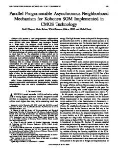
Fig. 3. Models divided by sections and intersections. (a) Apple model; (b) Greek head model.
The second part of the remeshing process is the application of the local mesh modification operators, until the mesh achieves good quality or the maximum number of iterations. For the parallel execution, this part can be divided into two steps: the preparation and the application of the local mesh modification operators. The preparation consists of a domain decomposition to produce mesh partitions depending on the number of processors. Kirk et al. in [6] use a standard non-overlapping domain decomposition in libMesh to achieve data distribution for parallel simulation of multi-scale, multi-physics applications using adaptive mesh refinement and coarsening strategies. The discrete domain is partitioned into a collection of sub-domains. The elements in each sub-domain are assigned to an individual processor. The two primary metrics in judging the quality of a partition are the sub-domain mesh size and the number of “edge cuts” in the resulting partition. For a mesh composed of a single type of element, each sub-domain should contain an equal number of elements so that the resulting domain decomposition is load balanced across all available processors. The edge cut metric, on the other hand, is designed to minimize the inter-processor communication required by the parallel solver. Seol and Shephard in [7] also use a non-overlapping domain decomposition. Here, only the sub-domain mesh size is considered, because the sections do not share points among them. The mesh partitions are formed by independent mesh sections and intersections. As one can see in Fig. 3, the red edges are the intersections and the other colors are the sections. The sections are at least two edges distance from each other. The same distance is applied to the intersections to guarantee that the modification in one section does not interfere in the other sections. The sections are improved in parallel and after that the intersections. The used data structure to store the mesh is the boundary representation (B-rep) first discussed in [8]. It represents a solid by segmenting its boundary into a finite number of bounded subsets. Each B-rep element of the model is formed by a set of other elements, following a hierarchy: the model is formed by a set of regions that are formed by a set of shells, that are formed by a set of faces that posses edges delimited by vertices. The B-rep is implemented such as a set of double-connected lists, i.e., the model has a list of regions, which each region has a list of shells and so on. Unfortunately, the double-connected lists directly represent the B-rep concept, but they are not thread-safe and the readers-writer lock paradigm is applied to guarantee safe access to the data structure. During the decision
Fig. 4. This flowchart presents the parallel method for improving the sections and after that the intersections.
of which, or if, the local mesh operator should be applied, just a reader permission is necessary. After the decision, to apply one of the operators, except the vertex relocation, the process must get writer permission and, consequently, block the other processors. To overcome this drawback the mesh data structure must be replaced by a thread-safe one, as the array-based half-edges presented by Alumbaugh and Jiao [9]. Considering that the modifications on one face only interfere to its neighbors and they are not being processed by other core, the replacement of the mesh data structure will permit a considerable improvement in processing time. The sections are remeshed by different processors as presented in Fig. 4 and, afterwards, the intersections are processed as well as the sections were. Algorithm 1 presents the remeshing process. V. RESULTS In order to compare the sequential remeshing algorithm and the parallel version, the speed-up was evaluated: , where is the execution time of the sequential algorithm and is the execution time of the parallel algorithm with processors.
NUNES et al.: A PARALLEL REMESHING METHOD
1205
20104 faces, 30156 edges, 10054 vertices. The speed-up was 1.22 in a machine with 2 processors. The speed-up in the first part is 1.6, which is also superior to the speed-up of the overall remeshing process. The Greek head model has smoother features than the shark model, however both resultant meshes (Figs. 5 and 6(b)) have its surface meshes in agreement with the initial model geometric characteristics and the requirements for a good finite element volumetric mesh generation. VI. CONCLUSION Fig. 5. Remeshed Greek head model.
An important goal of mesh generation is that the finite-element mesh should be formed by relatively well-shaped elements. Elements with small angles may degrade the quality of the numerical solution, because they can make the system of algebraic equations ill-conditioned and this compromises the solution accuracy. Another important goal is to obtain a high-quality finite-element mesh for electromagnetic simulation by FEM in a fair amount of time. The modified remeshing algorithm obtains improvements in the processing time, mainly during the step of generating the B-Spline patches that represents the smooth approximation of the model geometry. But, the overall gain is not as good as expected, because of the mesh data structure. This paper main contribution is the domain decomposition into independent mesh sections and intersections. The standard non-overlapping domain decomposition needs special care in the intersection areas. Therefore, if the mesh data structure is replaced by a thread-safe one, there would be no need for intercore communications, because modifications on one face only interfere to its neighbors. REFERENCES
Fig. 6. Shark model, (a) reconstructed surface from a points cloud, (b) remeshed model.
Fig. 5 shows the surface mesh of the Greek head model with improvements. The Greek head model has 16532 faces, 24798 edges, 8268 vertices. The overall speed-up was 1.24 in a machine with 2 processors and 1.31 with 8 processors. Considering only the step of generating the B-Spline patches that represents the smooth approximation of the model geometry the speedup went from 1.73 for 2 processors to 2.06 for 8 processors. The speed-up in the first part where very superior then the overall speed-up, because of the use of the readers-writer lock paradigm in the second part. When one processor needs to insert or remove an edge in the model, the other processors should wait until the task is done. A shark model is presented in Fig. 6, the first one 6(a) was downloaded from [4] and 6(b) represents the same model as before, but with an improved mesh. This mesh is formed by
[1] F. Mavriplis, “CFD in aerospace in the new millennium,” Can. Aer. Space J., vol. 46, no. 4, pp. 167–176, Dec. 2000. [2] C. R. S. Nunes, R. C. Mesquita, and D. A. Lowther, “Remeshing driven by smooth surface approximation of mesh nodes,” IEEE Trans. Magn., vol. 43, pp. 1541–1544, Apr. 2007. [3] N. Amenta, S. Choi, and R. Kolluri, “The power crust, unions of balls, and the medial axis transform,” Comput. Geom.: Theory Applicat., vol. 19, no. 2–3, pp. 127–153, 2001. [4] AIM@SHAPE, Aim@shape Shape Repository v4.0 2010 [Online]. Available: http://shapes.aim-at-shape.net/ [5] V. Surazhsky and C. Gotsman, “Explicit surface remeshing,” in Proc. Eurographics Symp. on Geometry Processing, Aachen, Germany, Jun. 2003, pp. 17–28. [6] B. S. Kirk, J. W. Peterson, R. H. Stogner, and G. F. Carey, “Libmesh: A c++ library for parallel adaptive mesh refinement/coarsening simulations,” Eng. Comput., vol. 22, pp. 237–254, 2006. [7] E. S. Seol and M. S. Shephard, “Efficient distributed mesh data structure for parallel automated adaptive analysis,” Eng. Comput., vol. 22, no. 3, pp. 197–213, 2006. [8] A. L. C. C. Magalhães and R. C. Mesquita, “Exploring inner boundaries in solid modelers applied to electromagnetic problems,” IEEE Trans. Magn., pp. 1682–1686, Jul. 2000. [9] T. J. Alumbaugh and X. Jiao, “Compact array-based mesh data structures,” in Proc. 14th Int. Meshing Roundtable, San Diego, CA, Sep. 2005, pp. 485–504.