to a parallel platform where all the joints are actuated except for the platform .... directed from the contact point to the center of mass of the object, and the other ...
2013 IEEE International Conference on Robotics and Automation (ICRA) Karlsruhe, Germany, May 6-10, 2013
A Parallel Robots Framework to Study Precision Grasping and Dexterous Manipulation Júlia Borràs, Member, IEEE, and Aaron M. Dollar, Member, IEEE
Abstract— Dexterous, within-hand manipulation, in which an object generally held in the fingertips is manipulated by the fingers, shares many similarities to parallel robot configurations. This paper shows how to apply a mathematical framework commonly used for parallel robots to study the kinetostatic properties of hands manipulating objects using precision grasps, considering compliance and underactuation in the joints, without requiring the use of the grasp matrix. The proposed framework is suitable for any hand, but we focus on underactuated hands. We show how the natural redundancy present in fully-actuated hands can be eliminated using underactuation, leading to simplified non-redundant systems that are easier to control. We primarily focus our efforts on introducing and describing the theoretical framework, and follow this with an example application using a three-fingered underactuated hand. For this example, we define the feasible workspace as the subspace of the kinematic workspace for which the hand can accomplish a grasp, and we study how the compliance, rest angles, and joint coupling in the fingers can be designed to increase the size of this feasible workspace.
I. INTRODUCTION Analyzing dexterous manipulation with multi-fingered hands is challenging, in part due to the difficulties in dealing with the closed-loop kinematic chain established between the fingers and objects and the potential for an overconstrained system. This paper revisits a mathematical framework usually used with parallel platforms for the study of robotic multifingered hands performing dexterous, within-hand manipulations (Fig. 1). In particular, we propose the formulation to handle multifingered hands manipulating rigid objects within a precision fingertip grasp, using a point contact with friction, or hardfinger model [1, 2]. We show that the proposed parallel robots framework can be applied to study the static properties of a hand holding an object, provided that we restrict the analysis only to those configurations of the workspace for which the fingertip forces are within their respective friction cones. A secondary point of this paper is to show the feasibility of using underactuated hands for dexterous manipulation. Usually parallel robots use as many joint actuators as degrees of freedom (DoF) the platform has to move. Even though each leg itself has usually as many DoFs as platform DoFs, only one or two of the joints per leg are actuated, called active joints, and the rest are left free to move. This simplifies the control of the resulting mechanism, as the free moving This work was supported in part by the National Science Foundation, grant IIS-0952856. J. Borràs and A. M. Dollar are with the Department of Mechanical Engineering and Materials Science, Yale University, New Haven, CT USA. (e-mail: {julia.borrassol, aaron.dollar}@yale.edu).
978-1-4673-5642-8/13/$31.00 ©2013 IEEE
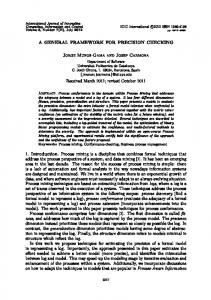
Fig. 1. When an open hand is closed to grasp an object, the kinematic structure is equivalent to a parallel robot.
joints automatically adapt convenient configurations to hold the kinematic constraints. On the contrary, robotic hands need to have most of the joints of the fingers actuated, to be able to be articulated and avoid collapsing under their own weight before contact with an object. Thus, when holding an object, they are equivalent to a parallel platform where all the joints are actuated except for the platform attachments (i.e. finger contacts). This results in a redundantly actuated parallel manipulator [3]. Adding one or two degrees of redundancy is sometimes used in parallel manipulators to reduce singularities and to increase the usable workspace [4]. However, highly redundant configurations have substantial drawbacks such as errors due to internal forces that complicate the calibration, overconstrained systems, and a complex control process. This issue can be solved using underactuated fingers. Underactuated fingers typically use one actuator to control two or more joints of a finger, so that all the joints are active but are coupled together through some sort of differential mechanism [5]. The coupling can be implemented through cables and pulleys or linkages [5-8] , and generally require one or more compliant elements to provide a loose constraint on the unconstrained DoFs and/or provide a means of antagonistic actuation to the tendon. In [9] we showed how to use compliant joints with the usual framework for parallel manipulators (without dealing with underactuation or fingertip constraints).
1587
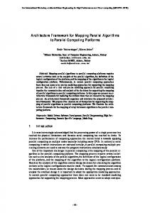
Fig. 2. Example configurations with fingertip forces inside the friction cones (top) and outside them (bottom).
This work focuses on the static analysis of hands holding objects in a precision grasp, analyzing the conditions under which the fingertip forces are inside the friction cones and therefore the grasp belongs to the feasible workspace of the hand/object system. We show some preliminary results for a given example using the proposed framework, showing the resulting workspaces and some basic tools for the design of a set of convenient compliant parameters. The study of the stiffness matrix and dynamic properties using the same framework are left out of the scope of the work. In Section II we start introducing the mathematical framework that is commonly used in the parallel robots literature [10, 11], adapting it to the analysis of an underactuated robotic hand and defining how the friction cone conditions are applied under the new framework. In Section III we focus on an underactuated hand example, showing the workspaces of the hand grasping the object for different parameters and some preliminary tools to explore how to enlarge such workspaces. Finally, Section IV discusses the results and the future work on the topic. II. PARALLEL ROBOTS FRAMEWORK A hand manipulating an object using the hard-finger contact model is equivalent to a parallel manipulator where the platform/object attachments are spherical joints with the
additional constraint that the contact force is within the friction cone. We assume that such parallel manipulator is redundantly actuated. For the kinematic model, we consider all the joints as independently actuated, even if they are coupled and controlled by the same motor. Let n be the DoFs in which the grasped object can be moved, � � 6, and let � � ��� , … , �� be all the joints in all the fingers. Any value of � determines a configuration of the hand, but when manipulating the object, the only feasible configurations are those that satisfy the kinematic constraints, namely, a set of equations that can be written as �� � 0. These are normally distance constraints between the fingertips, that must remain constant, assuming that the object is rigid enough and that the hand does not re-grasp the object. We define the kinematic configuration space of the hand holding the object as (1) � � � � ∈ �� | �� � 0� The position and orientation of the object are defined by an element of SE(3), in our case, a position vector � and a rotation matrix �. For any feasible configuration, we can compute the position and orientation of the object solving the loop equations, which can be defined by requiring the fingertip coordinates and the object contact coordinates to be coincident. We can write the solution of the loop equation as the map ��: � → ���3 , usually known as forward kinematic problem. The kinematic workspace of the manipulated object is then defined as (2) �� � ����� | � ∈ � � ⊂ ���3 The static analysis of the system is done through the Jacobian matrix that relates the torques on the active joints with the resulting transmitted wrench at the object. It can be computed using screw theory considering all joints as active except the object attachments, which are considered spherical joints free to move. The Jacobian matrix using screw theory can be obtained following the steps proposed in Chapter 5.6 in [11]. Using the hard-finger contact model and the theory of reciprocal screws one can obtain a � ! " Jacobian matrix and we can write the static system as (3) # � $% & where & � �'( , for ) � 1, … , ", is the vector of torques done by each joint i and # is the resulting output wrench on the object. The advantage of the screw Jacobian is that is has a direct interpretation in terms of the geometry of the mechanism; this fact has been applied in the parallel robot literature for easier detection of singularities and as a tool for optimal design. This system has the same behavior as a hand, provided that we discard those configurations for which the resulting fingertip forces are outside the friction cone, as will be detailed in section B (see Fig. 2 for an example of fingertip forces inside and outside the friction cones). Static equilibrium occurs when the external applied forces are + � ,#. If static equilibrium can be achieved for any +, then the grasp is called force closure grasp [1]. Finally, we also want to consider compliance in the joints. We follow the model proposed in [9, 12]. Each torque '( will be composed of two components, one from the actuator torque and one from the spring torque, obtained using the Hooke’s law. This is '( � -'( . �( ��( , /( , (4)
1588
where �( is the spring stiffness constant and /( is the resting configuration of the spring. We are assuming that all joints are rotational joints, so that �( are angles and the springs are torsional springs, but the same can be done with prismatic actuators and linear springs. Substituting equation (4) in equation (3) leads to a system in the form # � $0 -& . $0 1&, (5) where we have split the torques vector into the actuator torques -& � � -'( and the compliant torques 1& � ��( ��( , /( . Note that, for a given configuration and a given external applied force, the system in (5) is a linear system of � equations, where the unknowns are the m actuation torques, � < ". If the matrix $0 is full rank, the system in (5) has a (" , �)-dimensional set of solutions. A single solution can be chosen optimizing for example the maximum actuation torque to be as small as possible, constrained that the resulting fingertip forces are inside the friction cones. A. Underactuated hands When using underactuated fingers, some of the actuators control two or more of the joints. This translates into coupled torques between the joints actuated by the same motor. When the actuation is done by pulling cables, such coupling depends only on the ratio between the radii of the rotational joints, that will be called the transmission ratio 3 [8]. Let us assume that we introduce as many couplings as necessary to have only n actuators (where � are the DoFs of the object). In other words, from the previous " independent actuator torques, only � are linearly independent, named -&4 � � -'( ) for ) � 1, … , �, and the remaining " , � are related to one of the -'( through a transmission ratio 35 , that is, -'5 � 35 -'( for 6 � 1, … , " , �. Then, we can rewrite equation (5) as # � $0- -&4 . $0 1& (6) where &4 is the n-dimensional vector that contains only the independent actuation torques. The matrix $0- is a � ! � square matrix that can be obtained from $0 using linear combinations of the columns with the scaling factors 35 . See section III for an example. For a given configuration and a given external applied force, this system is a square linear system where the unknowns are the � actuation torques. In this case, there is a unique solution for each configuration. Note that for a redundantly actuated system (i.e., a fullyactuated hand) the matrix in (5) is � ! " with � < ". When using underactuation, this matrix is � ! �, and thus, the dimension of the singularity space is a (m-1)-dimensional subspace of �, for which det�$0- � 0. For the � ! " matrix, the dimension of the singularity space is lower [4] This means that an underactuated hand will have, in general, a smaller workspace as more configurations will be close to singularities. However, with improved design processes, the workspace can be large enough for the required tasks. Thus, underactuation is a promising feature for the design of hands with more efficient manipulation processes, in contrast to fully actuated hands, as the forward static problem is much simpler, resulting in simpler dynamics and control processes.
In Section III we will study how the spring resting lengths, stiffness constants and the transmission ratio play an important role on the maximization of the size of the usable workspace. B. Fingertip forces and friction cone conditions. We already mentioned that the parallel robots mathematical framework can be applied to hands as long as the fingertip forces are constrained to be inside the friction cones. In this section we describe how can we write such conditions in a natural way using the proposed framework. Let us assume that the object has 6 degrees of freedom (� � 6) and the hand has l equal fingers with s joints each (so, the number of joints is " � :;). From equation (3), consider the " columns of the Jacobian matrix as $0 � ? for ) � 1, … , : and @ � 1, … , ;. Each column has the form 0 $(> � , B(> ? , where A(> corresponds to the force the joint j transmits to the fingertip of the finger i, with magnitude '(> , and "(> its corresponding moment. Then, we can write the wrenches at the fingertips as '(� (7) #( � �$(� , … , $(C D ⋮ F, for ) � 1, … , :. '(C
In other words, the fingertip wrench can be written as #( � �+( , G( , where the fingertip force will be given by +( � '(� A(� . ⋯ . '(C A(C (see Fig. 4 for an example). The other 3 components correspond to the moment done by +( , G( � I( ! +( . The sum of all the fingertip forces and moments is the resulting output force and moment on the object1. According to the grasping framework, using the hardfinger contact model, the fingertip forces, not the moments, are computed through a different Jacobian matrix that is composed of the serial chain Jacobian of each finger. The computation of the resultant force and moment is done through the grasping matrix G. We obtain the fingertip forces and the resultant output wrench directly using only the Jacobian matrix introduced in equation (3). The friction cone is usually defined with respect to the coordinate frame attached to the contact point, whose axes are defined as J( � �K( , L( , M( �, where K( is the unit vector directed from the contact point to the center of mass of the object, and the other two are defined orthogonal unit vectors [1]. With our framework, we only need to define the first vector, which can be easily obtained as K( � � , I( , being � the position vector of the object with respect to the palm and I( the contact point. Then, we split the fingertip force +( into the projection on K( , given by N�( � K0( +( , and the projection on the normal plane to the vector, ⊥ �( � || �OP , K0( KQ +( ||. The fingertip is inside the friction cone as long as ⊥ (8) �( � R N�( , where R represents the amplitude of the friction cone which will be assumed to be 0.7 for the simulations in Section III. Fig. 2 shows two example configurations for an applied force of + � �0,0, ,1 , with friction cones with R � 0.7.
1
1589
All the coordinates are with respect to the palm reference frame.
where
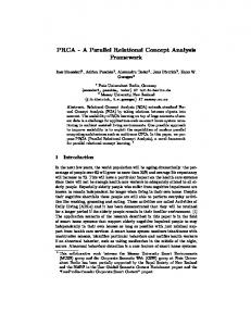
Fig. 3. Kinematic model of the studied hand. The center points of the base joints are equally distributed around a circumference of diameter UV , and the contact points around a circumference of diameter UW .
At a given configuration, the expression of the fingertip forces depend only on the torques of the joints at each finger, which depend on the actuation torques and on the spring parameters. If the force is outside the friction cone, the configuration is considered out of the feasible workspace. Thus, modifying the spring parameters can increase the range of fingertip forces that remain inside the friction cones, and thus, can enlarge the workspace. III. DESIGN PARAMETERS FOR A 3-URS HAND In this section we show how to select the compliant parameters to increase the volume of the workspace. To enlighten readability and simplify notation, we apply the framework to a three-fingered hand where each finger has three rotational joints (see Figs. 1 and 3). This architecture is similar to multiple underactuated hands such as the Barrett hand [13] or the JPL hand [14]. We assume the object is circular with diameter UX and the contact points are uniformly distributed around it. The fixed reference frame is located at the center of the palm and the mobile frame centered at the center of mass of the object. Without loss of generality, we can write the coordinates of the palm attachments and the contact points with respect to Z( and I4( , respectively, with the local reference frames as Y zero z coordinate (Fig. 3). The position and orientation of the object with respect to the palm reference frame are given by a position vector � ∈ �[ and a rotation matrix � ∈ �\�3 . Then, the coordinates of the attachments with respect to the palm Z( and reference frame are Y( � Y (9) I( � � . � I4( . As we assume contact, the coordinates of the contact points are the same as the coordinates of the fingertips, which can be parameterized following the steps in Chapter 2.2 of [15]. Such coordinates can be expressed as I( � Y( . ]( �0,0,1 0 . ^( �cos��(� , sin��(� , 0 0 , (10)
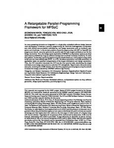
]( � :( sin��(d . e( sin��(d . �([ , (11) ^( � :( cos��(d . e( cos��(d . �([ , and :( and e( are the lengths of the proximal and distal links of the ith finger, respectively. We can obtain a similar parameterization of the distal joint centers (f( in Fig. 3). Alternatively, a similar parameterization can be obtained using Denavit-Hartenberg parameters [16]. The inverse and forward kinematics can be obtained by solving the system resulting from equating equations (9) and (10). When holding the object, each finger always stays in a specific assembly mode of the corresponding serial chain, so that we can solve the forward kinematics function ���� and the inverse kinematics g���, � in a single closed form solution. The kinematic constraints are given by the system d h ? � 3JXd , ) i @j. Considering all joints of the fingers actuated, the Jacobian in equation (3) is the 6!9 matrix $0 � �$�� $�d $�[ $d� $dd $d[ $[� $[d $[[ , where $(> is the screw corresponding to the action of the joint j of the finger i with expressions ,1 $(� � � l( , I( ! l( , ^( 1 (12) $(d � � I , f( , I( ! �I( , f( ln e( sin��([ ( ,1 $([ � �I , Y( , I( ! �I( , Y( ln e( sin��([ ( where ^( is defined in equation (11) and l( � �sin��(� , , cos��(� , 0 is the axis of rotation of the 2nd and 3rd joints of the finger i. See Fig. 4 for a graphical representation of those screws. This is the main difference from the usual framework used for hands. These 3 screws at each finger will define the fingertip wrench as '(� $(� . '(d $(d . '([ $([ . We consider a pulling cable that controls the 2nd and the 3rd joints, so that their corresponding torques are '(d � 3d o and '([ � 3[ o where o is the tension of the cable and 3> are the radii of the corresponding joints (equal for all fingers). p For simplicity, we can write '([ � q '(d � 3'(d , where 3 is pr
the transmission ratio. Then, $0- in equation (6) is a 6 ! 6 matrix that can be obtained from $0 as (13) $0- � �$(� , $(d . 3$([ , ) � 1,2,3, and the vector of actuation torques is & � �'�� , '�d , 'd� , 'dd , '[� , '[d 0 . Note that the magnitude of the tension force exerted by the cable is given by o � '(d /3d . All the simulations were run in Mathematica 8 (Wolfram Research Inc., Champaign, IL), for a hand with palm diameter UV � 2, an object of diameter UX � 0.75 and the dimensions of the finger links :( � 1 and e( � 0.667, for ) � 1,2,32. A. Kinematic workspace vs. feasible workspace We obtain a representation of the kinematic workspace by sweeping the 6 dimensional space SO(3) represented by the three translational parameters �vw , vx , vy and the three rotational parameters, yaw, pitch and roll angles �z, {, | that
1590
2
Consider all international units.
A configuration will be considered part of the feasible workspace if the actuation torques of the coupled joints are positive and the fingertip forces are inside the friction cones (Fig. 2 - top). Note that our feasible workspaces are composed of configurations in static equilibrium for a given external force, not for any possible external force. Changing the parameters for the springs and the transmission ratio between the torques can change the size of the feasible workspace significantly. Fig. 6 shows the feasible workspace using the springs parameters and the transmission ratio of the hand used in [18], K d � 0.5, K [ � 2, δd � 0, δ[ � 0, 3 � 1, (14) and for a given applied force of + � �0,0, ,1,0,0,0 , we obtain that the graspable workspace is a 21.38% of the position kinematic workspace and a 27.67% of the orientation one.
Fig. 4. Force transmitted to the fingertip under the torque exerted for each joint for the three actuated joints in each finger. The expression of the fingertip force is given by '(� A(� . '(d A(d . '([ A([.
give the rotation matrix � � �y �z �x �{ �w �| , solving the forward kinematics at each step and discarding any non-real solution. Representing a 6 dimensional space is difficult, for that reason, we show results for an orientation workspace and a position workspace, corresponding respectively to the slices of the workspace with a fixed position �v � �0,0,1.15 , Jy � 0�, and the slice with a fix orientation �Jy � 0, Jx � 0, Jw � 0�. In Fig. 5 we show a representation of both kinematic workspaces. For the orientation workspace (Fig. 5 – Left) each point represents the direction of the vector normal to the plane formed by the 3 contact points, and for the position workspace (Fig. 5-right), each point corresponds to the coordinates of the center of mass of the object. We consider as an applied external force the weight of the object, � � �0,0, ,1,0,0,0 and compliance only in the underactuated joints, which means that the compliant torque corresponding to the first joints is 1'(� � 0 and the rest, 1 '(d � ,�d ��(d , /d and 1'([ � ,�[ ��([ , /[ , which depend on 4 parameters ��d , �[ , /d , /[ � For each configuration, we can solve the system in equation (6) for -&, and then compute the corresponding fingertip forces. In addition, we consider an underactuated hand with only one pulling cable per finger that can exert only positive or negative torques depending on the chosen routing of the cable. We assume only positive torques; so that the springs tend to open the hand and the cables will act to close it. That mechanism is known in prosthetics as an activeclose or voluntary-close device [17]. Considering only negative actuator torques would lead to an active-open device.
B. Design exploration For a given fixed kinematic workspace, the size of the feasible workspace can change depending on the spring parameters and the transmission ratio between the torques, r. To obtain larger workspaces we propose a simple preliminary procedure. As the workspace and the hand are symmetric around each finger, we divide the workspace in thirds. For a third of the workspace, we sample a uniformly distributed portion of the configurations. For a given external force of � � �0,0, ,1,0,0 , we explore all possible combinations of parameters, stiffness constants ranging from 0 to 3, resting angles from 0 to , and the transmission ratio from 0.1 to 3 d for r. We chose all those combinations of parameters that give the maximum number of feasible configurations. And from those, we chose the one for which the overall torque, expressed as the sum of the absolute values of the actuation torques, is minimum. We run the process separately for the position and orientation workspaces. Fig. 7 shows the results. With the new parameters, the orientation workspace is 87.20% larger than before and the position workspace 47.75% larger. The chosen parameters for the orientation workspace are K d � 0.45, K [ � 2.38, δd � 0.11, δ[ � 0, (15) 3 � 0.63,
1591
(a)
(b)
Fig. 5. (a) Kinematic orientation workspace. Each dot on the sphere represents the direction of the vector normal to the plane formed by the 3 contact points. (b) Kinematic position workspace. Each dot represents the position vector of the center of mass of the object.
Fig. 7. Feasible workspaces for orientation and position with the chosen parameters given in equations (15) and (16), respectively. As in Fig. 6, color represent the value of the maximum actuation torque, where minimum and maximum values are given under the gradient color bar for each workspace.
Fig. 6. Colored regions represent configurations with a feasible grasp, using the parameters of the hand in equation (14). The colors correspond to the value of the maximum actuation torque, from lightest color (lowest value) to darkest (highest value). The minimum and maximum values are given under the bottom gradient color bars for each workspace.
and for the position workspace K d � 0.02, K [ � 2.56, δd � 1.33, δ[ � 0, (16) 3 � 2.57. Note the large difference between the transmission ratios. For large orientation ranges, a small transmission ratio is better, while better results for translation ranges are obtained with larger transmission ratio. C. Manipulability indexes Many efforts have been put in finding an appropriate index that characterizes the behavior of a manipulator through the workspace. Those indexes are usually ratios between directions in the input joint space and the output task space. In the robotic hands literature like [19, 20] the indexes are based on serial chains manipulability indexes initially defined in [14, 21], as each finger is a serial chain and they all collaborate. In the parallel robots literature manipulability indexes have also been widely studied, generally by adapting the indexes proposed for serial chains to parallel robots. But J.P. Merlet showed in [22] that most of those indexes are not very consistent for the study of parallel robots performance. When it comes to study the ratios between the magnitude of the input torques and the corresponding magnitudes of the output generated force, Merlet showed that the determinant of the Jacobian matrix is usually good enough, as both magnitudes are related through the solution of the linear system in equation (3), which defines the limits of the usable workspace [23]. For underactuated hands, that linear system is a bit more involved because the solution of the system not only depends on the determinant of the matrix of the system, $0- in equation (6), but also on the extra term given by the springs, that is related with the matrix $0 . In Fig. 8 we show the relationship between the medium value of the actuation torques and the determinant of the matrix $0- for all the configurations of the position and the orientation workspaces shown in Fig. 7. In other words, each point in Fig. 8 corresponds to a single configuration (and its color is related to the magnitude of the coordinate of its position vector). For the lighter colors, the graphic shows larger mean torques as the value of the determinant is closer
to zero, as expected. As the z coordinate of the position of the platforms decreases, the expected relation between both magnitudes changes due to the effect of the compliance in the joints, as the lower is the z, the farther away are the springs from their resting configurations. These results show that when considering compliance, the Jacobian matrix determinant as a performance index may not be useful as expected, but future research should be done to study other indexes related with the matrix in relation to the direction of the fingertip forces. A lot of effort is done lately in the parallel robots field to find an appropriate index to measure the performance of the robots. A comparison between the indexes proposed for robotic hands and for parallel robots is left for future work. IV. DISCUSSION AND FUTURE WORK We have shown how to use the screw Jacobian matrix framework for the study of the kinetostatics of a robotic hand while it is performing a precision grasp and dexterous withinhand manipulation. The presented approach does not use the grasp matrix but directly a Jacobian matrix that has a neat geometric interpretation. In this context, underactuated hands are proven to be the equivalent to non-redundant parallel
1592
Fig. 8. Cross relation between the mean of the absolute value of the actuation torques and the value of the determinant of the matrix -0 , for all the configurations in the orientation and the position workspace plotted in Fig. 7. Darker colors correspond to lower z coordinate position of the object at each configuration.
robots, making them a promising direction for dexterous manipulators, suitable both for grasping and for an easier controllable manipulation in contrast with the typical fully actuated hands. The theoretical framework has been successfully applied to a three-fingered hand example, considering underactuation using a single cable per finger, as an active closing device. With a simple exploration of the parameter values, we have been able to significantly increase the workspaces from an initial set of values taken from an implemented hand. Future work will explore how to maximize the workspace size for any possible applied external force. The considerably different transmission ratios obtained for orientation versus position workspaces envisage a challenge for an optimal design. The orientation workspace has special interest for robotic hands, as both the position and the rotation around the axis can often be provided by the arm and the wrist, but a rotation with respect to the axes x and y of the object are more difficult to achieve. In that sense, it may be more advantageous to prioritize the optimization of the orientation workspace. However, there are many possible situations in which the position workspace may be desired, such as for fine manipulation tasks. For future research in the topic, it will be interesting to perform a more thorough investigation of the design tradeoffs of different hand parameters, including testing results considering a greater range of joint torque, external forces and coupling parameters (e.g. positive and negative), different link lengths, and stiffnesses. We would also like to investigate an index that relates to the Jacobian matrix with the condition of the fingertip forces to be inside the friction cone for an easier optimization of workspaces. Finally, it would be interesting to study if other contact models like the soft-finger can be modeled with parallel manipulators with a different type of joints as platform attachments.
[12] C. Quennouelle and C. m. Gosselin, "A Quasi-Static Model for Planar Compliant Parallel Mechanisms," Journal of Mechanisms and Robotics, vol. 1, p. 021012, 2009. [13] W. Townsend, "The BarrettHand grasper – programmably flexible part handling and assembly," Industrial Robot: An International Journal, vol. 27, pp. 181-188, 2000. [14] J. K. Salisbury and J. J. Craig, "Articulated Hands: Force Control and Kinematic Issues," The International Journal of Robotics Research, vol. 1, pp. 4-17, 1982. [15] R. M. Murray, Z. Li, and S. S. Sastry, A mathematical introduction to robotic manipulation: CRC Press, Inc., 1994. [16] J. Denavit and R. S. Hartenberg, "A kinematic notation for lower-pair mechanisms based on matrices," ASME Journal of Applied Mechanics, vol. 23, pp. 215-221, 1955. [17] G. Smit and D. H. Plettenburg, "Efficiency of voluntary closing hand and hook prostheses," Prosthetics and Orthotics International, vol. 34, pp. 411-427, 2010. [18] L. U. Odhner, R. R. Ma, and A. M. Dollar, "Precision Grasping and Manipulation of Small Objects from Flat Surfaces using Underactuated Fingers," in IEEE International Conference on Robotics and Automation, 2012, pp. 2830 - 2835 [19] A. Bicchi and D. Prattichizzo, "Manipulability of Cooperating Robots with Unactuated Joints and Closed-Chain Mechanisms," IEEE Transactions on Robotics and Automation, vol. 16, pp. 336-345, 2000. [20] D. Prattichizzo, M. Malvezzi, M. Gabiccini, and A. Bicchi, "On the manipulability ellipsoids of underactuated robotic hands with compliance," Robotics and Autonomous Systems, vol. 60, pp. 337-346, 2012. [21] T. Yoshikawa, "Manipulability of Robotic Mechanisms," The International Journal of Robotics Research, vol. 4, pp. 3-9, 1985. [22] J. P. Merlet, "Jacobian, Manipulability, Condition Number, and Accuracy of Parallel Robots," Journal of Mechanical Design, vol. 128, pp. 199-206, 2006. [23] J. Hubert and J. P. Merlet, "Singularity Analysis through Static Analysis," in Advances in Robot Kinematics, 2004, pp. 13-20.
REFERENCES [1]
D. Prattichizzo and J. C. Trinkle, "Grasping," in Springer Handbook of Robotics, B. Siciliano and O. Khatib, Eds., ed: Springer-Verlag, 2008, pp. 671-700. [2] J. Kerr and B. Roth, "Analysis of Multifingered Hands," The International Journal of Robotics Research, vol. 4, pp. 3-17, 1986. [3] A. Müller, "Redundant Actuation of Parallel Manipulators," in Parallel Manipulators, towards New Applications, H. Wu, Ed., ed: I-Tech Education and Publishing, 2008. [4] B. Dasgupta and T. S. Mruthyunjaya, "Force redundancy in parallel manipulators: Theory and practical issues," Mechanism and Machine Theory, vol. 33, pp. 727-742, 1998. [5] L. Birglen, T. Laliberte, and C. Gosselin, Underactuated Robotic Hands: Springer, 2008. [6] S. Hirose and Y. Umeteni, "The Development of Soft Gripper for the Versatile Robot Hand," Mechanism and Machine Theory, vol. 13, pp. 351-359, 1978. [7] A. M. Dollar and R. D. Howe, "The Highly Adaptive SDM Hand: Design and Performance Evaluation," The International Journal of Robotics Research, vol. 29, pp. 585-597, 2010. [8] R. Balasubramanian, J. T. Belter, and A. M. Dollar, "Disturbance Response of Two-Link Underactuated Serial-Link Chains," Journal of Mechanisms and Robotics, vol. 4, p. 021013, 2012. [9] J. Borràs and A. M. Dollar, "Static analysis of parallel robots with compliant joints for in-hand manipulation," in International Conference on Intelligent Robots and Systems, Portugal, 2012. [10] J. P. Merlet, Parallel robots, Second edition ed.: Springer, 2006. [11] L.-W. Tsai, Robot Analysis. The mechanics of serial and parallel manipulators.: John Wiley & sons, Inc., 1999.
1593