A passive RGBD sensor for accurate and real-time depth sensing self-contained into an FPGA Stefano Mattoccia
Matteo Poggi
Dept. of Computer Science and Engineering University of Bologna, Italy Viale Risorgimento, 2 40136 Bologna
Dept. of Computer Science and Engineering University of Bologna, Italy Viale Risorgimento, 2 40136 Bologna
[email protected]
[email protected]
ABSTRACT
VGA resolution in indoor environments. Other remarkable technologies in this category are Time of Flight (ToF) and LIDAR. These latter devices infer depth by measuring the time required for sensing a bounced signal (coded light or laser). RGBD sensors based on active technologies are, in most cases, quite accurate but have in some circumstances strong limitations. In fact, they may interfere with each other, are ill-suited to environments flooded with sunlight (e.g, ToF and Kinect) and may be cumbersome or with mechanical parts (e.g., LIDAR). Devices based on passive technology have the potential to overcome the before mentioned issues. Passive stereo vision, in particular, is a well-known approach [12], based on standard imaging sensors, to infer depth by identifying corresponding points on two or more images. In stereo vision the algorithm to deal with the so called correspondence problem plays a major role in terms of computational requirements and effectiveness for the overall technology. Although it may provide unreliable results when dealing with ambiguous image patterns (e.g., in poorly textured regions), compared to active technologies, it is well suited to indoor and outdoor environments. Due to the many applications that can take advantage of pointcloud data provided by a passive sensor, passive stereo vision is a very active research area [12] and in recent years several improvements have been proposed. In this field the Semi Global Matching algorithm (SGM) [8] is very popular due to its accuracy and efficiency. Nevertheless, due to its demanding computational requirements for realtime depth sensing, many different computing architectures (e.g., CPUs, GPUs, DSPs, FPGAs, ASICs, etc.) have been adopted [17]. Systems based on standard CPUs [4] or GPUs [1] are typically not well-suited to consumer/embedded applications due to high power requirements, cost, and size. Low power and massively parallel devices such as FPGAs have attracted the interest of many researchers working in this field in order to obtain optimal performance/Watt. These devices can be configured by means of hardware description languages (HDLs), such as VHDL or Verilog, or High Level Synthesis (HLS) tools. Examples of stereo vision algorithms mapped into FPGAs are reported in [2, 5, 15, 13, 10, 18, 14]. In this paper we describe the design of an RGBD sensor based on this technology that relies on a simple and cheap computing architecture and state-of-the-art visual processing pipeline. Our proposal allows us to obtain accurate and dense depth maps in real-time with small power consumption, weight and size.
In this paper we describe the strategy adopted to design, from scratch, an embedded RGBD sensor for accurate and dense depth perception on a low-cost FPGA. This device infers, at more than 30 Hz, dense depth maps according to a state-of-the-art stereo vision processing pipeline entirely mapped into the FPGA without buffering partial results on external memories. The strategy outlined in this paper enables accurate depth computation with a low latency and a simple hardware design. On the other hand, it poses major constraints to the computing structure of the algorithms that fit with this simplified architecture and thus, in this paper, we discuss the solutions devised to overcome these issues. We report experimental results concerned with practical application scenarios in which the proposed RGBD sensor provides accurate and real-time depth sensing suited for the embedded vision domain.
CCS Concepts •Computer systems organization → Embedded systems;
Keywords stereo vision, FPGA, RGBD, embedded, real-time
1.
INTRODUCTION AND RELATED WORK
RGBD sensors providing monochrome or color image and accurate dense depth maps, are crucial to improve the effectiveness of several computer vision applications. This fact has lead to the development of different technologies, broadly categorized in active and passive. Active sensors infer depth data by perturbing the sensed scene according to different approaches. A representative example of this category is the Microsoft Kinect 1, a cheap, yet accurate, device projecting a structured light pattern, by means of an infrared projector, sensed by an infrared imaging sensor. It enables to infer accurate depth maps and images at Permission to make digital or hard copies of all or part of this work for personal or classroom use is granted without fee provided that copies are not made or distributed for profit or commercial advantage and that copies bear this notice and the full citation on the first page. Copyrights for components of this work owned by others than ACM must be honored. Abstracting with credit is permitted. To copy otherwise, or republish, to post on servers or to redistribute to lists, requires prior specific permission and/or a fee. Request permissions from
[email protected].
ICDSC ’15, September 08 - 11, 2015, Seville, Spain c 2015 ACM. ISBN 978-1-4503-3681-9/15/09. . . $15.00
DOI: http://dx.doi.org/10.1145/2789116.2789148
146
implemented into the FPGA, the deserializer, extracts synchronized stereo pairs from the incoming high-speed LVDS stream. With a pixel frequency of 24 MHz the LVDS stereo stream is clocked at 432 MHz (i.e., 18X, in order to encode, in the same time, 8 + 8 bit for the two pixels plus a start bit and a stop bit). Of course, the LVDS setup adopted, compared to a simple parallel transmission, requires a more complex front-end to extract the image pixels and also leads to a slightly increased power consumption. On the other hand, this solution allows us to put the stereo-head up to 5 m from the computing platform and hence enables to better customize the hardware setup according to specific application requirements. Once completed the deserialization phase within the FPGA, the visual processing pipeline executes the following tasks before sending the out its outcome to the host computer via the USB interface; image rectification, census transform, stereo matching and filtering outliers. Figure 1: Left) Main functional components of the RGBD sensor. - Right) Optionally stackable PCBs. The stereo head in this configuration has a baseline of 6.6 cm.
2.
3.
HARDWARE DESIGN CONSTRAINTS
The hardware design outlined in the previous section induces major constraints to the computational structure of the visual processing pipeline. In fact, the whole memory available for buffering partial results consists of the blockrams (BRAM), look-up-tables (LUT) and flip-flops (FF) available inside the FPGA. For instance, the FPGA models adopted in our design have BRAMs, the largest amount of memory inside the reconfigurable logic, of about 300 KB. Therefore it would not be enough to store an entire frame at VGA resolution (about 300 KB). Moreover, another issue is concerned with image rectification that requires, for undistortion tables, an additional amount of memory multiple of the image size. Finally, a further problem related to the missing external memory is concerned with frame buffering that, for the same reasons outlined before, is not enough to handle the whole output of the visual processing pipeline (e.g, 16 bit disparity map, left and right original or rectified stereo pair). For each of the issues highlighted so far we have adopted appropriate methodologies, described in the next sections , aimed at obtaining a good trade-off between hardware resources and depth sensing accuracy.
ARCHITECTURE OF THE 3D SENSOR
Our design goal was aimed at developing, from scratch, an effective 3D sensor based on stereo vision technology suited for embedded applications. In particular, major constraints in our design were concerned with depth maps accuracy, low latency, reduced power consumption, low weight and size. Moreover, we also were interested in a simplified and low cost hardware design basically made of two imaging sensors, a low-cost FPGA and a communication controller. To further simplify the hardware design, we considered the opportunity to avoid external memory devices and, after a thorough evaluation, we decided to adopt this solution. This yielded a significant simplification to the hardware design at the expense, on the other hand, of an increased effort for algorithm implementation, mostly required to devise solutions suited to the small memory available inside the FPGA. Regarding the reconfigurable device, we adopted the Spartan 6 LX family focusing in particular on models 45, 75 and 100. The main functional components of our hardware design are outlined on the left of Figure 1: the stereo head, the modules implemented into the FPGA and a USB controller (Cypress FX2). The stereo head is based on two Aptina mt9v034 sensors (monochrome or color, WVGA resolution at 60 fps) configured in a master-slave setup for synchronized image acquisition. The processing board is basically made of an FPGA, on which the processing pipeline has been mapped into, and an external USB controller to handle communications with the host computer. The USB connector also provides power supply to the whole camera, including the stereo head. In the figure, at the left, we can also notice an 8 bit RISC micro-controller (referred to as micro), synthesized into the FPGA as a softcore (Picoblaze), in charge of handling configuration messages between the host and the RGBD sensor. In Figure 1, at the right, are shown the two optionally stackable PCBs corresponding to the stereo head and the computing platform. The weight of the overall RGBD sensor, with M12 lenses and holders, is about 90 g and its power consumption is below 2.5 W. The imaging sensors are configured in LVDS mode by means of appropriate I2C commands. The first module of the processing pipeline
4.
VISUAL PROCESSING PIPELINE
In this section we describe how each module of the visual processing pipeline, depicted in Figure 1, has been mapped into the FPGA. Each one, excluding the deserializer and the USB front-end implemented in VHDL, has been coded in C using HLS tools available in the Xilinx Vivado environment. Moreover, the processing modules are interconnected with small FIFOs synthesized into the FPGA. Excluding the deserializer and the USB front-end, the modules are clocked at the 24 MHz pixel frequency. In our implementation we deeply adopted the on-the-fly methodology [11], for processing and buffering, in order to minimize as much as possible memory requirements.
4.1
Image rectification
The stereo stream is warped, according to the calibration parameters to obtain a stereo pair in standard form with epipolar lines aligned to the image scanlines. The conventional approach for warping each image point (x, y) consists in reading from the undistortion table the floating-point coordinate (x0 , y 0 ) required for bilinear interpolation. A first
147
Figure 2: Image warping with highlighted points involved in bilinear interpolations. Figure 3: Left) - pixels involved in the census transform. - Right) Eight scanlines deployed by the original SGM algorithm and, in green, those involved in our implementation to reduce memory requirements and latency.
issue in this method consists in the floating-point computation that, on FPGAs, can be very demanding in terms of logic resources. To deal with this problem we adopt fixedpoint arithmetic. Another issue is concerned with timing constraints dictated to access the 4 pixels involved in the bilinear interpolation from the distorted image. We tackle this problem by means of interleaving storing adjacent points on different BRAMs. Moreover, we adopt a circular buffer to store into the BRAMs the minimum amount of scanlines required for buffering distorted images incoming from the imaging sensors. Nevertheless, the other, and major, issue is concerned with the size of the undistortion tables that, as previously outlined, does not fit with the overall memory available within the FPGA. To deal with this problem we sub-sample the original undistortion tables, as depicted in Figure 2, with a strategy inspired by [7]. That is, starting from each point of the undistorted image, we locate the four closest points in the corresponding sub-sampled distortion table, stored in four different BRAMs, and compute, by means of bilinear interpolation with fixed-point arithmetic, the location (x0 , y 0 ) in the distorted image shown at the left of the figure. Once obtained (x0 , y 0 ) we read the four closest image pixels, again stored on four different BRAMs, and perform a bilinear interpolation, by means of fixed-point arithmetic, to obtain the undistorted pixel value at coordinate (x, y). This strategy yields to a significant reduction of the original undistortion tables (by a factor S 2 , where S is the sub-sampling factor), that become compatible, selecting the appropriate S parameter, with the memory resources available inside the FPGA. Despite the described simplifications, with standard lenses and appropriate parameters it does not impact significantly stereo correspondence even with algorithms that rely on point-wise matching costs. Moreover, if correctly implemented, it perfectly fits with the resources available inside the FPGA. Finally we observe that although the adopted strategy based on equidistant sampling of the rectification tables provides a compression factor compatible with the logic resources, an approach based on a non-equidistant strategy, currently under evaluation, might further improve the overall compression factor.
4.2
adopted in many stereo vision systems. Despite its effectiveness, the census transform in its basic formulation becomes unreliable in regions with a reduced signal to noise ratio and, for this reason, we implemented a filter that allows to discard disparity values computed in such regions. A methodology to improve the effectiveness of the original census transform [19] consists in using a ternary value, as proposed in [16]. However, this strategy would increase the hardware resources and, for this reason, it has not been adopted in the current implementation. Figure 3, at the left, shows the five pixels involved in our implementation of the census transform. The adopted 4 bit census transform, compared to the original 8 bit approach, provides sufficient cues to the stereo correspondence algorithm to reliably detect homologous points. Moreover, our strategy reduces hardware complexity for Hamming distance computation and buffering requirements for partial results. As for any other module of the visual processing pipeline, exploits on-the-fly strategy for input, output and processing.
4.3
Stereo matching
According to [12], stereo correspondence algorithms can be broadly classified in local and global approaches. Although in recent years local algorithms have significantly improved their performance, global approaches are generally more effective, in particular in ambiguous regions characterized by low signal to noise ratio. In fact, these methods, by enforcing a smoothness constraint to the resulting disparity map can deal with such regions by means of a global reasoning approach aimed at minimizing, on the whole image/disparity domain, the energy function (1) made of two components: the matching cost or likelihood term EL and the smoothness term ES . E(D) = EL (D) + ES (D)
(1)
The likelihood term, computed point-wisely or aggregating matching costs, encodes how well the input stereo pair fits with the disparity hypotheses. The smoothness term penalizes disparity changes within nearby points. Unfortunately, when the nearby points considered to evaluate the smoothness term belong to a 2D domain, minimization of (1) is a N (p) hard problem and its approximate solution requires iterative methodologies such as graph-cut or beliefpropagation. These latter approaches are not suited for our computing architecture and in general, in their original formulation, for most FPGA-based computing architectures.
Census transform
The two rectified images are then processed by census modules to robustly emphasize their content before the stereo correspondence phase. The census transform, proposed in [19], is a non-parametric local image transform. It considers the relative ordering of nearby pixels intensity wrt the one under examination and is robust to strong radiometric distortions that typically occur in practical application scenarios as reported in [9]. For this reason and for its particularly hardware-friendly computational structure, it is widely
148
Table 1: RMSE concerned with horizontal (left) and vertical (right) distortion displacements for different sampling factors S (2, 4, 8, 16 and 32) and number of bits (1,2,3 and 4) for fixed-point arithmetic 1 2 3 4 S=2 0.168965, 0.161948 0.089465, 0.090001 0.046934, 0.047659 0.023989, 0.024062 S=4 0.211688, 0.208164 0.113027, 0.114550 0.059024, 0.059682 0.030469, 0.030555 S=8 0.245530, 0.248436 0.129072, 0.132286 0.066510, 0.067980 0.033493, 0.034363 S=16 0.267847, 0.276945 0.136280, 0.140552 0.070684, 0.073966 0.039621, 0.039676 S=32 0.282557, 0.297991 0.156523, 0.158604 0.110491, 0.100273 0.102517, 0.076500
However, when the smoothness term is computed on a 1D domain, minimization of (1) can be carried out, very efficiently, in polynomial time by means of scanline-optimization (SO) approach [12]. Starting from this observation, in [8] was proposed an efficient method for accurate stereo matching that exploits multiple and independent SO computation. In its original formulation, on each of the 8 scanlines shown in Figure 3, SGM minimizes (1) using as penalty term ES for smoothing; 0 for disparity hypothesis equal to the disparity found in the previous point along the scanline, P1 (greater than 0) when the disparity hypothesis differs of ± 1 and P2 (greater than P1) when it differs more than ± 1. The energy term E, computed independently on each scanline are summed and on the aggregated energy term the minimum value is determined according to a winner-take-all strategy. Unfortunately, the SGM approach is demanding in terms of memory requirements and certainly not suited for our computing architecture. Moreover, it requires to scan the entire image domain from top to bottom and vice-versa increasing latency. Although implementation of the original SGM algorithm on FPGA-based architectures are feasible as reported, for instance in [5], this requires and external memory device with enough bandwidth to sustain back and forth high speed transfers of large amounts of partial computations. Our strategy consists in a memory efficient approach that considers the 4 out of 8 scanlines depicted, in green, at the right of Figure 3. A similar strategy, as reported in [2], significantly reduces memory issues at the expense of a slight reduction in accuracy. In our implementation, the matching cost EL is the aggregated Hamming distance computed on 3 × 3 patches of the census transformed images. Along each scanline, the 11 bit costs E computed for the previous pixel, are stored in different BRAMs to allow parallel access. The computed costs E are then added, in parallel, for the whole disparity range and the overall minimum value is determined in parallel. It is worth to point-out that our pipeline currently works at pixel frequency and hence we do not take advantage of pipelined computations at higher frequency.
4.4
in the reference image with the best score and discard the other colliding disparity value [3]. This strategy turns out to be effective to detect occluded points and, compared to the traditional left-right consistency constraint, provides similar results [3] with a smaller memory footprint. • Median filtering - It removes small inconsistencies between nearby pixels (3 × 3 patch) in the disparity map without introducing new disparity values. • Subpixel refinement - It determines, by fitting a parabola in proximity of the minimum cost, the subpixel disparity refinement that in the current implementation is 18 . The outcome of the visual processing pipeline consists of the 16 bit disparity map, the rectified stereo pair and, optionally, the original stereo pair. Unfortunately the USB controller adopted in the current prototype does not have enough bandwidth to transmit such data at the same rate of the visual processing pipeline. However, the USB controller enables to transmit 3 images (e.g., rectified stereo pair and 16 bit disparity map) at about 22 fps. Another issue, related to image transmission, is concerned with the missing frame buffer. In fact, being not available a conventional frame buffer to store the outcome of processing, we transmit this data by means of a packet-based strategy that encodes on the same USB stream images and disparity maps with minimal buffering requirements.
5.
EXPERIMENTAL RESULTS
In this section we report results concerned with the proposed RGBD sensor. Specifically, we analyze in detail the behavior of the simplified rectification process compatible with our constrained computing architecture, report the output of the proposed raw processing pipeline on realistic image datasets, provide implementation reports on different FPGA models and briefly report results regarding two embedded vision applications that rely on our RGBD sensor for accurate and dense depth measurements in real-time. As previously pointed out, a traditional rectification approach based on full distortion tables would not be compatible due to memory limitations with our computing architecture. For this reason we have adopted a simplified approach based on regularly sub-sampled distortion tables that entirely fit within BRAMs and fixed-point arithmetic to reduce logic resources. In Tables 1 we report for horizontal and vertical undistortion displacements the root mean square error (RMSE) between groundtruth data, computed according to OpenCV calibration functions, and the outcome of the simplified rectification process changing the sub-sampling factor S (row) and the number of bits deployed for fixed-point arithmetic. The focal length is 3.8 mm. Observing the table
Filtering
The disparity map is further processed, by the filtering module depicted in Figure 1, to remove outliers as well as to improve accuracy. Specifically, this filter includes the following modules: • Low-texture - We process the reference rectified stereo pair with an horizontal Sobel filter computed on a 3×3 patch to determine the local degree of texture and selectively discard disparity values according to a threshold parameter. • Uniqueness constraint - When the uniqueness constraint is violated, we keep the disparity value of the point
149
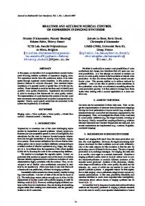
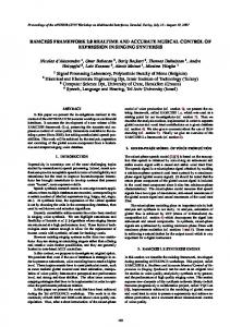
Figure 5: Two practical and real-time applications of the proposed 3D sensor. Top, 3D people tracking (RGBD sensor configured at 640 × 480 resolution). Bottom, a wearable mobility aid for the visually impaired (RGBD sensor configured at 320 × 240 resolution). two embedded applications that rely on the proposed RGBD sensor for depth sensing. At the top of the figure, results regarding a 3D people tracking system and, at the bottom, results concerned with a wearable mobility aid for the visually impaired that detects and categorizes obstacles by processing the 3D data provided by our RGBD sensor. The results reported in the figure include the filtering module that effectively removes most outliers and occlusions. Figure 6 reports, for the proposed stereo matching module only, the implementation results on three different Spartan 6 models (45, 75 and 100) for a constant disparity range of 32. Focusing the attention on the 75 model, we can notice that the stereo matching module requires 38 % BRAMs, 9 % Flip-Flops and 50 % of LUTs leaving a significant amount of resources for the other, and less demanding modules, included in the processing pipeline. In this specific implementation, as already pointed-out, our processing pipeline is clocked at the same frequency of the incoming pixels. Our RGBD sensor, processing at 30+ Hz stereo pairs with a disparity range of 32 at VGA resolution has an overall power requirement (provided by the USB cable) below 2.5 W. When used wit an embedded CPU board such as the Odroid U3, the overall power consumption is about 5 W, comparable to the solution proposed in [10]. The overall weight of RGBD sensor with M12 lenses and holders is about 90 g and hence suited for application domains, such as those involving UAVs/drones and wearable devices, where weight, size and power consumption are major concerns.
Figure 4: Raw disparity maps computed on a stereo pair of the Kitti dataset (Top) and on a stereo pair acquired with our stereo-head (Bottom).
we can notice that the RMSE is always below 0.3 pixel even in the worst case (sub-sampling factor 32 and 1 bit for fixedpoint arithmetic computations). With a reasonable trade-off between accuracy and memory/resource, sub-sampling factor 16 and 4 bit for fixed-point, the RMSE drops below 0.04 pixel. Hence, and as also confirmed by our evaluation in different application scenarios, the simplified strategy does not perturb significantly disparity map computation. Moreover, it makes manageable the undistortion parameters within the FPGA. In fact, compared to the standard approach based on full undistortion tables, in our setup, the amount of elements is reduced by a factor S = 162 that, considering images at VGA resolution (640), means that the amount of required elements drops from 307200 to 1200. This latter values is fully compatible with the internal memory resources of most FPGAs and certainly with our target Spartan 6 devices. Table 2 compares the raw results of the proposed hardwarefriendly version of the SGM algorithm with [14] and [18], according to the metric defined in [14], on two images of the Middlebury dataset [12]. We can notice a significantly lower average error with respect to [14] and [18]. In figures 4 we report, at the top, the raw disparity maps computed with a stereo pair of the KITTI [6] dataset and, at the bottom, with a stereo pair acquired with our camera. Observing these maps, we can notice that, in both cases, the proposed approach allows to infer quite accurately the 3D structure of the sensed scene. The results reported in the figure do not include the filtering module that is particularly effective to remove outliers. In Figure 5, we report the output of
6.
CONCLUSIONS
In this paper we have described the architecture of a custom RGBD sensor based on passive stereo technology and its visual processing pipeline self-contained into a single and low-cost FPGA. Although the simplified hardware design proposed, compared to more complex solutions, has several advantages (costs, power consumption, weight and size) the implementation of a processing pipeline for accurate dense depth measurements required a significant effort aimed at determining the best trade-off between accuracy and logic resources. The results of this work is a compact, lightweight and accurate RGBD sensor capable of processing stereo pairs at 30+ Hz at VGA resolution and with small energy requirements compatible with the constrained power supply pro-
Table 2: Average errors, computed according to [14] on non-occluded points, for Teddy and Cones [12]. Ref. [14] Ref. [18] Proposed cones 29.2 17.1 2.74 teddy 26.8 21.5 2.90
150
Figure 6: Resources required by the proposed SGM module, with a fixed disparity range of 32, on three Xilinx Spartan 6 models (45, 75 and 100). vided by the USB 2 standard. Experimental results confirm the effectiveness of our proposal.
7.
[10] D. Honegger, H. Oleynikova, and M. Pollefeys. Real-time and low latency embedded computer vision hardware based on a combination of fpga and mobile cpu. In Intelligent Robots and Systems (IROS 2014), 2014 IEEE/RSJ International Conference on, pages 4930–4935, Sept 2014. [11] S. Mattoccia. Stereo vision algorithms for fpgas. In The 9th IEEE Embedded Vision Workshop, CVPR 2013 Workshop, 2013. [12] D. Scharstein and R. Szeliski. A taxonomy and evaluation of dense two-frame stereo correspondence algorithms. Int. Journal Computer Vision, 47(1/2/3):7–42, 2002. [13] K. Schmid and H. Hirschmuller. Stereo vision and imu based real-time ego-motion and depth image computation on a handheld device. In Robotics and Automation (ICRA), 2013 IEEE International Conference on, pages 4671–4678, May 2013. [14] F. Schumacher and T. Greiner. Extension and fpga architecture of the generalized hough transform for real-time stereo correspondence. In Design and Architectures for Signal and Image Processing (DASIP), 2013 Conference on, pages 223–229, Oct 2013. [15] Y. Shan, Y. Hao, W. Wang, Y. Wang, X. Chen, H. Yang, and W. Luk. Hardware acceleration for an accurate stereo vision system using mini-census adaptive support region. ACM Trans. Embed. Comput. Syst., 13(4s):132:1–132:24, apr 2014. [16] F. Stein. Efficient Computation of Optical Flow Using the Census Transform. In Proceedings of the 26th DAGM Symposium, pages 79–86, 2004. [17] B. Tippetts, D. Lee, K. Lillywhite, and J. Archibald. Review of stereo vision algorithms and their suitability for resource-limited systems. Journal of Real-Time Image Processing, 2013. [18] C. Ttofis and T. Theocharides. Towards accurate hardware stereo correspondence: A real-time fpga implementation of a segmentation-based adaptive support weight algorithm. In Design, Automation Test in Europe Conference Exhibition (DATE), 2012, pages 703–708, March 2012. [19] R. Zabih and J. Woodfill. Non-parametric local transforms for computing visual correspondence. In Proceedings of the Third European Conference-Volume II on Computer Vision - Volume II, ECCV ’94, pages 151–158, 1994.
ACKNOWLEDGMENTS
The authors would like to thank Marco Casadio, Ilario Marchio and Vincenzo Villani for their contribution to this project.
8.
REFERENCES
[1] C. Banz, H. Blume, and P. Pirsch. Real-time semi-global matching disparity estimation on the gpu. In Computer Vision Workshops (ICCV Workshops), 2011 IEEE International Conference on, pages 514–521, Nov 2011. [2] C. Banz, S. Hesselbarth, H. Flatt, H. Blume, and P. Pirsch. Real-time stereo vision system using semi-global matching disparity estimation: Architecture and fpga-implementation. In ICSAMOS, pages 93–101, 2010. [3] L. di Stefano, M. Marchionni, and S. Mattoccia. A fast area-based stereo matching algorithm. Image Vision Comput., 22(12):983–1005, 2004. [4] S. Gehrig and C. Rabe. Real-time semi-global matching on the cpu. In Computer Vision and Pattern Recognition Workshops (CVPRW), 2010 IEEE Computer Society Conference on, pages 85–92, June 2010. [5] S. K. Gehrig, F. Eberli, and T. Meyer. A real-time low-power stereo vision engine using semi-global matching. In ICVS, pages 134–143, 2009. [6] A. Geiger, P. Lenz, and R. Urtasun. Are we ready for autonomous driving? the kitti vision benchmark suite. In Conference on Computer Vision and Pattern Recognition (CVPR), 2012. [7] K. T. Gribbon, C. T. Johnston, and D. G. Bailey. A real-time fpga implementation of a barrel distortion correction algorithm with bilinear interpolation. In In Proceedings of the Image and Vision Computing New Zealand, pages 408–413, 2003. [8] H. Hirschm¨ uller. Stereo processing by semiglobal matching and mutual information. IEEE Trans. Pattern Anal. Mach. Intell., 30(2):328–341, 2008. [9] H. Hirschm¨ uller and D. Scharstein. Evaluation of stereo matching costs on images with radiometric differences. IEEE Trans. Pattern Anal. Mach. Intell., 31(9):1582–1599, 2009.
151