Jordi Domingo-Pascual, Josep Solé-Pareta, Juanjo López-Mellado. Departament d'Arquitectura de Computadors, Universitat Politècnica de Catalunya. C/ Jordi ...
A Path Establishment Approach in an MPLS-ATM Integrated Environement Sergio Sánchez-López, Xavier Masip-Bruin, Jordi Domingo-Pascual, Josep Solé-Pareta, Juanjo López-Mellado Departament d’Arquitectura de Computadors, Universitat Politècnica de Catalunya C/ Jordi Girona, 1-3-08034 Barcelona, Spain Abstract-Multiprotocol Label Switching (MPLS) is an advanced forwarding scheme, which allows the network to achieve the Traffic Engineering (TE) objectives. When two or more MPLS nodes are connected via an ATM backbone merely composed of ATM switches, it is necessary to add some mechanisms to allow the label distribution and allocation between both nodes. In this paper a solution is proposed to integrate ATM and MPLS, so that the ATM backbone will be seen as a unique MPLS node from the MPLS domain and as a consequence of that the end-to-end LSP establishment can be carried out.
I.
INTRODUCTION
The current Internet growth and progressive request of specific services such as videoconferences and, in general, real time communications, have resulted in the creation of several mechanisms that manage to guarantee certain Quality of Service (QoS). One of these methods, proposed by the IETF, to solve the QoS problem is Traffic Engineering (TE) [1], a mechanism used to achieve both optimization of the network performance and resources utilization. One useful tool for TE is the Multiprotocol Label Switching (MPLS) [2]. MPLS is an advanced forwarding scheme based on the allocation of a short fixed length label to every packet. An MPLS domain ingress node attaches labels to packets according to the concept of Forwarding Equivalence Classes (FEC) [2]. Before forwarding a data flow, an explicit Label Switched Path (LSP) must be set up. In order to achieve this, MPLS uses a Label Distribution Protocol (LDP) [2] that will perform the label distribution between all the path nodes. A problem exists when two or more domains are connected via a non-MPLS cloud, for instance when an ATM backbone interconnects two MPLS domains. In this case, the end-toend LSP establishment is not possible, unless some mechanism is added to the network [3]. A similar problem appears when IP traffic has to cross an ATM zone. A solution is presented in [4] where the Private Network-Network Interface (PNNI) and PNNI Augmented Routing (PAR) are proposed to This work was supported by the Spanish Research Council (CICYT) TEL99-1117-C03-3 (SABA2) and the Catalan Research Council (CIRIT) 1999-SGR00126.
integrate IP and ATM. PNNI [5] is a standard routing protocol used by ATM switches, defined by The ATM Forum. PAR, which is an extension of PNNI, is a result of common work between the ATM Forum and IETF [6], [7]. Moreover, an optional set of protocols, named Proxy-PAR, has been defined to allow a non PAR-capable client to interact with a PAR-capable server and thus obtain the PAR capabilities. The server acts as a proxy for the client in the PAR operation. The client is able to register its own services, and query the server to obtain information on compatible services available in the ATM network. In this way, non-ATM information can be transported through an ATM cloud to all the nodes connected to other networks. Starting from this idea, in this paper we suggest a solution to integrate ATM and MPLS, so that the ATM backbone will be seen as an only MPLS node from the MPLS domain and as a consequence of that the end-to-end LSP establishment can be carried out. The remainder of this document is organized as follows: in Section 2 we analyze a suggestion proposed in [8] to distribute labels throughout the ATM cloud and set up an LSP in certain situations. In Section 3, we suggest a solution for setting up an end-to-end LSP in any given situation. In Section 4 we view an example where our suggestions are implemented. Section 5 shows the results obtained from the simulations carried out. Finally, in Section 6, we present the conclusions. II.
MPLS AND ATM
In order to forward MPLS traffic, we need to set up an LSP from a source node to a destination node. A Label Distribution Protocol is used to distribute the labels. Existing protocols such as Resource Reservation Protocol (RSVP) [9] or a new set of specific procedures called LDP [10] could be used by Label Switching Routers (LSR) to distribute labels. All the nodes along the path must be LDP capable. Therefore, when an ATM backbone merely composed of ATM switches and SVC ATM is between two MPLS domains, these switches are non-LDP capable. A solution is suggested in [8] where the capability of the PNNI to transport topology information
is used to distribute labels. An architecture for the ATM border routers (BR) is proposed and it is composed of an LSR performing both the routing functions of the network layer and the typical MPLS functions. A proxy PAR client is added to register and obtain information about the Proxy PAR server. Moreover, it has an ATM switch utilizing the PAR protocol, with the Proxy PAR server installed. Finally, a forwarding table setting up the relationship between MPLS labels and ATM outgoing interfaces is added. PNNI Topology State Packet (PTSP) is used by the PNNI to transport information through the network. Each one has several PNNI Topology State Elements (PTSEs) with a set of Information Groups (IG). To be able to transport MPLS information we proposed a new specific IG [8]: PAR MPLS Services Definition IG essentially contains the IP address reachable from itself and a label that is allocated to this address. Once the information is registered in all the BRs, PNNI floods it throughout the network. Each BR creates a table with both MPLS and ATM information received. When an LDP is started in an MPLS domain to set up an LSP, an LDP message crosses the nodes to find a label for the current FEC. In our case, LDP will reach a BR of the ATM backbone with MPLS topology information, which will have a relation between labels and FECs (the reachable IP addresses by the rest of the BRs will be used as an FEC). LDP will find a label for the destination IP address where the data flow will be sent, and the LDP message will return to the source node setting up the relation in each of the path nodes. Simultaneously, the BR will set up a Virtual Circuit (VC) towards the destination BR in the ATM cloud. In this way, the end-to-end LSP will be established. III.
LSP ESTABLISHMENT
This solution allows terminals, LANs and Autonomous Systems, to be connected using MPLS as fast forwarding scheme, through an ATM backbone. Terminals and LANs could be considered as end systems, where the BR that connects them to the ATM backbone is the last router of the path, therefore an LSP could be set up end to end. The problem exists when the egress BR is connected to an MPLS domain where there are several nodes before the destination node. In this case, the LSP could not be set up end to end because the egress BR does not send a message to set it up. A solution will be to develop a mechanism to allow an LDP message to be sent from egress BR to MPLS destination node. We suggest a method to solve this problem as follows. The RSVP-TE [9] is used as LDP to distribute the labels along the path. When a Path message arrives at the ingress
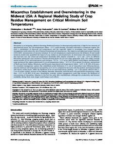
BR, a Resv message is returned to the source node with the label corresponding to the destination IP address. Immediately, a VC is set up by the PNNI from ATM switch of ingress BR to ATM switch of egress BR. The PNNI signaling is based on a UNI 4.0 signaling subset and some features about the use of PNNI routing to set up dynamic call are added. RSVP, as set up protocol, starts a call set up in the ingress BR to establish a VC towards the egress BR. A SETUP message is used to set up the connection and could contain some Generic Identifier Information Element [11] that will be transported through the ATM network as opaque information, except if they contain coding rule error. In this paper we suggest adding a new Generic Identifier Information Element in the SETUP message with an Identifier related standard/application field of value (0x06) corresponding to MPLS, and an identifier type of value (0x02) corresponding to Resource. In this case the Identifier is the MPLS VCID used in [12] to solve the problem of using the VPI/VCI field as MPLS label in SVC ATM networks. This identifier is used to identify an ATM VC in an LDP mapping message and is transported end to end between ATM LSR to achieve the same value at both ends. However, in our case the labels have been allocated and sent between all the BRs. Therefore, transporting a VCID will not be needed. We suggest replacing the VCID with the IP address of the MPLS destination node, as we can see in Fig.1. When the message SETUP with the Generic Identifier is received, the egress BR obtains information about the protocol that will be used in the connection (MPLS), the identifier type (Resource) and the destination IP address. Therefore, the egress BR has enough information to set up an LSP, sending the RSVP Path message towards the MPLS node with an IP address equal to the IP address that is contained in the Identifier. Note that we try to set up simultaneously an end-to-end LSP bearing in mind that there is an ATM backbone between two MPLS domains. Therefore, when the Path message arrives at the ingress BR and obtains the label, a Resv message is returned to the source node. At the same time, a SETUP Information Element Identifier= Generic identifier transportIE (0x7F) Coding standard IE instruction field
Ext
Length of contents of information element
1 2 3-4
Identifier related standard/aplication = MPLS (0x06)
5
Identifier type=Resource(0x02)
6
Identifier length=4 octets(0x04)
7
@IP MPLS node destination (4 octets)
Fig. 1. Generic Identifier
11
message is sent from ingress BR to the egress BR. When this message has arrived at its destination, a CONNECT message is returned to the egress BR to complete the VC establishment. At the same time, the egress BR analyzes the Generic Identifier Element Information and starts the corresponding process to set up the last part of the total LSP. IV.
SCENARIO
Now, we are going to analyze the proposals made in this paper with one example. Before analyzing the example, a set of considerations should be imposed in order to define the scenario where the experiences will be carried out. The scenario is shown in Fig. 2. Firstly, we consider two IP/MPLS networks (named Network Domain 1, ND1, and Network Domain 3, ND3) interconnected through an ATM backbone (named Network Domain 2, ND2). This backbone is made of ATM switches and BRs, which allow other networks and hosts to be connected to the backbone. The PAR protocol extended with the previously proposed modifications is used in the ATM network. In order to reduce the model complexity only one hierarchy level is assumed. Both, the signaling and the topology distribution are implemented by the PNNI protocol. Secondly, we assume that all the IP/MPLS nodes are LSRs and the RSVP-TE is used as an LDP. So, the LSP setup will be performed by the Ordered LSP Control. Because of the implemented functions in the BRs both IP/MPLS networks will act as if the BRs were an end node. As a consequence, after a Path message with a label request object has been sent along the path, the ingress BR returns a Resv message to the source MPLS node as if it were the end node along the path. Moreover, the egress BR triggers a Path message to the destination MPLS node, as if it were the source node.
1) The Proxy PAR client on each BR registers the MPLS protocol along with labels, and all the address prefixes which can be reached. Every server bundles its state information in PTSEs, which are encapsulated within a PTSP, which is sent to a neighboring peer. Using the received PAR MPLS devices Definition IG, every server side generates an MPLS topology database as shown in Fig. 3. Each client side will use the query protocol to obtain information about registered services by other clients. 2) Node LSR1 in ND1, decides to send traffic to LSR8 (IP@=147.84.2.3), which is situated in ND3. Therefore, an LSP between LSR1 and LSR8 should be set up, and every node along the path should have the relation established. Then, a RSVP Path message in LSR1 (with the IP destination address) is triggered in order to request a label. At the moment that this message reaches BR1 it receives the label 0.40 which is bound to the indicated destination address. 3) BR1 returns a Resv message to LSR1. Simultaneously, BR1 triggers the VC establishment mechanism to the BR3 ATM address given by the table in Fig.3. To perform this, a SETUP message containing the Generic @IP Dest
@ATM
Label
BR1
@IP Dest
@ATM
Label
BR3 147.82.2.1
@BR2
0.50
147.82.2.1
@BR2
0.50
147.84.0.0
@BR3
0.40
147.81.0.0
@BR1
0.20
147.83.2.0
@BR4
0.30
147.83.0.0
@BR4
0.30
@IP Dest
@ATM
Label
@IP Dest
@ATM
Label
BR2
BR4 147.81.0.0
@BR1
0.20
147.82.2.1
@BR2
0.50
147.84.0.0
@BR3
0.40
147.84.0.0
@BR3
0.40
147.83.2.0
@BR4
0.30
147.81.0.0
@BR1
0.20
The mechanism used to set up the LSP is: Fig. 3. BRs topology database Network domain 1
Network domain 2 BR2
Network domain 3
147.82.2.1 LSR6
¸
·
Path
LSR1
LSR7
LSR2
SETUP
LSR3
¹
Path
CONNECT LSR4 147.81.0.0
Resv
¸
LSR5
¹
BR1
Resv
147.84.2.3
º BR3
LSR8
147.84.0.0
LSR
147.83.2.0 BR4
ATM Switch BR
Fig.2. Network topology scenario
Identifier Information Element suggested in this paper with the LSR8 IP address is sent. 4) When the SETUP message reaches BR3, a CONNECT message is sent to BR1 in order to perform the VC establishment. Simultaneously, BR3 sends a Path message to the received IP destination address, i.e. to LSR8, in order to set up the LSP in ND3. 5) A Resv message to BR3 is returned by LSR8, establishing the set of label bindings, which will create the LSP. Once this process has finished the network can be modeled according to the topology shown in Fig.4. As we can see, at the moment that the path is set up, the ND2 behavior is as if it was a unique LSR, called Virtual LSR (LSRV). This node is the last node along the path in ND1, while in ND3 it is responsible of setting up the path towards a destination node LSR8, carrying out the source node functions. V.
NUMERICAL RESULTS
In this section, the effectiveness of our proposal is demonstrated by comparing it with other LSP establishment mechanisms. Firstly, in order to compute the time needed by the LSP establishment, a mathematical model of our proposal is presented. This model has been calculated under certain specific working conditions. The following notation will be used: TLSP: total time needed to establish the end-to-end LSP, N1: number of nodes along the path in ND1, N2: number of switches crossed by the MPLS traffic in ND2, N3: number of nodes along the path in ND3, BW1: link bandwidth in MPLS1 domain, BW2: VCC bandwidth in ATM domain, BW3: link bandwidth in MPLS3 domain, BWL: link bandwidth in ATM domain, tR: delay in LSR, , tS: delay in switch, SPACK: IP packet size, SC: ATM cell size, SPATH: Path message size, SRESV: Resv message size, tPACK: time needed by a IP packet in order to reach the egress BR from the source node, tPATH1: time needed by a Path message in order to reach the ingress BR, tRESV1: time needed by a Resv message in order to reach the source node from the ingress BR, tSET: time needed by a SETUP message in orLSR1
LSR2
LSR3
LSR4
LSRV
der to reach the egress BR from the ingress BR, tCON: time needed by a CONNECT message in order to reach the ingress BR from the egress BR, tPATH3: time needed by a Path message in order to reach the destination node from the egress BR, tRESV3: time needed by a Resv message in order to reach the egress BR from the destination node. According to the notation shown above, the time needed to setup an LSP between two MPLS nodes situated in two different domains connected through an ATM backbone, is represented by TLSP = t PATH1
+ max[t RESV1 , tSET + max(t PATH3 + t RESV3 , t CON )].
(1)
Equation (1) depends on the number of nodes existing on each domain along the path. In order to simplify the expressions the following considerations have been taken into account: equal delay time in all the LSRs existing in the MPLS domains, equal ATM signaling message size for all the ATM messages and there are only two messages in the VC setup. Applying this we have that
S TLSP = PATH + t R N1 BW1 SRESV + t R N1 , BW1 SPATH SRESV + t R N3 + + max + t R N3 . BW3 BW3 SC + + BW t S N2 max S , C + t S N2 L BWL (2) In order to compare with other LSP establishment mechanisms, we can analyze the behavior of different topologies under both these different mechanisms and the mechanism suggested in this paper. In order to perform this, it is necessary to bear in mind that different cases are possible: 1.
The ATM network is made of ATM LSRs. In this case we can consider that all the nodes are MPLS capable nodes and the RSVP is used as LDP. We will simulate LSR5
LSR6
LSR7
ATM
Fig. 4. Network topology with the ATM backbone as an MPLS node
LSR8
its behavior as if the network would have three MPLS domains. Equation (2) is S S TLSP = t PATH + t RESV = PATH + t R N 1 + PATH + t S N 2 BW BW 1 2 S S S + PATH + t R N 3 + RESV + t R N 1 + RESV + t S N 2 BW1 BW1 BW2 S + RESV + t R N 3 . BW3
TLSP = t PATH1 + t TUNNEL − PATH 2 + t PATH 3 + t RESV 3 S S + t TUNNEL − RESV 2 + t RESV1 = PATH + t R N1 + PATH BW BW2 1 S S S + PATH + t R N 3 + RESV + t R N 3 + RESV BW2 BW3 BW3
(4)
As we know the path is simultaneously established in ND1, ND2 and ND3. Because of this the source node could send traffic before the LSP setup process in the ATM backbone or in the ND3 had been finished. In order to test the effects produced by this bug, an analysis has been performed. The different cases are: 1. The LSP is completely established when the source node starts sending traffic. The condition is determined by the tRESV1 according to t RESV1 ≥ t SET + max (t PATH 3 + t RESV 3 , t CON ).
(5)
2. And if the expression is t RESV1 < t SET + max (t PATH 3 + t RESV3 , t CON ).
(6)
Two possible cases appear, always considering that the backbone ATM VC is established: i. The first case can be represented by t RESV1 + t PACK ≥ t PATH 3 + t RESV3 .
(7)
In this case, as in the first case, the path is completely established before the traffic flows along the path ii. The second case can be represented by t RESV1 + t PACK < t PATH 3 + t RESV3 .
t PACK = t PATH 3 + t RESV 3 − t RESV1.
(3)
2. The ATM network does not implement the PNNI in such a way that the BRs do not have topology information about the other BRs. One method to set up the LSP is proposed in [12]. In this case (2) is
S + RESV + t R N1 . BW 1
In this case, depending on the first packet size of the MPLS traffic, it is possible that the path setup in the ND3 is still in progress when the first packet flows from the source node to the ingress BR. The condition that the first packet size must fulfill so that when this packet reaches the ingress BR the end-to-end LSP will be completely established is
(8)
According to (9), the first packet size in order to have the end-to-end LSP completely established is S PACK =
BW1 BW2 N 1 BW2 + BW1
S S + S RESV x PATH + 2t R N 3 − RESV + 2t R N 1 − t S N 2 . BW3 BW 1
(10) Once the analytical expressions have been obtained, we are going to compute the numerical results to compare the different methods explained above. In order to perform the graphic representation, the following values will be constants: BW1=BW2=2Mbps, BWL=155Mbps, tR=71µs, tS=10µs, SC=53bytes, SPATH=112bytes and SRESV=120bytes. The rest of the parameters will be modified to obtain a meaningful set of results from the suggested method. From the above equations, we have computed how many times faster our proposal is compared to the mechanism proposed in [12] in setting up the end-to-end LSP, which we call speed-up. From (2) and (3), we obtained the curves of Fig. 5, and from (2) and (4) we obtain the curves shown in Fig. 6. In both cases for BW2=34Mbps. Moreover, in order to reduce the complexity, in the second case we consider that the VC between BR1 and BR3 is already set up. Fig. 5 and Fig. 6 show that the speed-up grows (is better) when increasing N3 up to a maximum, which is where N1 is the double of N3. From here on, when N3 increases its value, the speed-up decreases until reaching a permanent value over 1. This shows that our solution is better than the method proposed in [12]. Finally we have computed the IP packet size in order to fulfill the condition in (7). From (10) with BW2=34Mbps we obtained the curves shown in Fig. 7 and from (10) with BW2=2Mbps we obtained the Fig. 8. Fig. 7 and Fig. 8 show that the worst case is produced when BW2 is 34Mbps and N1 is 7 times higher than N3 considering an IP packet size over 1500 bytes. For IP packets shorter than 1500 bytes, IP packets could arrive to the egress BR before the LSP was set up, in that case the egress BR will place the packets in a queue until the Resv message from destination node would be received.
1.6
2100
N1=20 N1=10 N1=2
2000 N2=7 N1=20
1900
N2=7 N1=10 N2=7 N1=2
1800
1.5
1700
N2=20 N1=20 N2=20 N1=10
1600
N2=20 N1=2
1500
1.4
1400
1200 bytes
Speed-up
1300
1.3
1100 1000 900 800
1.2
700 600 500 400
1.1
300 200 100
1
0
2
3
4
5
6
7
8
9
10
11
12
13
14
15
16
17
18
19
20
1
2
3
4
5
6
7
8
Fig. 5. Speed-up LSR
11
12
13
14
15
16
17
18
19
20
19
20
600
N1=20 N1=10 N1=2 1.5
500
1.4
400
bytes
Speed-up
10
Fig. 7. Packet size for BW2 = 34Mbps
1.6
1.3
N2=7 N1=20 N2=7 N1=10 N2=7 N1=2 N2=20 N1=20 N2=20 N1=10 N2=20 N1=2
300
1.2
200
1.1
100
0
1 2
3
4
5
6
7
8
9
10
11
12
13
14
15
16
17
18
19
20
1
Number of nodes in N3
CONCLUSIONS
In this paper a solution for connecting two MPLS networks through an ATM backbone which implements the PNNI and the Proxy PAR is presented. As we have seen in Section 5, at this moment some different options exist in order to address the same problem. The main advantage of our proposal with regard to some of these other contributions is that unlike these, the addition of an LSR over each ATM switch or the encapsulation and transport of a signaling protocol through an ATM cloud is avoided. Moreover, as a consequence of the comparison performed between our mechanism and two other mechanisms, we can say that our proposal needs less time to establish the end-to-end LSP. So, our mechanism allows the network to reduce its setup time, improving its throughput.
[3] [4] [5] [6] [7] [8]
[9] [10] [11]
REFERENCES D.O. Awduche, J. Malcolm, J. Agogbua, M. O’Dell and J. McManus, “Requirements for Traffic Engineering over MPLS”, IETF RFC 2702, June 1999.
3
4
5
6
7
8
9
10
11
12
13
14
15
16
17
18
Fig. 8. Packet size for BW2 = 2Mbps [2]
VI.
2
Number of nodes in N3
Fig. 6. Speed-up RSVP TUNNEL
[1]
9
Number of nodes in N3
Number of nodes in N3
[12]
E.C. Rosen, A. Viswanathan and R. Callon, “Multiprotocol Label Switching Architecture”, IETF RFC 3031, July 2000. B. Davie et al., “MPLS using LDP and ATM VC Switching”, IETF RFC 3035, Jan. 2001 R. Haas, P. Droz and D. Bauer, “PNNI Augmented Routing (PAR) and Proxy-PAR”, Computer Networks, vol. 34 (2000), pp. 399-418. ATM Forum “Private Network-Network Interface Specification Version 1.0”, af-pnni-0055.000, March 1996. P. Droz and T. Przygienda, “Proxy-PAR”, IETF RFC 2843, May 2000. T. Przygienda, P. Droz and R. Haas, “OSPF over ATM and ProxyPAR”, IETF RFC 2844, May 2000. S. Sánchez-López, X. Masip-Bruin, J. Domingo-Pascual, J. SoléPareta, “A Solution for Integrating MPLS over ATM”, in Proc 15th International Symposium on Computer and Information Sciences (ISCIS2000), Oct. 2000, pp.255-303. D.O.Awduche et al. “RSVP-TE: Extensions to RSVP for LSP Tunnels”, draft-ietf-mpls-rsvp-lsp-tunnel-08.txt, Feb. 2001. L. Andersson, P. Doolan, N. Feldman, A. Fredette and B. Thomas, “LDP Specification”, IETF RFC 3036, Jan. 2001. M. Suzuki, “The Assignment of the Information Field and Protocol Identifier in the Q.2941 Generic Identifier and Q.2957 User-to-user Signaling for the Internet Protocol”, IETF RFC 3033, Jan.2001. K. Nagami, Y.Katsube, N. Demizu, H. Esaki and P. Doolan, “VCID Notification over ATM link for LDP”, IETF RFC 3038, Jan.2001.