Establishment processes, taking the former out of the routing hardware, while ..... After this first testing stage, further refinement of the software components.
A PCE-based Connectivity Provisioning Management Framework E. Grampín, A. Castro, M. Germán, F. Rodríguez, G. Tejera, M. Sanguinetti Instituto de Computación, Universidad de la República, Montevideo, Uruguay E-mail: {grampin, acastro, mgerman, rodrigue, gtejera, msangui}@fing.edu.uy Abstract—Many carriers and Service Providers (SPs) use MPLS to achieve Traffic Engineering (TE) objectives, such as network resources optimization, support for end-to-end QoS guarantees services, aggregated traffic measurement and fast recovery against link/node/Shared Risk Link Group (SRLG) failures. The three main Traffic Engineering components of MPLS are the routing component, responsible for the discovery of the network topology, the path computation component, responsible for the assignment of resources to traffic demands, and the signaling component, responsible for the establishment of the Label Switched Paths (LSPs) along the computed path. Path Computation under QoS and administrative constraints is usually performed sub-optimally in network nodes, which are mainly dedicated to traffic forwarding. Off-load of this task to specialized network entities is a key aspect of the Path Computation Element (PCE) Architecture. This paper describes an ongoing implementation of such architecture seeking for cooperation of Control and Management Plane components for overall network Operation and Management optimization. Early functional testing of the software components, performed in cooperation with a Service Provider, is presented. Index Terms—Connectivity Provisioning, Path Computation Element, Distributed systems
I. INTRODUCTION Connectivity Provisioning is a two phase process that performs allocation of network resources to traffic demands. These phases are Path Computation and Connection Establishment. The former is a complex process, which consists in the resolution of the Constraint-Based Routing (CBR) problem, a fundamental building block for traffic engineering systems such as Multiprotocol Label Switching (MPLS) and Generalized Multiprotocol Label Switching (GMPLS) networks (in the document we use the short expression (G)MPLS). Once a network path is found, the Connection Establishment process shall enforce the transport of a given traffic flow end to end through the network. (G)MPLS has developed a powerful Control Plane that permits the completion of both phases. Ingress Label Switch Routers (LSRs) perform on-line Path Computation for a given Forwarding Equivalence Class (FEC) (i.e. a traffic flow), usually using some heuristic capable of finding feasible network paths such as Constraint Shortest Path First (CSPF), and then proceed to the Connection Establishment phase using a signaling protocol such as RSVP-TE [1]. The overall process is undertaken in tens of millisecond. Path computation in large, multi-domain, multi-region, or multi-layer networks is complex and may require special computational components and cooperation between the
different network domains. The Path Computation Element (PCE) architecture has been proposed by the IETF [2], based on the idea of decoupling Path Computation from Path Establishment processes, taking the former out of the routing hardware, while keeping the latter under Control Plane responsibility. The PCE functionality is orthogonal to the forwarding capacity of the node in which it is implemented. Centralized, off-line route computation has been practised in transport networks since long ago. Given the network topology and a static traffic matrix, a route server can compute an optimal distribution of resources. In these type of networks, management procedures (either automatic and/or manual) translate the routing decisions to specific device configuration (i.e. SDH cross-connections). The overall process may take from hours to days to complete. This is not acceptable in (G)MPLS networks, where routing decisions must be taken on-line; the introduction of the PCE architecture permit ingress LSRs to demand constraint-based Path Computation to a route entity using a request/reply protocol, and once a request is obtained, proceed with normal signaling procedures in the Control Plane. This architecture has the fundamental advantage of keeping complex CBR computation out of the routers, while maintaining the network setup times in the tens of milliseconds timescale. The basic assumption is that the overhead introduced by the request/reply communication protocol and computation time in the PCE is negligible. Other advantages, described in next chapter, include load sharing options, objective function choice, and inter-layer optimization, among others. Nevertheless, there are important aspects that have not been completely addressed by the PCE architecture, notably the integration with the Service Provider management framework, which usually comprise several Element Managers (EM), Network and Service management applications. The Routing and Management Agent (RMA) architecture introduced by [3] integrate the PCE relevant aspects into a synergistic solution, which uses both the Control and Management Plane for dynamic Connectivity Provisioning in (G)MPLS networks. This architecture may be integrated into a practical operational Traffic Engineering (TE) strategy for Service Providers. In this paper we review an ongoing implementation of the compound RMA/PCE architecture under a real world Operation & Management scenario. The paper is structured as follows: Section II describes the proposed architecture, Section III is dedicated to the implementation aspects, while early results are discussed in Section IV. Finally, some
concluding remarks are presented in Section V. II. RMA/PCE A RCHITECTURE This architecture evolves from the GERMINA proposal presented in [4], and follows the same component-based software development approach. The following sub-section reviews relevant aspects of the PCE architecture, and later we discuss the RMA/PCE compound proposal. A. Description of the PCE architecture In this architecture path computation does not occur on the head-end (ingress) LSR, but on some other path computation entity that may physically not be located on the head-end LSR. The initial motivation for this architecture is to off-load CPUintensive path computation with multiple constraints from routers; additional advantages can be obtained from the existence of traffic engineering database repositories, which may be used for path computation in cases with partial topology visibility or absence of a TED (for example, because a non-TE-enabled IGP is used in the network). Backup path computation is another drive for the PCE architecture, and also networks elements that lack Control Plane or routing capabilities, such as “headless” Optical Cross-Connects (OXCs), may benefit form the architecture. In this case, the GMPLS Control Plane intelligence is off-loaded to a colocated entity, the Connection Controller, defined in [5], which may also include the PCE capability. The main components of the PCE architecture are the following: •
•
•
•
•
TE LSP: Traffic Engineering MPLS Label Switched Path. This is a unidirectional connectivity object which route (either explicit or loose) is computed under QoS and administrative constraints. PCE: Path Computation Element. An entity (component, application, or network node) that is capable of computing a network path or route based on a network graph and applying computational constraints. PCC: Path Computation Client. Any client application requesting a path computation to be performed by the Path Computation Element. TED: Traffic Engineering Database, which contains the topology and resource information of the domain. The TED may be updated by Interior Gateway Protocol (IGP) extensions or potentially by other means (e.g. by a management application). PCEP: Path Computation Element communication Protocol, for request/reply messages exchange between PCCs and PCEs, and between cooperating PCEs. This protocol, defined in [6], is capable of representing requests for path computation including a full set of constraints, and return multiple paths (for load balancing and/or protection purposes) using different objective functions. PCEP include security mechanisms such as authentication and confidentiality.
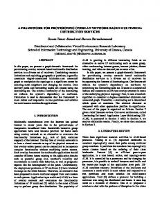
The inter-area (single IGP domain) scenario is being addressed by the PCE Working Group, while some work in the inter-area and inter-AS scenarios is being undertaken. The functional specification of (G)MPLS Traffic Engineered LSP path computation models involving PCEs includes the generation of primary, protection and recovery paths, as well as computations for (local/global) reoptimization and load balancing. Requirements for extensions to existing routing and signaling protocols in support of PCE discovery and signaling are also being considered [7][8]. The PCE is an entity that may or may not reside in a network router. The corresponding application models are called “Composite PCE Node” and “External PCE” respectively. Figure 1 shows the latter case, where the main architecture components are presented.
Figure 1 - PCE Architecture components – External PCE case
Other PCE application models are the “Multiple PCE Path Computation”, where intermediate nodes in an LSP path with loose hops may request additional path computation to extra, non-coordinated PCEs, and the “Multiple PCE Path Computation with Inter-PCE Communication”, where many PCEs may cooperate to compute a piece-wise network path, replying one coordinated result to the head-end node. Note that this model does not provide a distributed computation algorithm, but it allows distinct PCEs to be responsible for computation of parts (segments) of the path. Also note that the different models are indistinguishable from the PCC point of view, which just sends a path request and receives a reply from a single PCE, either strict or loose, without knowledge of PCE coordination. Therefore, single and/or multiple PCE Path Computation may be used, under a centralized or distributed computation model; for example paths that span multiple domains may be computed using the distributed model with one or more PCEs responsible for each domain, or the centralized model by defining a domain that encompasses all the other domains. The PCE WG is evolving towards the specification of a comprehensive path computation architecture, including the definition of metrics to evaluate path quality, scalability, responsiveness and robustness of path computation models.
B. Description of the RMA architecture As mentioned before, the RMA proposal addresses the integration of the PCE architecture relevant aspects in a synergistic solution, which uses both the Control and Management Plane for dynamic Connectivity Provisioning in (G)MPLS networks. In [2], the PCE architecture briefly states a Management-Based PCE Usage scenario, depicted in Figure 2:
• •
Extend PCEP in order to support the extra information (FEC, EM, possibly other). Keep PCEP “as is” and provide the extra information by other means.
The first option may be supported using the PCEP “reserved” fields, and implies to promote standardization in the IETF. We're working towards that direction in the prototype implementation, in order to demonstrate it feasibility. Nevertheless, we also support the second option, introducing a Management Interface front-end for the NMS and the RMA, which decide the appropriate module that satisfies the service required by external applications. The offered services to upper layer applications are generic connectivity provisioning, path computation, and TED access, among other possibilities. The modified architecture, which is a decomposition of the Management-Based PCE Usage scenario into implementation components is shown in Figure 3:
Figure 2 - Management-Based PCE Usage
This scenario introduces a provisioning request initiated by a Network Management System (NMS), using PCEP for path computation request, which employs a suitable mechanism for the “Service Request” configuration over the ingress LSR (head-end node). Precisely this “Service Request”, which shall specify endpoints, QoS attributes, FEC, among other parameters used as input for the path computation request, is a key aspect of Connectivity Provisioning left aside by the PCE architecture. The RMA implementation takes into account this and other aspects such as the relationship of path computation with Service, Network and Element Managers. In our implementation we intend to integrate the PCE functionality into a management framework, allowing external managers to access the TED information, for example to update the network inventory, introduce administrative policies (which will affect the CBR computation), or use the LSP setup capabilities. As shown in Figure 2, the PCE functionality shall be requested using the standard PCEP, but this option may not be enough for the intended integration. We propose to integrate the PCE into a more general provisioning architecture, the RMA, which can interact at the Management Plane with other applications, as previously mentioned. Therefore, a Management Interface is needed for the PCE component. An external application which intend to use the PCE for connectivity setup using this interface (i.e. delegates path computation and connection establishment to the PCE via PCEP), will find that there is no way of specifying a FEC, since PCEP does not include this information. Another drawback of this approach is that if the head-end node is not PCEP-enabled, is impossible to specify which EMS shall accomplish the configuration task, because this information is either included in the PCEP specification. Given the aforementioned limitations, two possible approaches may be taken:
Figure 3 - RMA/PCE Architecture
The following modules compose the NMS: •
•
Connectivity Provisioning: this module is the orchestrator for fulfillment of service requests received through the Management Interface. Network Inventory: this is the network objects repository, which in our case uses the MTNM Information Model [9], as specified in GERMINA. Note that a binding between the inventory and the Traffic Engineering Database is needed for management applications. Also note that the Inventory is fed by the Element Managers, e.g. by means
• • •
of notifications (as defined in MTNM). These relationships are represented as dotted arrows in the figure. PCC module, which implements the PCEP communication with the PCE and the EMS Selector. EMS Selector: proxy module for the vendor-specific Element Managers (EMS #x). Other components, such as Fault and Performance Management modules, are out of the scope of this article. The following modules compose the RMA:
•
•
•
•
PCE module, which implements the PCEP communication with the PCCs. Our implementation decouples the communication from the path computation functionality. CBR module: implementation of the path computation functionality. This module receives requests from the PCE and uses the information stored in the TED. Our prototype is implemented following [10]. TED module: as mentioned above, it contains the topology and resource information of the domain, augmented with administrative information (i.e. policies). Topology DB: IGP peering module, used to update network topology, but preventing traffic forwarding (note that the RMA/PCE functionality is orthogonal to the forwarding functionality).
The RMA/PCE components use the GRMA Protocol for internal communication. This request/reply communication protocol is described in next section. III. IMPLEMENTATION A SPECTS The system is implemented in Linux, kernel 2.6, using C/C++ and Java programming languages. Different distributed environments where considered for the implementation of the component-based architecture. On one side we had the option of implementing a tightly coupled system, using APIs or other language-dependent methodology; on the other side, industrystandard distributed environments such as CORBA and .NET may be used. The former approach has low communication overhead, but imposes heavy limitations for the introduction of new components; the latter is very flexible, but the communication overhead may be extremely high. As a trade-off we choose to implement a distributed environment founded over TCP transport of XML files; each component of the system listens to a system-known TCP port, using Berkeley sockets. The components implement the GRMA Protocol, which defines the messages exchanged, and transport the XML files with the needed information in the protocol payload. A. PCEP, PCC and PCE implementation PCC and PCE are the endpoints of the path computation request/reply process. Both entities are implemented using an object-oriented approach. The components run as Linux daemons, and create a new thread for each PCC-PCE session.
To exchange messages, the objects are serialized into a byte stream, which is transported using the PCEP definition [11]. As described in Section II.B, we found some missing objects in the PCEP while implementing the testing scenarios, such as FEC and EMS Selector information, among other possibilities. We're implementing such extensions in our own version of the protocol, following the WG progress in order to promote its standardization. B. EMS Selector and specific Element Managers These components implement the configuration management functionality for legacy, non-PCE compliant devices. The EMS Selector is a front-end for third-party Element Managers, which shall be integrated ad-hoc using the method provided by the router vendor. We currently support Cisco routers configuration, using IPEMSComm, a homebrewed Cisco EMS, implemented in Java following [12]. We plan to support Alcatel MPLS routers using the XML/JMS API provided by the 5620-Service Aware Manager [13]. C. TED design The RMA XML Schema Definition (XSD) is based on TOTEM toolbox Information Model [14] for the Traffic Engineering Database (TED). The persistence of the RMA objects is implemented using Hibernate [15], and the PostgreSQL relational database [16]. A number of optimizations are under progress to speed-up the response time of the CBR process. D. CBR module Finding a path that satisfies multiple additive/multiplicative constraints is known to be an NP-Hard problem. Furthermore, online path computation makes the problem worst, since future requests are not known. Several heuristics and exact algorithms have been presented to solve the problem of multiconstrained paths (MCP) and multi-constrained optimal paths (MCOP) in polynomial time (see [17]). The implementation also considers the computation of backup and/or load-sharing paths, using modified versions of the Dynamic Online Routing Algorithm for MPLS Traffic Engineering (DORA) [18] and the Self-Adaptive Multiple Constraints Routing Algorithm (SAMCRA) [19]. We took a simple approach to job parallelization of the CBR module, achieved by the execution of multiple instances in parallel, satisfying multiple requests at a given time. The access to the TED is optimized in the following way: the TED interface issues notifications when changes occur, and the CBR component can save time retrieving just the difference between topology queries. E. Topology DB update This module gathers network topology updates using the OSPF-API provided by the Quagga routing suite [20]. External applications (such as our topology DB update component) may catch up network updates and query the OSPF Topology DB. Additionally, SNMP usage is planned for retrieving extra monitoring information. Note that the RMA receives the Link State Advertisements
as a routing peer in the network. F. GRMA protocol As mentioned above, we use a homemade XML/socketsbased distributed architecture. The GRMA Protocol, used for messaging exchange among RMA components, is a request/reply, client/server protocol based on TCP, which implement the following messages: Path Computation Request (GCompReq) Path Computation Reply (GCompRep) Path Signaling Request (GSignalReq) Path Signaling Reply (GSignalRep) TED Query Request (GQueryReq) TED Query Reply (GQueryRep) TED Query Update Request (GUpdateReq) TED Query Update Reply (GUpdateRep) Path Signaling Request / Mgmnt. If. (GSignalMngReq) Path Signaling Reply / Mgmnt. If. (GsignalMngRep)
proposal in operational, real world scenarios. After this first testing stage, further refinement of the software components shall be performed, evolving from the prototype towards a professional management framework. Two sample scenarios have been considered. A. Canonical PCE Provisioning Scenario This scenario corresponds to the “External PCE case” as shown by Figure 1. The head-end router implements the PCC module and PCEP communication, and supports RSVP-TE signaling for LSP setup.
Note that notifications among RMA components are out of the specification of the GRMA Protocol, since they will be implemented using a connectionless transport (e.g. UDP). G. Management Interface This interface currently supports Path Signaling Request/Reply, TED Query and Update Request/Reply. These messages permit external managers to use the Path Computation capabilities of the architecture and to insert/retrieve information from the TED. In particular is possible to insert management policies such as colored resources, priorities among clients, among others. We plan to export the RMA functionality via Web Services to legacy management applications. H. Other modules Our prototype integrates the NET-TE Traffic Engineering system [21] using the Management Interface. NET-TE is an off-line TE planning tool, evolving towards an on-line TE system capable of reacting to network changes. NET-TE uses the TED component and the configuration capabilities of the system in order to reconfigure network connectivity. I. About RSVP-TE implementation Our testbed is composed of several MPLS-Linux routers [22], which lack of RSVP-TE signaling. We considered the convenience of implementing the Control Plane for MPLSLinux, in order to build a router with all the needed functionality: PCC, routing with TE extensions (Quagga), MPLS forwarding and RSVP-TE signaling. This would permit to accomplish end-to-end testing of the architecture, but lacks of applicability in the SP operational environment. Therefore we decided to concentrate in the “Management-Based PCE Usage”, using the Element Managers and the native signaling capability of the SP industrial routers. IV. PROOF OF CONCEPT Several aspects of the implementation has been tested, mainly functionality and interoperability of the distributed components, aiming to demonstrate the applicability of the
Figure 4 - Canonical PCE Provisioning Scenario
The stages of the Connectivity Provisioning, as shown by Figure 4, are the following: 1) The head-end router receives a “Service Request”. 2) The head-end router PCC module requests a path computation to the PCE using PCEP. 3) The PCE module translates the request to the CBR module, using the internal GRMA Protocol. 4) The CBR module requests topology information to the TED. 5) The CBR module receives topology information from the TED. 6) The CBR module performs the path computation. 7) The CBR replies the PCE module. 8) The PCE module replies the PCC at the head-end router. 9) The head-end router starts the signaling phase using RSVP-TE; the LSP(s) is/are established. 10) The topology is updated. Note that this is a successful scenario. Error conditions shall be considered for a complete functional testing. B. Management Plane Connectivity Provisioning Scenario This scenario corresponds to the “Management-Based PCE Usage” as shown by Figure 2. In this case the head-end router
lacks the PCC/PCEP functionality, but supports RSVP-TE signaling for LSP setup.
(Explicit Route Object, as defined in [1])and other parameters. c) the EM receives the provisioning request. d) the EM configures he head-end router using a suitable mechanism. 9) Idem previous case. 10) Idem previous case. Note that stages 1) and 8) introduce extra processing in respect to the canonical case, a trade-off for extra functionality. C. “Real world” Scenario. The RMS network RMS stands for “Red Metropolitana Multiservicio” (Metropolitan Multiservice Network). This MPLS network prototype, shown Figure 6, was built in cooperation with ANTEL, the public telecommunications company of Uruguay. The provisioning scenario is the same as before, running over a network composed of Cisco 7200 routers.
Figure 5 - Management Plane Connectivity Provisioning Scenario
Note that the stages of the Connectivity Provisioning, as shown by Figure 5, are analogue to the canonical case, with further specification of the stage 1) and 8). We'll describe these in detail: 1) Process of the “Service Request”: a) the Management Interface receives a request using the GRMA Protocol. Note that other models such as CaSMIM [23] may be used, as in the GERMINA proposal. b) The request is translated to the Connectivity Provisioning module at the NMS. c) the Inventory is checked for extra information, for example, which Element Manager shall be instantiated. d) the Inventory replies back. e) the service request, with all the needed information (including FEC and EM selection) is issued to the NMS PCC module. 2) Idem previous case. 3) Idem previous case. 4) Idem previous case. 5) Idem previous case. 6) Idem previous case. 7) Idem previous case. 8) Process of the PCE reply: a) the PCE module replies the PCC at the NMS. b) the PCC forwards the request to the EMS selector; the request includes the appropriate EM, FEC, ERO
Figure 6 – RMS network prototype
D. Testing results The functional testing of each component has been successful, while integration/interoperability testing and very early stress testing is being performed. The considered performance variables are the following: • •
• •
Rate of concurrent “Service Requests” to PCC module. Backlog: maximum number of outstanding connection requests in the socket input queue. This parameter depends on the hardware resources. Number and type of constraints. Size of network graph.
Early performance evaluation of the “Canonical PCE Provisioning Scenario” measures end-to-end response time, from “Service Request” to established LSP. The technical details of the testing are the following:
RMA/PCE server: PC Intel Pentium IV 1,6 GHz, 1 GB RAM, Fedora Core 4 OS. Backlog = 100 processes. Network prototype composed of routers Cisco 7200. Development platform: Eclipse IDE, C/C++ and Java programming languages. Tested components: PCE, PCC, CBR, TED, Element Manager, GRMAP and PCEP.
• • • •
Figure 7 shows summary results for an stress testing of the aforementioned scenario; average values of the elapsed time for a complete request/reply cycle are plotted against the number of concurrent Service Requests for a given network graph and a fixed backload (100). The testing considered 10, 20, 50, 100 and 300 PCC to PCE concurrent processes (i.e. Service Requests); 10 instances of each test have been realized, plotting the average after discarding the extreme values. Bandwidth was the considered restriction.
ACKNOWLEDGMENT
0,14
The authors would like to express their gratitude to their coworkers at Instituto de Computación, UdelaR, for their support and valuable comments.
0,12 0,1
time (s)
Our implementation of the architecture permits the integration of the PCE advantages with the legacy SP management systems and Traffic Engineering policies. Moreover, the ongoing testing in a real world environment permit to envision an evolution of the presented prototype into an operative, industry-class system. Early results over the commercial routers obtained in the prototype network are very encouraging in this respect. The actual modular implementation using elementary distributed modules favors the overall system scalability. Is possible to run each module in different platforms, communicating via the GRMA protocol, to achieve a systemwide performance improvement. Other possible approach is to integrate functionality into “bigger” components seeking better response times. This line of research, together with a general refinement of the implementation is the subject of immediate future work.
0,08 0,06
REFERENCES
0,04
[1]
0,02
[2]
0 10
20
50
100
300
# process
Figure 7 - Stress test for the Canonical PCE Provisioning Scenario
A first evaluation of the results does not permit to elaborate concluding remarks with respect to system performance. Nevertheless we can mention that the response time is close to a 60 milliseconds average, independent of the load (i.e. Service Requests) in the range of the admitted concurrent processes (100 for this tests). Since the LSP establishment time is in the tens of milliseconds timescale, it seems that further optimization is advisable. This test permits to measure the response time for the complete scenario, but we’re also interested in the partial values, to evaluate which are the heavier processes, which we foresee are the CBR and the TED access. Quality of the solution shall be evaluated in the case of the CBR component, while implementation aspects such as CPU load, memory consumption, network overhead shall be considered. V. CONCLUSION AND FUTURE WORK The PCE Architecture is rapidly evolving towards an industry standard. The intra-area case is solved, and much work is being undertaken to tackle down the more challenging cases of inter-area, inter-domain, inter-technology cases. The development process permits to refine the specification and contributes to the standardization bodies, in this case the IETF.
[3] [4] [5] [6] [7]
[8]
[9] [10] [11] [12]
[13] [14] [15]
D. Awduche et al, “RSVP-TE: Extensions to RSVP for LSP Tunnels”. RFC 3209, December 2001. A. Farrel, J.P. Vasseur,and J. Ash, “A Path Computation Element (PCE)-Based Architecture”. RFC 4655, August 2006. E. Grampín. “Cooperation of Control and Management Plane for the Dynamic Provision of Connectivity Services on MPLS Networks”, Ph.D. Dissertation, November 2005. E. Grampín, J. Baliosian, G. Tejera, F. Rodríguez, C. Martínez. “A Trial Experience on Management of MPLS-based Multiservice Networks”. IPOM 2005 Conference, Barcelona. October 2005. ITU-T Recommendation G.8080/Y.1304, “Architecture for the Automatically Switched Optical Network (ASON)”. July 2001. J.P. Vasseur, J.L. Le Roux, Ed., “Path Computation Element (PCE) communication Protocol (PCEP)”, Internet Draft < draft-ietf-pce-pcep08.txt>, Work in Progress. Expiration Date: January 6, 2008. J.L. Le Roux, J.P. Vasseur, Y. Ikejiri, R. Zhang, “OSPF protocol extensions for Path Computation Element (PCE) Discovery”, Internet Draft , Work in Progress. Expiration Date: November 2007. J.L. Le Roux, J.P. Vasseur, Y. Ikejiri, R. Zhang, “IS-IS protocol extensions for Path Computation Element (PCE) Discovery”, Internet Draft , Work in Progress. Expiration Date: November 2007. TMF 608, “Multi-Technology Network Management Information Agreement NML-EML Interface.” Version 3.0, August 2003. P. Gainza, “Design and Implementation of a Scalable Constraint-based Routing Module for QoS Path Computation”. Technical Report, Instituto de Computación, UdelaR. Montevideo, December 2006. J.P. Vasseur, J.L. Le Roux, Editors, "Path Computation Element (PCE) communication Protocol (PCEP)", Internet Draft , Work in Progress. Expiration Date: September 3, 2007. E. Grampín , J. Baliosian , J. Serrat. “Extensible, Transactional Architecture for IP Connectivity Management”. 3rd IEEE Latin American Network Operations and Management Symposium (LANOMS'2003). Iguaçu Falls, Brazil - September 4 - 6, 2003. Alcatel-Lucent 5620 Service Aware Manager. [Online]. Available: http://www.alcatel-lucent.com. Last visited: May 2007. TOTEM Project, “TOolbox for Traffic Engineering Methods”. [Online]. Available: http://totem.run.montefiore.ulg.ac.be. Last visited: May 2007. Hibernate, “Relational Persistence for Java and .NET”. [Online]. Available: http://www.hibernate.org. Last visited: May 2005.
[16] PostgreSQL Relational Database. [Online]. Available: http://www.postgresql.org. Last visited: May 2007. [17] F.A. Kuipers, T. Korkmaz, M. Krunz and P. Van Mieghem, “A Review of Constraint-Based Routing Algorithms”, Technical Report, June 2002. [18] R. Boutaba, W. Szeto, and Y. Iraqi, “DORA: Efficient Routing for MPLS Traffic Engineering”. Journal of Network and Systems Management, Special Issue on Internet Traffic Engineering and Management, 10(3):309 --325, September 2002. [19] P. Van Mieghem, H. De Neve and F.A. Kuipers, “Hop-by-hop Quality of Service Routing”. Computer Networks, vol. 37. no 3-4, pp. 407-423, 2001. [20] Quagga Routing Software Suite. [Online]. Available: http://www.quagga.net. Last visited: May 2007. [21] A. Delfino, S. Rivero, M. San Martín, “Ingeniería de Tráfico en Redes MPLS”. Telcom 2006, September 2006. Montevideo, Uruguay. [22] MPLS for Linux project. [Online]. Available: http://sourceforge.net/projects/mpls-linux. Last visited: May 2007. [23] TMF 508,605 and 807, “Connection and Service Management Information Model (CaSMIM)”. Public Evaluation, June 2001, Version 1.5.