IEEE TRANSACTIONS ON INSTRUMENTATION AND MEASUREMENT, VOL. 60, NO. 1, JANUARY 2011
319
A Petri Net-Based Software Synchronizer for Automatic Measurement Systems Pasquale Arpaia, Lucio Fiscarelli, Giuseppe La Commara, and Felice Romano
Abstract—A Petri net (PN)-based approach to software synchronization in automatic measurement systems is proposed. Tasks are synchronized by means of a PN modeling an execution graph, where nodes represent tasks and arrows among nodes point out time succession among the corresponding tasks. This allows software synchronization to be abstracted above the code level by leaving the test engineer to work at a more intuitive level. As an experimental case study, the design, the implementation, and the application to a measurement scenario of the PN-based synchronizer inside the software framework for testing magnets at the European Organization for Nuclear Research (CERN) are illustrated. Index Terms—Automatic test software, permeability measurement, Petri nets (PNs), software reusability, synchronization.
I. I NTRODUCTION
I
N AUTOMATIC measurement systems, usually, asynchronous tasks have to simultaneously be ran on the same platform. A crucial issue is the capability of assuring proper synchronization to the measurement procedure. Whereas severe time constraints require a dedicated hardware, at the software level, the task’s interaction often requires programming strategies capable of dealing with events generated asynchronously and notified to the processes once a synchronization point is reached [1]–[3]. Today, software synchronization is a technique widely used, and emerging application areas for cost-effective dependable systems will further increase its importance [4]. Typical examples of software synchronization are the following: 1) one or more tasks must wait for the termination of other tasks before starting; 2) events have to be notified to one or more tasks; 3) a task has to be enabled to start when a particular event is triggered; and so on. In the past, various types of “synchronization objects” have been used in coordinating the execution of multiple threads and processes. A common type of synchronization object is Manuscript received November 12, 2009; accepted January 13, 2010. Date of publication November 1, 2010; date of current version December 8, 2010. This work was supported by the European Organization for Nuclear Research (CERN) through the agreement K 1464 with the University of Sannio. The Associate Editor coordinating the review process for this paper was Dr. Wendy Van Moer. P. Arpaia and L. Fiscarelli are with the Department of Engineering, University of Sannio, 82100 Benevento, Italy, and also with the Department of Technology, Group of Magnets Superconductors Cryostats, European Organization for Nuclear Research (CERN), CH 1211, Genève 23, Switzerland (e-mail:
[email protected];
[email protected]). G. La Commara and F. Romano are with the Department of Engineering, University of Sannio, 82100 Benevento, Italy (e-mail: Felice.Romano@ cern.ch). Color versions of one or more of the figures in this paper are available online at http://ieeexplore.ieee.org. Digital Object Identifier 10.1109/TIM.2010.2046602
a mutex (short for mutual exclusion) [5]. A mutex may be used to guarantee exclusive access to a shared resource, typically by controlling access to the resource through “lock” and “unlock” operations. This technique of waiting for a mutex is often called “blocking” on a mutex because the thread or process is blocked actually and cannot continue until the mutex is released. Other types of synchronization objects include semaphores and queues [5]–[7]. Generally, test engineers managing automatic measurement systems are not skilled programmers. Thus, often, they find it difficult to properly implement the execution of software synchronization by using objects such as mutex, semaphores, or rendezvous [8]. Therefore, any system and method for supporting the synchronization of measurement tasks turns out to be useful. In particular, it would be desirable to abstract synchronization above the code level so that the test engineer can work at a more intuitive level. Recently, a new generation of frameworks supporting software production for test applications is arising [9]. In particular, at commercial level, with TestStand of National Instruments [10], steps, such as individual tests, measurements, actions, or commands, can be automated in a sequence but not in parallel or in event-driven configuration. At research level, in the proposal of the consortium Tango [11], if the test engineer wants to decompose its application in multiple tasks, then he will be forced to adequately design a client application by managing threads, semaphores, and so on. In the Extensible Measurement System of FermiLab [12], the application description language, a proprietary dialect of Extensible Markup Language, allows sequences of control events to be described. However, only common actions, i.e., init or start, can be executed in parallel. Petri nets (PNs) are graphical and mathematical modeling tools applicable in different environments and in measurement systems. Recently, they have been the focus of scientific interest in 1) evaluating CAN-bus performance [13]; 2) monitoring systems based on microcontrollers [14]; 3) failure monitoring systems for protection in distribution network [15], [16]; 4) modeling and analyzing test systems [17]; 5) detecting and diagnosing faults in industrial environment [18]; and 6) some measuring medical applications [19]. PN algorithms have also been successfully used in the design of distributed measurement systems [20] or, more specifically, in modeling its data acquisition modules [21]. In these applications, they permit to describe and model information processing systems characterized as concurrent, asynchronous, distributed, parallel, nondeterministic, and/or stochastic [22]: every part of the measurement system is easily modeled at high level, leading to a whole
0018-9456/$26.00 © 2010 IEEE
320
IEEE TRANSACTIONS ON INSTRUMENTATION AND MEASUREMENT, VOL. 60, NO. 1, JANUARY 2011
measuring tasks in a simple and intuitive way have to be provided. The proposed Synchronizer helps the test engineer to think at high level, in terms of the following: 1) “task A has to be executed first” (root node); 2) “task B has to be executed after task C” (task node); and 3) “the task D has to be executed when event E occurs” (event node). B. Basic Ideas
Fig. 1. Test engineer and application user roles in a measurement software framework [25].
library of partial models considering time dependencies within the system. In this paper, a PN-based Synchronizer, allowing a simple construction of an execution graph and easy-to-use methods to query this graph, is proposed. The Synchronizer allows a test engineer, even without software skill, to subdivide a generic measurement application in different measurement tasks, following the divide et impera approach. Having identified the individual measuring task, he can determine their order of execution without having to worry about details of their time synchronization. In fact, the use of PN allows the dynamics of execution to be followed step by step by making it completely transparent to the test engineer. In particular, in Section II, the basic ideas and the design of the Synchronizer are highlighted with a straightforward example. In Section III, an experimental case study on the software framework for magnetic measurements [23], [24] at the European Organization for Nuclear Research (CERN) is reported. II. P ROPOSAL In the following, 1) the measurement framework background, 2) the basic ideas, 3) the design, and 4) an evolution example of the proposed PN-based Synchronizer are described. A. Measurement Framework Background In Fig. 1, the roles of the test engineer and the application user in a generic measurement software framework are highlighted. In the first phase, the test engineer prepares a script, where a measurement process is designed, puts this script in the framework, and obtains an executable measurement application. In the second phase, the measurement application user executes the previous measurement application, interacts with the system by providing the required input and configuring hardware setup, and finally starts the measurement process on the devices [25]. A measurement procedure includes actions to be performed sequentially or concurrently. Assuming that the test engineer responsible to write the measurement scripts does not have software skills, suitable tools for scheduling the execution of
The main leading concept is to make available to the test engineer a software component, i.e., the Synchronizer, for scheduling the execution of a procedure at high level by modeling sequential and parallel executions of tasks, tracing their dynamic status, and determining the available task, step by step. This way, a test engineer, even without software skill, 1) subdivides a generic measurement application in different measurement tasks, and then 2) determines their order of execution, without having to worry about details of time synchronization. With this aim, the Synchronizer has been based on a PN, allowing the dynamics of execution to be organized step by step completely transparent to the test engineer. PNs have been used in the literature either for assessing the performance of systems or for carrying out simulations. In particular, several years of research have established PN as a powerful modeling formalism. Their formal semantics make them suitable for complex concurrent process description for software performance evaluation [26], [27], for system simulation [28], and for project modeling and simulation [29] in the field of communication networks [30] and several other fields. In conceiving the Synchronizer, their use turns out to be useful at exploitation level, as follows: 1) preliminarily, in a static way, to store the execution graph, defined by the test engineer in the measurement script that declares when each task has to be executed; 2) successively, in a dynamic way, the active properties of PNs are exploited for tracing the tasks already executed and, by leaving the net to evolve, for obtaining the list of tasks ready for execution. The major aim of a framework is to simplify software production. The Synchronizer simplifies a step-wise decomposition of a measurement application by allowing measurement tasklevel details to be separated from high-level overviews. This makes the measurement procedure specification easier by using the divide-and-rule principle. Therefore, in synthesis, the main basic ideas of the Synchronizer are just the twofold uses of the PNs: 1) at application level, using PNs inside frameworks for generating measurement applications in a standalone general-purpose module for task synchronization, and 2) at exploitation level, in combining static and dynamic properties for separating static easy task description from complex concurrent management. In particular, the concept of Execution Graph is utilized, where we have the following: 1) a node represents a task or an event; 2) an arrow from task node A to task node B implies that task node B has to be executed after task node A is completed;
ARPAIA et al.: PETRI NET-BASED SOFTWARE SYNCHRONIZER FOR AUTOMATIC MEASUREMENT SYSTEMS
Fig. 2.
321
Working example of the execution graph.
and 3) an arrow from event node E to task node C implies that task node C has to be executed when event E occurs. Two key software components, i.e., the Test Manager and the Synchronizer, are conceived. In particular, the Test Manager is responsible for the following:
Fig. 3. Code lines for the execution graph definition.
1) starting the execution of each Measurement Task by notifying the Synchronizer; 2) detecting when a measurement task ends its execution by notifying the Synchronizer; 3) requiring the list of tasks to be executed to the Synchronizer. The Synchronizer is responsible for the following: 1) managing a data structure implementing the Execution Graph; 2) getting the notification of a task start/termination and evolving the Execution Graph status consequently. From a dynamic point of view, at each step, we have the following: 1) The Test Manager asks the Synchronizer for the list of executable tasks. 2) The Synchronizer checks the status of the Execution Graph and provides the Test Manager with the list of executable tasks. 3) If the list is empty and no other tasks are in execution, then the measurement application is terminated. 4) If the list is empty, but other tasks are in execution, then the procedure skips to step 7. 5) If the list is not empty, then the Test Manager launches the execution of each task in the list and notifies the Synchronizer of each execution. 6) When the Synchronizer receives a notification from the Test Manager, it evolves the status of the Execution Graph. 7) The Test Manager waits for the end of a task. Then, the Test Manager notifies the Synchronizer of this event. When an event occurs, the Synchronizer evolves the status of the Execution Graph. In Fig. 2, a straightforward example, highlighting the working mechanism of the conceived Execution Graph, is shown as follows: 1) The measurement begins with the execution of the task T0 . 2) When T0 is completed, the task T1 is executed. 3) When T1 is completed, the tasks T2 and T3 are simultaneously started.
Fig. 4. Example of a PN.
4) When the event E1 is triggered, e.g., during the execution of T1 , the tasks T4 and T5 are simultaneously started. 5) And so on. In the measurement script, the Execution Graph is codified by the test engineer through the following commands provided by the Test Manager: 1) ADD_TASK(task name); 2) ADD_TASK_AFTER_TASK(previous task name, following task name); 3) ADD_TASK_AFTER_ EVENT(event name, task name). With respect to the example pointed out in Fig. 2, the test engineer, after the definition of the tasks separately, defines the Execution Graph by means of a set of code lines, as shown in Fig. 3. Another leading idea of the proposed Synchronizer is to model the Execution Graph by means of a PN aimed at simultaneously presenting control and data flows in a concurrent system [8]. Its graphical representation (Fig. 4) is a dual graph containing two types of nodes called “places” and “transitions.” Only nodes of different types can be connected by directed arcs. The places (symbolized as circles or ellipses) represent states, whereas the transitions (rectangles) simulate events. The places in the network contain tokens, which are represented by dots. Displacement and flow of the tokens determine the dynamics in the system, i.e., its changes in time. The PN of the Synchronizer is extended by a labeled PN (LPN) [31] to offer a more consistent way of the measurement procedure description as well as to simplify its modeling and analysis. In the LPN, each place and transition has an associated
322
IEEE TRANSACTIONS ON INSTRUMENTATION AND MEASUREMENT, VOL. 60, NO. 1, JANUARY 2011
Fig. 5. Architecture of synchronizer’s classes.
label to allow different classes of places and transitions to be modeled and managed. In synthesis, the LPN allows the following: 1) a task state (e.g., in execution and terminated); 2) a temporal relation between the execution of two tasks (e.g., run task T 2 after task T 1); 3) a relation between a task execution and events (e.g., run task T 5 after event E1) to be modeled easily and consistently.
C. Design On the basis of the foregoing basic ideas, the design of the proposed Synchronizer is aimed at satisfying the following requirements: 1) building the execution graph, by adding a node, an event, or an arrow; 2) querying the execution graph, by determining the executables nodes, the end-node, and the loop detection; 3) updating the execution graph, by forcing the execution graph dynamics: execute a node, terminate a node, freeze a node, unfreeze a node, notify an event, and set an executable node.
The foregoing requirements are satisfied by means of the following classes (Fig. 5): 1) PetriNet, supplying all the basic methods to manage a PN; 2) Place, allowing tokens, labels, and inner and outer arcs to be managed; 3) Transitions, allowing transitions to be enabled or disabled, as well as labels and inner/outer arcs to be managed; 4) Synchronizer, supplying all the methods to manage the Execution Graph; 5) Test Manager, supplying all the methods to manage the execution of measurement tasks. Basically, the class PetriNet provides all the methods necessary to build a generic PN (addPlace, addTransition, and so on) by using the basic classes Place and Transition. The class Synchronizer provides all the methods to build and manage the Execution Graph by using a private PN object. As an example, the method addRootNode permits to add a node (task) to be executed as the first, whereas the method getRootNodes permits to obtain all the root nodes. This way, the Synchronizer hides the details of the PN and performs highlevel methods for using the Execution Graph. In particular, three kinds of nodes are provided: 1) the event node, representing a task to be executed when a particular event occurs;
ARPAIA et al.: PETRI NET-BASED SOFTWARE SYNCHRONIZER FOR AUTOMATIC MEASUREMENT SYSTEMS
Fig. 6.
Implementation of the execution graph entities (nodes and arrows).
Fig. 7.
Generic task manager uses the synchronizer to select an executable task. (a) Interaction diagram. (b) Execution graph. (c) Labeled PN.
2) the task node, representing a task to be executed after another node (task) is terminated; and 3) the root node, a special task node to be executed when the measurement application starts. In Fig. 6, details about the implementation of the event and task nodes are shown, as follows: 1) The event nodes are characterized by a transition named “trig” connected by an inner arrow to a place named “triggered.” One or more outgoing arrows allow the EventNode to be connected to one or more TaskNodes. 2) The task nodes trace three different states by means of three places, named “in execution,” “freezed,” and “terminated,” and two transitions, named “start” and “stop.” Inside the TaskNode, the arrows model the right sequence of task states, and one or more outgoing arrows allow the TaskNodes to be connected to other nodes. 3) The root nodes are particular task nodes, characterized by the fact that it had no incoming arrows. In fact, the task associated with the root nodes starts at the beginning of the measurement application.
323
D. Evolution Example In this section, a straightforward example, highlighting how a generic Task Manager can use the Synchronizer, is described. Furthermore, the LPN dynamic evolution for tracing the execution status of each task is illustrated by highlighting specifically how, on demand, the list of tasks available for execution is provided. Let the sequential and parallel executions of tasks T1 , T2 , T3 , and T4 be modeled by using the Execution Graph. The following actions are carried out [Fig. 7(a)]: 1) When the Task Manager is ready to carry out the Execution Graph (runTasks), as a first step, the list of nodes to be executed (getExecutableNodes) is required to the Synchronizer; at this time, they are the root nodes [only T1 in Fig. 7(b)]. 2) The Synchronizer a) checks on its LPN if there is a “start” transition enabled; b) finds T1 “start” transition enabled;
324
IEEE TRANSACTIONS ON INSTRUMENTATION AND MEASUREMENT, VOL. 60, NO. 1, JANUARY 2011
Fig. 8. Generic task manager uses the synchronizer to trace the change of task execution status. (a) Interaction diagram. (b) Execution graph. (c) Labeled PN.
3) 4)
5)
6)
7)
8)
c) returns a list with the task T1 to the task manager (nodeList[T1 ]). The task manager notifies the Synchronizer of executing T1 (execute(nodeList[T1 ])). The Synchronizer modifies [Fig. 7(c)] the execution status of T1 (from “ready” to “in execution”) as follows: a) disabling the “start” transition of T1 ; b) adding a token to the “exec” state of T1 ; c) enabling the “start” transition of T1 . When the task manager catches the termination event of T1 [Fig. 8(a)], it also notifies the Synchronizer of the termination of T1 . The Synchronizer again modifies [Fig. 8(c)] the execution status of T1 (from “in execution” to “terminated”) as follows: a) removing the token from the “exec” state of T1 ; b) disabling the “stop” transition of T1 ; c) adding a token to the “wait” state of T1 . Moreover, the Synchronizer modifies to “ready” the execution status of all tasks whose execution starts after the termination of T1, that is, tasks T2 and T3 , as follows: a) enabling the “start” transition of T2 ; b) enabling the “start” transition of T3 . And so on, like in the step 1, for T2 and T3 . III. E XPERIMENTAL C ASE S TUDY
The proposed Synchronizer was experimented at CERN, inside a research project carried out in cooperation with the University of Sannio, aimed at realizing a software framework for supporting a test engineer in developing automatic measurement applications in magnetic testing [23].
In the following, 1) the software framework for magnetic measurements at CERN; 2) the permeability measurement scenario; and 3) the corresponding measurement procedure exploiting the proposed PN-based Synchronizer are illustrated. A. Software Framework for Magnetic Measurements at CERN The software flexible framework for magnetic measurements (FFMM) [23], [24] was designed on the basis of the following central ideas: 1) Achieve flexibility by reusing the code: rapid variations in measurement requirements due to the frequent occurrence of different small batches of tests are satisfied by reusing already existing modules as much as possible. 2) This reusability is achieved by object-oriented and aspect-oriented [32], [33] approaches and modularity: a suitable design of the code allows modules to be reused. 3) Incremental building of module libraries: once modules can be reused, a finite application domain will be saturated in a finite time. 4) Standardization of software structure and modules: a definition of code structure and patterns gives rise to the production of standard modules to be reused easily. 5) Predefinition of a software structure of the test program, organized in standard modules: such an organization provides the user with templates to be filled for generating new codes. Among the basic standard modules of FFMM, a PN Synchronizer was designed according to the foregoing approach. B. Permeability Measurement Scenario In the following, a case study aimed at illustrating how the proposed Synchronizer supports the FFMM in implementing the method of the split-coil permeameter [34] for measuring the
ARPAIA et al.: PETRI NET-BASED SOFTWARE SYNCHRONIZER FOR AUTOMATIC MEASUREMENT SYSTEMS
Fig. 9.
325
Layout of the permeability measurement setup.
After the set up of the devices, the measurement algorithm consists of the following steps: 1) demagnetization of the specimen [34]; 2) start acquisition of flux and current; 3) start generation of one cycle of the signal controlling the power supply; 4) wait for the completion of the actual current cycle; 5) stop the acquisition of the flux; 6) start the generation of the next current cycle and go to 3) or, if the maximum value of current is reached, stop the acquisition; 7) data conversion.
Fig. 10. Current cycles.
magnetic permeability is described. The split-coil permeameter consists of two coils wound in a toroidal shape, which can be opened to allow wrapping a toroidal specimen of the material under test. One coil is needed to excite the field and another coil to capture the flux. A PC (Fig. 9), hosting FFMM with the Synchronizer, is linked to a data acquisition board [35] to control the voltagecontrolled power supply of the excitation coil of the split-coil permeameter by the analog output. A crate, connected to the pc through the PCI extensions for instrumentation (PXI), contains the following: 1) a fast digital integrator (FDI [36]), which is a CERN proprietary general-purpose digitalization board, configured for coil signal acquisition and numerical integration; 2) a CERN proprietary encoder board for managing the encoder pulses and feeding the trigger input of the FDIs; 3) a further FDI to acquire the excitation current.
C. Measurement Procedure The specimen is gradually magnetized by using a current waveform (Fig. 10) made by a series of linear ramps and plateaux with an exponential increasing amplitude (cycles). A current cycle consists of an initial plateau, a linear ramp with constant ramp rate, and a final plateau.
In such a measurement procedure, several tasks have to be executed with time constraints. This is easily introduced into an FFMM script by using the new features of the Synchronizer. The test engineer, first, has to separately write the short highlevel procedures describing each step of the whole measurement algorithm in the tasks by exploiting the related tools of the FFMM [37]. Then, for the synchronization, he easily adds each task to the execution tree, as shown in Fig. 11, without worrying about the time synchronization of parallel or series tasks. As an example, to add a task to be executed after another task, the test engineer has to use the statement ADD_TASK_AFTER_TASK(first_task, second_task), as shown in the case study (Fig. 11) for the Set_Next_Cycle task scheduled in series to the Demagnetization task. Otherwise, if the test engineer wants to arrange the start of the execution of one task after an event produced by another task and then to let both tasks active in parallel, he has to exploit the statement ADD_TASK_AFTER_EVENT(event, second_task), as shown in Fig. 11 for the Current_Cycle task scheduled after the event next_cycle. The measurement algorithm, which was previously described step by step, is codified in the script, as just explained, and the related Execution Graph is shown in Fig. 12. The first task to be active is the Demagnetization. At the end of this task, the execution passes to the Set_Next_Cycle task (series execution). Set_Next_Cycle sets up the actual cycle of current and starts the Current_Cycle by throwing the event next_cycle. Current_Cycle first starts the task Start_Acquisition that enables the acquisition of flux and current, then begins the
326
IEEE TRANSACTIONS ON INSTRUMENTATION AND MEASUREMENT, VOL. 60, NO. 1, JANUARY 2011
Fig. 11. FFMM script fragment defining the execution graph.
Fig. 12. Execution graph of the case study on permeability measurement.
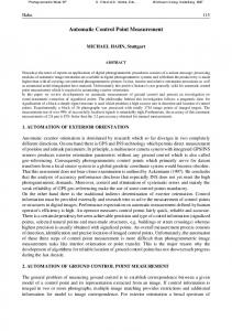
generation of the actual current cycle, and then stops the acquisition by throwing the event stop_cycle. The task Stop_Acquisition triggers a new execution of Set_Next_Cycle that restarts the loop up until the last scheduled current cycle or enables the Data_Conversion to format the output data. In Fig. 13, the result of the measurement is graphically shown by referring to a series of current cycles starting from 0 up to 10 (A) and their corresponding magnetic field from 0 to 6000 (A/m). The right trend of the hysteresis curve of the iron specimen highlights the validity of the proposal. IV. C ONCLUSION PNs have been shown to be an appropriate formalism to manage asynchronous measurement task scheduling. The method
presented in this paper turns out to be suited to assuring a proper software synchronization to the test procedure because it allows the temporal dimension to be abstracted from a flat description of the sequences of events by discovering the actual temporal relations between the events. In particular, the proposed Synchronizer allows a test engineer, without software skill, to schedule concurrent, sequential, and event-based tasks through an intuitively approach by thinking, into the time domain, in terms of simple relation like “after that” or “at same time of.” This approach was tested on-field in the permeability measurement of FFMMs at CERN. The main advantage is the simplification of the measurement script and the speeding up of its making. As a consequence, the test engineer can concentrate his attention on the measurement matters and not care about software design and programming details like threads and
ARPAIA et al.: PETRI NET-BASED SOFTWARE SYNCHRONIZER FOR AUTOMATIC MEASUREMENT SYSTEMS
Fig. 13. Hysteresis curve of the material.
semaphores. The corresponding satisfying results motivated a wide use of the proposed Synchronizer in other measurement layouts at CERN. ACKNOWLEDGMENT The authors would like to thank F. Cennamo for his useful suggestions and L. Walckiers, M. Buzio, V. Inglese, and G. Montenero for their precious collaboration. R EFERENCES [1] R. K. Gupta, C. N. Coelho, and G. De Micheli, “Synthesis and simulation of digital systems containing interacting hardware and software components,” in Proc. 29th ACM/IEEE Des. Autom. Conf., 1992, pp. 225–230. [2] G. Graunke and S. Thakkar, “Synchronization algorithms for sharedmemory multiprocessors,” Computer, vol. 23, no. 6, pp. 68–69, Jun. 1990. [3] C. von Praum, H. W. Cain, J. Choi, and K. D. Ryu, “Conditional memory ordering,” in Proc. 33rd IEEE ISCA, 2006, pp. 41–52. [4] P. Arpaia, M. L. Bernardi, G. Di Lucca, V. Inglese, and G. Spiezia, “An aspect oriented-based architectural framework for synchronization in measurement systems,” in Proc. 16th IMEKO TC4 Symp., Sep. 2008. [5] A. Birrell, J. Guttag, J. Horning, and R. Levin, “Synchronization primitives for a multiprocessor: A formal specification,” in Proc. 11th ACM Symp. Operating Syst. Principles, Austin, TX, Nov. 8–11, 1987, pp. 94–102. [6] D. Reed and R. Kanodia, “Synchronization with event counts and sequencers,” MIT Lab. Comput. Sci., Cambridge, MA, 1977. [7] T. E. Anderson, B. N. Bershad, E. D. Lazowska, and H. M. Levy, “Scheduler activations: Effective kernel support for the user-level management of parallelism,” ACM Trans. Comput. Syst. (TOCS), vol. 10, no. 1, pp. 53–79, Feb. 1992. [8] T. Murata, “Petri nets: Properties, analysis and applications,” Proc. IEEE, vol. 77, no. 4, pp. 541–580, Apr. 1989. [9] J. Bosch, “Design of an object-oriented framework for measurement systems,” in Domain-Specific Application Frameworks, M. Fayad, D. Schmidt, and R. Johnson, Eds. Hoboken, NJ: Wiley, 1999, pp. 177–205. [10] B. Stoyanov, S. Stefanov, J. Beyazov, and V. Peichev, “Contemporary methods and devices for automatic measurement,” Problems Eng. Cybern. Robot., vol. 57, pp. 79–86, 2006. [11] [Online]. Available: http://www.tango-controls.org/ [12] J. M. Nogiec, J. Di Marco, S. Kotelnikov, K. Trombly-Freytag, D. Walbridge, and M. Tartaglia, “Configurable component-based software system for magnetic field measurements,” IEEE Trans. Appl. Supercond., vol. 16, no. 2, pp. 1382–1385, Jun. 2006. [13] L. Ding and Y. Shen, “Real time performance analysis and evaluation of CAN bus with an extended Petri Net model,” in Proc. IEEE I2MTC, Singapore, May 5–7, 2009, pp. 1081–1084.
327
[14] M. R. Frankowiak, R. I. Grosvenor, and P. W. Prickett, “A Petri-net based distributed monitoring system using PIC microcontrollers,” Microprocess. Microsyst., vol. 29, no. 5, pp. 189–196, Jun. 1, 2005. [15] V. Calderaro, V. Galdi, A. Piccolo, and P. Siano, “DG and protection systems in distribution network: Failure monitoring system based on Petri nets,” in Proc. Bulk Power Syst. Dyn. Control—VII. Revitalizing Operational Rel., iREP Symp., Aug. 19–24, 2007, pp. 1–7. [16] C. N. Hadjicostis and G. C. Verghese, “Power system monitoring using Petri net embeddings,” Proc. Inst. Elect. Eng.—Gener., Transmiss. Distrib., vol. 147, no. 5, pp. 299–303, Sep. 2000. [17] Z. Huiqin, G. Jun, X. Youbao, and L. Wei, “Modeling and analysis of a testing system using hybrid petri net,” in Proc. 8th ICEMI, Aug. 16–18, 2007, pp. 1-465–1-470. [18] W. Xiaoli, C. Guangju, X. Yue, and G. Zhaoxin, “Fault detection and diagnosis based on time Petri net,” in Proc. 8th ICEMI, Aug. 16–18, 2007, pp. 3-259–3-263. [19] G. Lindner, M. Heiner, and T. Kobienia, “Deadlock detection in a distributed implementation of a visualization system for medical measurement signals,” in Proc. IEEE Int. Conf. Syst., Man, Cybern., Oct. 14–17, 1996, vol. 3, pp. 2299–2304. [20] R. Lukaszewski and W. Winiecki, “Petri nets in measuring systems design,” IEEE Trans. Instrum. Meas., vol. 57, no. 5, pp. 952–962, May 2008. [21] P. Bilski and R. Lukaszewski, “Petri nets model of DAQ block in the measurement system,” in Proc. IEEE Int. Workshop Intell. Data Acquisition Adv. Comput. Syst.: Technol. Appl., Dortmund, Germany, Sep. 6–8, 2007, pp. 268–273. [22] Y. E. Papelis and T. L. Casavant, “Specification and analysis of parallel/distributed software and systems by Petri nets with transition enabling functions,” IEEE Trans. Softw. Eng., vol. 18, no. 3, pp. 252–261, Mar. 1992. [23] P. Arpaia, L. Bottura, M. Buzio, D. Della Ratta, L. Deniau, V. Inglese, G. Spiezia, S. Tiso, and L. Walckiers, “A software framework for flexible magnetic measurements at CERN,” in Proc. IEEE Instrum. Meas. Technol. Conf., May 1–3, 2007, pp. 1–4. [24] P. Arpaia, L. Bottura, V. Inglese, and G. Spiezia, “On-field validation of the new platform for magnetic measurements at CERN,” Measurement, vol. 42, no. 1, pp. 97–106, Jan. 2009. [25] P. Arpaia, M. Buzio, L. Fiscarelli, V. Inglese, and G. La Commara, “Automatically generated user interfaces for measurement software frameworks: A case study on magnet testing at CERN,” in Proc. XIX IMEKO World Congr., Fundam. Appl. Metrology, Lisbon, Portugal, Sep. 6–11, 2009. [26] M. Woodside, Software Performance Evaluation by Models. Berlin, Germany: Springer-Verlag. [27] G. Topic, D. Jevtic, and M. Kunstic, Petri Net-Based Simulation and Analysis of the Software Development Process. Berlin, Germany: Springer-Verlag. [28] M. Zhou and K. Venkatesh, Modeling, Simulation, and Control of Flexible Manufacturing Systems: A Petri Net Approach. Singapore: World Scientific, 1999, ser. Series in Intelligent Control and Intelligent Automation. [29] S. Kumanan and K. Raja, “Modeling and simulation of projects with Petri nets,” Amer. J. Appl. Sci., vol. 5, no. 12, pp. 1742–1749, 2008. [30] J. Billington, M. Diaz, and G. Rozenberg, Application of Petri Nets to Communication Networks. New York: Springer-Verlag, 1999. [31] J. Cortadella, M. Kishinevsky, A. Kondratyev, L. Lavagno, and A. Yakovlev, “Petrify: A tool for manipulating concurrent specifications and synthesis of asynchronous controllers,” IEICE Trans. Inf. Syst., vol. E80-D, no. 3, pp. 315–325, 1997. [32] P. Arpaia, M. Bernardi, G. Di Lucca, V. Inglese, and G. Spiezia, “An aspect oriented programming-based approach to software development for measurement system fault detection,” Comput., Standards Interfaces, vol. 32, no. 3, pp. 141–152, Mar. 2010. DOI: 10.1016/j.csi.2009.11.009. [33] P. Arpaia, M. Bernardi, G. Di Lucca, V. Inglese, and G. Spiezia, “Aspect oriented-based software synchronization in automatic measurement systems,” in Proc. IEEE IMTC, 2008, pp. 1718–1721. [34] K. N. Henrichsen, “Permeameter,” in Proc. 2nd Int. Conf. Magnet Technol., Oxford, U.K., 1967, pp. 735–739. [35] [Online]. Available: http://sine.ni.com/nips/cds/view/p/lang/en/nid/1037 [36] P. Arpaia, A. Masi, and G. Spiezia, “A digital integrator for fast accurate measurement of magnetic flux by rotating coils,” IEEE Trans. Instrum. Meas., vol. 56, no. 2, pp. 216–220, Apr. 2007. [37] P. Arpaia, M. Buzio, L. Fiscarelli, V. Inglese, and G. La Commara, “Measurement-domain specific language for magnetic test specifications at CERN,” in Proc. IEEE I2MTC, Singapore, May 5–7, 2009, pp. 1716–1720.
328
IEEE TRANSACTIONS ON INSTRUMENTATION AND MEASUREMENT, VOL. 60, NO. 1, JANUARY 2011
Pasquale Arpaia was born in Napoli, Italy, on February 2, 1961. He received the M.D. and Ph.D. degrees in electrical engineering from the University of Napoli Federico II, Napoli. He was a member of the Scientific and Administration Council of the new thematic University of Science and Technology, University of Napoli Federico II. Since 2001, he has been an Associate Professor with the University of Sannio, Benevento, Italy. Since August 2005, he has been a Project Associate with the Large Hadron Collider (LHC), European Organization for Nuclear Research (CERN). He was a Consultant on the EU IV Framework Program “Standard Measurement and Testing” and an Evaluator for EU INTAS projects. With H. Schumny, he was responsible for the Promoting Committee of the EUPAS Project of the IMEKO TC-4 “A/D and D/A Metrology” WG and is a voting member of the IEEE IM TC-10 “Waveform Measurement and Analysis” and of the IEC TC-47. He was also the Associate Editor for the Subject Areas “Quality and Statistical Methods” and “Test” of the IEEE TRANSACTIONS ON ELECTRONICS PACKAGING AND MANUFACTURING. He is Editor of the Subject Area “Digital Instruments Standardization” for the Elsevier Journal Computer Standards and Interfaces. He organized several international meetings in the field of electronic measurements and European cooperation. His main research interests include digital instrumentation and software frameworks for magnetic measurements in particle accelerators, evolutionary diagnostics, ADC modeling, testing, and standardization, measurement systems on geographic networks, and statisticalbased characterization of measurement systems. In these fields, he published more than 130 scientific papers in journals and national and international conference proceedings.
Lucio Fiscarelli was born in Benevento, Italy, in June, 1979. He received the M.D. degree in telecommunication engineering in October 2008 from the University of Sannio, Benevento. He is currently working toward the Ph.D. degree with the Department of Engineering, University of Sannio, Benevento, Italy. His thesis on the development of the flexible framework for magnetic measurements was carried out in the Department AT/MTM, CERN, from June 2008 to October 2008. He is developing his research activities with the Department TE/MSC, CERN. His main research interests include softwarebased measurement systems and magnetic measurements on particle accelerators.
Giuseppe La Commara was born in Napoli, Italy, on September 14, 1971. He received the M.D. degree in software engineering from the University of Napoli Federico II, Napoli. From 1999 to 2005, he worked on several European research projects with Tecnoret Research Centre. In 2005, he began a scientific collaboration with the University of Sannio, Benevento, Italy. From 2007 to 2009, he also was an Unpaid Associate with the Large Hadron Collider (LHC), European Organization for Nuclear Research (CERN). His main research interests include software frameworks for magnetic measurements in particle graphical interface automatic generation, domain-specific language, and model-driven engineering.
Felice Romano was born in Pomigiano d’Arco (Napoli), Italy, on January 10, 1980. He received the M.D. degree in computer science from the University of Napoli Federico II, Napoli, Italy. From the 2005 to 2006, he was an Intern with the “Software Testing and Quality Assurance” Team, Software Design Center, STMicroelectronics. In 2007, he was a Consultant in the design, development, and maintenance of J2EE-based software with Reply S.P.A. In 2008, he began a scientific collaboration with the University of Sannio, Benevento, Italy. In 2009, he also was an Unpaid Associate with the Large Hadron Collider (LHC), European Organization for Nuclear Research (CERN).