ARTICLE DE FOND
A PHOTONICS PATH
TO
STRUCTURAL MONITORING
FABIEN RAVET AND XIAOYI BAO
BY
I
n 1920, when Leon Brillouin presented his thesis “Diffusion de la lumière et des rayons X par un corps transparent et homogène – Influence de l’agitation thermique1”, he probably did not suspect that his discovery would still generate passionate interest in the twenty first century [1]. His research led to the conclusion that density fluctuations in the medium resulted in thermally generated sound waves. That thermal agitation is capable of scattering incident lightwave inelastically, i.e. the scattering has shifted frequency2. In 1930, Gross’s experiments [2] showed that the scattered spectra included two Brillouin components and one unshifted peak (Fig. 1), the so called Rayleigh scattering. The Brillouin peaks are the Stokes and the anti-Stokes lines, which are down- and upshifted in frequency, respectively. These frequency shifts are proportional to the acoustic mode velocity and are called Brillouin frequency, i.e. the broadening of the peaks is due to the attenuation of the sound waves. Landau and Placzek (1934) explained that the central line is due to non-propagating temperature fluctuations [2,3]. The field then did not really progress due to the lack of intense monochromatic sources and sensitive spectrometers. The advent of the laser (circa 1964) brought new advances to the topic [4]. With the development of high-resolution spectrum analysers, accurate measurements of the frequencies, intensities and linewidths of the various lines are possible giving access to the characterisation of acoustic and thermodynamic properties of materials e.g. sound velocity, sound attenuation coefficients, elastic constants, and isothermal compressibility. These properties are still studied with the help of Brillouin scattering [5]. The seventies saw the introduction of optical fibres and the first
SUMMARY Disaster prevention in civil infrastructures requires the use of techniques that allow temperature and strain measurements in real time over lengths of a few meters to tens of kilometres. The distributed Brillouin sensor (DBS) technique has the advantage to combine all these characteristics. The sensing mechanism of the DBS involves the interaction of two counter-propagating lightwaves, the Stokes and the pump, in an optical fibre. In this article, we introduce the DBS physics and illustrate how it can be used in civil and structural engineering.
observations of spontaneous and stimulated Brillouin scattering in silica waveguides [6,7]. Here the interest was triggered by the impairment caused by the stimulated Brillouin scattering in transmission links [8]. Since then, the interest never ceased, as many potential applications of Brillouin scattering in optical fibres were investigated. We can mention optical amplifiers [9], fibre lasers [10], narrowband and tuneable filtering [11]. More recently, researches have shown that the propagation time of pulses in optical fibres can be controlled thanks to the Brillouin resonance[12,13]. Among all these applications, we retain the works of Horiguchi and Culverhouse, both in 1989, where the authors demonstrated that Brillouin scattering can be used to measure strain and temperature respectively, initiating a prolific research in fibre optic sensors [14,15].
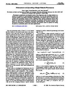
Fig. 1
Schematic of the observed scattered light intensity. Frequency and intensity axis are not scaled to reproduce accurately the peaks heights and frequencies.
STRUCTURAL HEALTH MONITORING The sensing capabilities of Brillouin scattering are certainly of interest for civil engineering applications where a new field, known as Structural Health Monitoring (SHM), is currently developing. According to Bisby [16], “….structural health monitoring can be defined as a nondestructive in-situ structural evaluation method that uses any of several types of sensors which are attached to, or embedded in, a structure. These sensors obtain various types of data (either continuously or periodically), which are then collected, analyzed and stored for future analysis and reference. The data can be used to assess the safety, integrity, strength, or performance of the structure, and to identify damage at its onset.” Various factors have driven the emergence of SHM. First, public infrastructures of industrialised countries are subjected to a strong “pres-
Fabien Ravet* and Xiaoyi Bao (
[email protected]), Canada Research Chair in Fibre Optics and Photonics, Physics Department, University of Ottawa, 150 Louis Pasteur, Ottawa, ON, K1N 6N5 * current address: Omnisens SA, 3 Riond Bosson, CH-1110 Morges, Switzerland,
1. The thesis can be translated as “Light and x-rays scattering by a transparent homogeneous body – Effect of thermal agitation”. The work was published as an article in 1922 (Brillouin 1922). 2. The same effect was studied independently by Mandelstham and published in 1926 (Schroeder 1977).
LA PHYSIQUE AU CANADA / Vol. 64, No. 1 ( jan. à mars (hiver) 2008 ) C 13
... STRUCTURAL MONITORING (RAVET AND BAO)
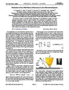
sure” on ‘safety’. Civil structures are overused, leading to accelerated ageing. Moreover, the infrastructures are often old not to say obsolete e.g. 40% of the bridges in Canada are 50 years old [16]. In many cases, replacement is not immediately possible due to a lack of public funding. Instead, strengthening and rehabilitation are considered as an option that would increase the lifetime of the current infrastructure. Determining the lifetime of the structure is then critical, which is only possible if an inspection strategy is in place. SHM can then be implemented to identify early signs of potential problems, allowing for prevention of disasters and repair of the damage. Second, SHM is also a tool to improve the construction processes for new building materials and structures. These innovative structures response to stress can be studied thanks to a systematic layout of sensors and to the monitoring of their outputs. One of the most spectacular and recent example is certainly the Confederation Bridge (Fig. 2).
Fig. 2
Confederation bridge: an example of structure combining innovative design and SHM techniques.
FIBRE OPTIC SENSORS Among the various sensing technologies that are considered for SHM, fibre optic sensors (FOS) are the most promising candidates [17-20]. Their advantages are inherent to the optical fibre properties. Being made of silica, the sensing medium is made of dielectric materials, which are immune to electromagnetic interferences. The sensors can be installed in remote locations as the fibre is a low loss transmission medium. Fibre optic sensors are small, light and non-corrosive, implying that they can be embedded without impacting significantly the structure design. Finally, optical fibre technology is now a field mature enough so that the sensors can be laid on any structure shape and size i.e. a broad variety of optical components allows the multiplexing and the cascading of sensors. In addition, that capability is enhanced by the sensor type. In fact, FOS can be divided into two categories: point and distributed sensors. For point sensor, the sensing length (or gauge length) varies from centimetres to tens of meters. The sensing part is connected to the light source and the detection system by an optical fibre communication cable. In this category we find fibre Bragg gratings (FBG) and Fabry-Perot (FP) sensors. Long gauge (LG) sensors, which are based on a Michelson interferometer
design, measure average strain over the gauge length, which can be as large as 200 m. In the case of distributed FOS, the fibre itself is the sensing medium, at any location, and the gauge length can be as small as tenths of metres over distances as long as tens of kilometres. The monitoring techniques must be able to detect faults and assess the severity of the damage of whole structures such as pipelines, bridges, dams or river levees. Ideally, the sensors must perform distributed temperature or/and strain measurements over a few meters to tens of kilometres in real time. Those requirements can easily be met by the use of distributed sensors.
DISTRIBUTED SENSORS Three physical effects are identified as mechanisms for distributed sensing: Rayleigh, Raman and Brillouin scattering. The simplest distributed sensor is based on Rayleigh scattering and is widely used in optical communications to qualify optical links [21]. It is known as the optical time domain reflectometer (OTDR). As the Rayleigh peak temperature dependence in normal fibres is weak, its implementation as a sensor requires the development of non-standard fibres3. These fibres have a liquid core [22], or, special core dopants that makes the Rayleigh peak more sensitive to temperature changes [23]. Special cables can also be used that convert the physical quantity (temperature, strain, pressure) variation into excess loss[24]. Raman scattering is another effect that can be exploited to measure temperature over 10 kilometres to the maximum [25]. Here, the sensing function is achieved by computing the ratio of the measured Stokes to anti-Stokes intensities, as it is an exponential function of temperature. At last but not least is the Brillouin sensor technique, which is capable of measuring both temperature [14] and strain [15] up to 50 km kilometres without signal regeneration [26]. In the Brillouin sensor, the sensing mechanism takes advantage of the linear relationship between the Brillouin frequency and temperature/tensile strain variations (Fig. 3). The Brillouin sensor has clearly an advantage over the other technologies as it can perform temperature and
Fig. 3
The Brillouin frequency is proportional to temperature and strain.
3. The adjective “standard” used in the present article refers to optical fibres that are used in optical communications and whose nominal characteristics are determined by standardization bodies such as the International Telecommunication Union or the International Electrotechnical Committee.
14 C PHYSICS
IN
CANADA / VOL. 64, NO. 1 ( Jan.-Mar. (Winter) 2008 )
... STRUCTURAL MONITORING (RAVET ET BAO)AA
strain measurement. Brillouin sensor classification can be refined further by considering the configuration of the sensor. Two layouts can be distinguished which are Brillouin backscattering and stimulated Brillouin scattering configurations. We will focus our attention on the stimulated Brillouin scattering configuration.
STIMULATED BRILLOUIN SCATTERING CONFIGURATION In the stimulated Brillouin scattering configuration, two lightwaves, the pump and the probe signals, are launched into the fibre in a counter-propagating configuration. The simultaneous presence of the Stokes and the pump waves generate a beat signal that reinforces the acoustic wave in the fibre when the beams frequency difference is equal to the Brillouin frequency. The coupling mechanism between the two lightwaves is electrostriction, which is the ability of a centro-symmetric material to change density when an electric field is applied. The scattering of the pump is then enhanced, leading to its depletion and the input probe beam is amplified. The probe is also called Stokes as it corresponds to the frequency downshifted peak. The Brillouin spectrum can be recorded by tuning the frequency difference between pump and Stokes waves. In our sensing configuration, distributed information is obtained by pulsing one of the two light sources, the sensor is called Brillouin optical time domain analyser (BOTDA) [27]. The pulsewidth determines the spatial resolution of the sensor and then its gauge length. The signal detection is performed at the fibre end in which the modulated lightwave is launched. The sensor configuration used at the university of Ottawa is based on the Brillouin loss type BOTDA [27-29] and is presented in Fig. 4. In that configuration, the Stokes wave is pulsed and the sensor records the pump output intensity variation. The pump is then attenuated at the profit of the Stokes signal.
smallest detectable event size, the frequency resolution, which is the smallest Brillouin frequency shift that can be measured, and the measurement range, which is the longest length over which the sensor can make an accurate data acquisition.
EXAMPLES OF APPLICATIONS The first pipe case studied was the monitoring of a distribution pipe subjected to extreme load conditions [30,31]. In that experiment a vertical load was applied to the structure. Buckling occurred at the current loading level because the inner wall was locally thinned to create a weakness that would act as a failure trigger (Fig. 5). The buckling formation could be anticipated by watching for multiple strain components over the pulse length, especially at the tension site. Those components lead generally to multiple peak Brillouin spectra Fig. 5 Buckled pipe with at the buckling location sensing fibres (brow (Fig. 6). strips).
PERFORMANCE PARAMETERS Various parameters need to be considered when comparing the Brillouin sensor systems. First, one has to keep in mind that the sensor must be implemented on the field. It must then be simple to install and complete the sensing operation as quickly as possible. Second, some of the sensor performances are critical. Those are the spatial resolution, which indicates the
Fig. 4
Experimental set-up of the distributed Brillouin sensor.
Fig. 6
Brillouin spectrum measured at buckling location.
We conducted another monitoring experiment on a concrete column strengthened with fibre reinforced polymer sheets [3234]. The column was subjected to an axial load while successively bended back- and forward with increasing loads, simulating seismic induced stress conditions. For a concrete/FRP (fibre reinforced polymer) column, the structure is non uniform and inhomogeneous by construction. Even a light stress would induce quite a large Brillouin spectrum distortion. The spectra would appear asymmetric and broadened. We developed an approach based on the spectrum shape analysis to analyse the structure behaviour [33]. We see that our sensor system is not only capable of measuring deformation of the structure as illustrated in Fig. 7. It also gives enough information so that engineers can correlate the readings with the applied stresses and deduce the possible de-bonding of the FRP and concrete as well as the crack conditions (Fig. 8).
LA PHYSIQUE AU CANADA / Vol. 64, No. 1 ( jan. à mars (hiver) 2008 ) C 15
... STRUCTURAL MONITORING (RAVET AND BAO)
Fig. 7
Axial profile of peak strain for (a) left face and (b) right faces under respectively a left and right horizontal loads. Open symbol curves correspond to a lateral displacement of 8% of the column height and full symbols are associated with a deviation of 4%.
CONCLUSIONS Following two recent bridge fallings: 1) On September 30, 2006, part of an overpass (65 foot section of a three-lane overpass collapsed in Laval, a suburb of Montreal, on Concorde boulevard running over Autoroute 19. The collapse crushed two vehicles under it, killing five people and seriously injuring six others who went over the edge while travelling on the overpass. The bridge was inspected in 2005 without major problem. 2) A major highway bridge in Minneapolis buckled during rush hour on Wednesday night (August 1, 2007), forcing dozens of cars to plummet into the Mississippi River. The Minnesota governor said a 2006 inspection of the bridge found no immediate structural problems. Both events show the importance of improving the state of the practice for bridge management via an accurate assessment of bridge condition and performance. This can only be achieved by better understanding the bridge condition through developing advanced health monitoring tools comprising both remote and onsite evaluation and distributed Brillouin sensor is one of the most promising tools to serve the need of the structural health monitoring for bridge and other large civil structures. Finally we need to relate health monitoring findings to structural condition.
Fig. 8
Post-mortem analysis of the column: concrete at the bottom part has been crushed; once FRP is removed, concrete dust flown on the column support.
The purpose of the structural health monitoring is to protect and prolong the useful life of structures, and to identify problems & trigger follow-up action (Condition survey, evaluation, etc), as well as to gather enough information to estimate bridge rehabilitation and maintenance needs. This requires engineers and scientists from different fields work together to ensure an acceptable standard for structures in terms of public safety, comfort and convenience.
Distributed Brillouin sensors, whose operation principles were described in this article, are one of the most promising diagnostic tools that could help improve the structural health monitoring process. Their insensitivity to the harsh environmental conditions, along with the low investment costs required for their integration into the new or existing infrastructures, makes them an ideal candidate for structural health monitoring applications
ACKNOWLEDGEMENT The authors want to acknowledge the financial support of Natural Science and Engineering Research Council Canada, Intelligent Sensing for Innovative Structures Canada, whose funding was appreciated very much.
REFERENCES 1. 2. 3. 4. 5. 6. 7. 8.
Brillouin, L., “Diffusion de la lumière et des rayons X par un corps transparent homogène”, Annales de Physique, 17: 88-122 (1922). Schroeder, J., “Light scattering of glass”, Treatise on material science and technology, Volume 12. Glass I: interaction with electromagnetic radiation, Academic Press: 157-222 (1977). Landau, L., and, Lifchitz, E., Electrodynamique des milieux continus, Editions Mir, Moscou (1969). Chiao, R.Y., Townes, C.H., and Stoicheff, B.P., “Stimulated Brillouin Scattering and Coherent Generation of Intense Hypersonic Waves”, Physical Review Letters 12: 592-595 (1964). Levelut, C., Le Parc, R., and Pelous, J., “Dynamic sound attenuation at hypersonic frequencies in silica glass”, Physical Review B, 73: 052202 (2006). Ippen, E.P., and Stolen, R.H., “Stimulated Brillouin scattering in optical fibers”, Applied Physics Letters 21: 539-541 (1972). Rich, T.C., and, Pinnow, D.A., “Evaluation of fiber optical waveguides using Brillouin spectroscopy”, Applied Physics Letters 13: 264266 (1974). Smith, R.G., “Optical power handling capacity of low loss optical fibers as determined by stimulated Raman and Brillouin scattering”, Applied Optics, 11: 2489-2494 (1972).
16 C PHYSICS
IN
CANADA / VOL. 64, NO. 1 ( Jan.-Mar. (Winter) 2008 )
... STRUCTURAL MONITORING (RAVET ET BAO)AA
9. 10. 11. 12. 13. 14. 15. 16. 17. 18. 19. 20. 21. 22. 23. 24. 25. 26. 27. 28. 29. 30. 31. 32. 33. 34.
Olsson, N.A. and van der Ziel, J.P., “Cancellation of fiber loss by semiconductor laser pumped Brillouin amplification at 1.5 ?m”, Applied Physics Letters, 48: 1329-1330 (1986). Bayvel, P., Giles, I.P., and Radmore, P.M., “Transients and steady-state characteristics of a Brillouin amplifier based on an all-fibre single-mode ring resonator”, Optical and Quantum Electronics, 21: S113-S128 (1989). Tkach, R.W., Chraplyvy, A.R., and Derosier, R.M., “Performance of a WDM network based on stimulated Brillouin scattering”, IEEE Photonics Technology Letters, 21: S105-S112 (1989). Okawachi, Y., Bigelow, M.S., Sharping, J.E., Zhu, Z., Schweinberg, A., Gauthier, D.J., Boyd, R.W., and, Gaeta, A.L., “Tunable alloptical delays via Brillouin Slow Light in an Optical Fiber”, Physical Review Letters, 94: 153902 (2005). Song K.-Y., González-Herráez, M., and Thévenaz, L., “Observation of pulse delaying and advancement in optical fibers using stimulated Brillouin scattering”, Optics Express, 13: 82-88 (2005). Horiguchi, T., Kurashima, T. and Tateda, M., “Tensile strain of Brillouin frequency shift in silica optical fibers”, IEEE Photonics Technology Letters, 1: 107-108 (1989). Culverhouse, D., Frahi, F., Pannell, C.N., and, Jackson, D.A, “Potential of stimulated Brillouin scattering as sensing mechanism for distributed temperature sensor”, Electronics Letters, 25: 913-915 (1989). Bisby, L.A., ISIS educational module 5: an Introduction to structural health monitoring, ISIS Canada (2004). Kersey, A.D., “A review of recent developments in fiber optic sensor technology”, Optical Fiber Technology, 2: 291-317 (1996). Tennyson, R.C., Coroy, T., Duck, G., Manuelpillai, G., Mulhivill, P., Cooper, D.J.F., Smith, P.W.E., Mufti, A.A., and, Jalali, J.J., “Fibre optic sensors in civil engineering structures”, Canadian Journal of Civil Engineering, 27: 880-889 (2000). Culshaw, B., “Optical fiber sensor technologies: opportunities and-perhaps-pitfalls”, Journal of Lightwave Technology, 22: 39-50 (2004). Thévenaz, L., “Review and progress in distributed fiber sensing”, 18th International Conference on Optical Fibre Sensors OFS 2007, Cancun (Mexico), October 23-27, 2006, Technical Digest of the Optical Society of America, Paper ThC6 (2006). Hartog, A.H., and Gold, M.P., “On the theory of backscattering in single-mode optical fibers”, Journal of Lightwave Technology, 2: 76-84 (1984). Hartog, A.H., “A distributed temperature sensor based on a liquid-core optical fibre”, Journal of Lightwave Technology, 1, 498 (1983). Farries, M.C., Fermann, M.E., Laming, R.I., Poole, S.B. and Payne, D.N., “Distributed temperature sensor using Nd3+ doped fiber”, Electronics Letters, 22: 418-419 (1986). Maclean, A., Moran, C., Johnstone, W., Culshaw, B., Marsh, D., and Parker, P., “Detection of hydrocarbon fuel spills using a distributed fibre optic sensor”, Sensors&Actuators: A. Physical, 109: 60-67 (2003). Dakin, J.P., Pratt, D.J., Bibby, G.W., and Ross, J.N., “Distributed optical Raman temperature sensor using a semiconductor light source and detector”, Electronics Letters, 21: 569-570 (1985). Bao, X., Dhliwayo, J., Heron, N., Webb, D.J., and Jackson, D.A. “Experimental and theoretical studies on a distributed temperature sensor based on Brillouin scattering”, Journal of Lightwave Technology, 13: 1340-1348 (1995). Horiguchi, T., and Tateda, M.Y., “BOTDA-nondestructive measurement of single-mode optical fibers attenuation characteristics using Brillouin interaction: theory”, Journal of Lightwave Technology, 7: 1170-1176 (1989). Bao, X., Webb, D.J., and Jackson, D.A., “32-km distributed temperature sensor based on Brillouin loss in an optical fiber”, Optics Letters, 18: 1561-163 (1993). Bao, X., Webb, D.J, and Jackson, D.A., “ombined distributed temperature and strain sensor based on Brillouin loss in an optical fiber”, Optics Letters, 19: 141-143 (1994). Ravet, F., Zou, L., Bao, X., Chen, L., Huang, R.F., and Khoo, H.A., “Pipeline buckling detection by the distributed Brillouin sensor”, Sensing Issues in Civil Structural Health Monitoring, Farhad Ansari Editor, Springer Verlag: 515-523 (2005). Ravet, F., Zou, L., Bao, X., Chen, L., Huang, R.F., and Khoo, H.A., “Detection of buckling in steel pipeline and beam by the distributed Brillouin sensor”, Optical Fiber Technology, 12: 305-311 (2006). Ozbakkaloglu, T. and Saatcioglu, M., “Seismic performance of square high-strength concrete columns in FRP stay-in-Place formwork”, Journal of Structural Engineering, 133: 44-56 (2007). Ravet, F., Bao, X., Ozbakaloglu, T., and Saatcioglu, M., “Signature of structure failure using asymmetric and broadening factors of Brillouin Spectrum”, IEEE Photonics Technology Letters, 18: 394-396 (2006). Ravet, F., Zou, L., Bao, X., Ozbakkaloglu, T., Saatcioglu, M., and Zhou, J., “Distributed Brillouin sensor for structural health monitoring”, Canadian Journal of Civil Engineering, 34: 291-297 (2007).
LA PHYSIQUE AU CANADA / Vol. 64, No. 1 ( jan. à mars (hiver) 2008 ) C 17