measurement equipment. Since the ... The written construct is used to incorporate a history and revision mechanism into PIF, allowing to .... Int. at Unterpremstatten, Austria; DIGITAL EQUIPMENT Corp. at Hudson, USA; SIEMENS. Corp. at ...
SIMULATION OF SEMICONDUCTOR DEVICES AND PROCESSES Vol. 4 Edited by W. Fichlner, D. Aemmer - Zurich (Switzerland) September 12-14,1991 - Hartung-Gorre
A PIF Implementation for TCAD Purposes F. Fasching, C. Fischer, S. Selberherr, H. Stippel, W. Tuppa institute for MicroeJectronics, Technical University of Vienna, Austria H. Read ECE Department, Carnegie Mellon University, Pittsburgh, PA, USA
Abstract The implementation of the Profile Interchange Format (PIF) for Technology CAD (TCAD) purposes is demonstrated. An application program interface for use with process and device simulation tools coded in FORTRAN, C and LISP is presented, capable of performing convenient, fast and flexible access to an extendable binary data format which fulfills todays and future needs for physical and logical TCAD information exchange.
1
Introduction
Recent developments have proven the need for integrating process and device simulation tools i n t o a common environment to allow centralized simulation control and information exchange. I n order to aid the integration of those tools, a common interchange format for simulation and measurement data has been proposed in [1]. This proposal of a textual PIF has stimulated other work on a binary PIF implementation (e.g. [2]). Although those implementations are rigorous i n terms of functional orthogonality for C and LISP applications, they lack access speed and operating system independence as well as a FORTRAN interface. We extended the textual P I F for the use in TCAD environments, developed a flexible binary format and implemented a fast and operating system independent programming interface for FORTRAN, C and LISP applications (see [3], [4]).
2
The Intersite PIF
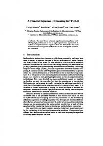
T h e intersite (textual, ASCn) form of the PIF is used to exchange simulation and measurement d a t a between sites via eletronic mail or the file transfer protocol. The original intention was t o allow the transfer of geometry, grid and attribute information between simulators and/or measurement equipment. Since the expectations in integrated simulation systems are growing continuously, just simply coupling the tools is not enough. We extended the PLF syntax to accommodate the needs of TCAD applications; thus additional information relevant to the environment can be incorporated in the PIF. The basic needs of an interchange format are fulfilled with the geometry, g r i d and a t t r i b u t e constructs, shown in Fig. 1. Geometries can be specified either hierarchically or nonhierarchically, using various list constructs to build up primitive and physical geometric objects. A necessary functionality for TCAD applications is the ability to use an arbitrary number o f dimensions for the points, and different - even nonspatial - units for each dimension. This
478
PIF PI F objects PIF object groups
snapshot
111
nameList
objectGroup
lliliiill
written
pointList lineList faceList solidUst
segmentUst boundaryUst
meta
r-
„
userData
\
comment
^
^
PIF geometric objects PIF primitive geometric objects PIF physical geometric objects Figure 1: The logical PIF structure allows e.g. the incorporation of points into a multidimensional parameter space for optimization purposes. Grids can be defined over physical geometric objects, but in contrast to other approaches both grids consisting of arbitrary elements (defined with primitive geometric objects) and orthogonal grids (defined with the orthoProduct construct) can be stored in the PIF. Both geometry and grid constructs have a grouping function, i.e. they gather other PIF objects and give this group a special meaning. Other constructs with grouping functionality are the snapshot construct, grouping together PIF objects that relate to a certain time step or a distinct parameter set, and the objectGroup construct, providing just a logical grouping of objects with no explicitly defined meaning. Except from the nameList, the grouping constructs are PIF objects, implying that they have a name by which they can be referenced from other PIF objects. A t t r i b u t e s are very powerful PIF objects. They can be classified into physical or nonphysical attributes and concentrated or distributed attributes. Attributes are equipped with an attribute type which defines a (standardized) meaning of the attribute.
479
Physical attributes are used to describe all non-geometrical aspects of a simulation probl e m like boundary conditions, materialtype, electrical properties and to describe the solutions t o a problem like electric potential, charge density, doping profile and so on, which can be t h e input (physical problem description) to another simulation step. Physical attributs are m o s t l y nested: the upper level attribute tells which aspect of the physical problem is described. F o r example, this can be one of S e g m e n t D e s c r i p t i o n (physical properties of a segment), I m p u r i t y D e s c r i p t i o n , F i e l d D e s c r i p t i o n , BoundaryDescription, I n t e r f a c e D e s c r i p t i o n , C o n t a c t D e s c r i p t i o n or T e r m i n a l D e s c r i p t i o n . Within these toplevel attributes there are generic attributes like M a t e r i a l T y p e , C o n c e n t r a t i o n , or V e l o c i t y or more specific attributes l i k e E l e c t r i c P o t e n t i a l , I n t e r f aceValue or T e n a i n a l G u r r e n t (these are just a few examples). Non-physical attributes are used for different purposes. They are used to specify the CPU t i m e required to produce a given P I F object, to identify a set of objects with a simulation step I D , to define additional connections between elements of a mesh and many things more. All attributes should adhere to the semantical standardization of the A t t r i b u t e T y p e in o r d e r to enable different tools to interprete the things described by attributes in the right way. The w r i t t e n construct is used to incorporate a history and revision mechanism into P I F , allowing to track down the modification steps of a PIF file to its creation. This information includes the person (or program) who made changes to the P I F , the time, date and location as w e l l as references to the objects which have been changed. Any kind of information necessary for the TCAD system can be represented, be it a process flow representation or even a whole TCAD shell task program, as long as it conforms to a LISP s y n t a x . This is mainly achieved by the help of the meta construct. A comment construct is provided to specify comments which are also to be included in the i n t e r t o o l P I F . LISP-style comments are allowed anywhere in the intersite PEF, but they are i g n o r e d on converting the intersite to the intertool P I F . The u s e r D a t a construct is provided for the incorporation of nonstandard extensions to the P I F . It also implements full LISP syntax, but should be avoided wherever possible.
3
The Intertool PIF
T h e intertool (binary) form of the P I F allows for fast and compact information sharing at o n e site. In order to retain the full flexibility of the intersite format even in its binary mode, d a t a structures have been developed which provide for a close bijective representation of LISP p r i m i t i v e s . Thus any datum expressible in LISP notation can be stored in the binary file. Fig. 2 s h o w s the available primitives which can be combined into (even compressed) arrays and linked t o g e t h e r . Additionally, a symbol hash table maintained in the binary P I F file enables fast access t o named P I F objects. One binary P I F file can hold a virtually unlimited number of logical P I F units, with one logical P I F unit being a P I F file in the sense of [1].
4
The PIF Application Interface
T h e base of a TCAD environment and the most critical part in terms of functionality, perf o r m a n c e and extendability is the programming interface to binary P I F access. These crucial p o i n t s were kept in mind during the development of the PIF application interface (PAI), which i s implemented as a strictly layered product (Fig. 3). To begin at the very bottom, a system layer hides all system dependencies concerning the c o m m u n i c a t i o n with the operating system from the rest of the PAI, which is therefore system
480
byte
unsigned cardinal objects «!»*
ehortint signed cardinal objects long Double
im float objects pointer
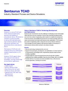
special objects Figure 2: Binary PIF data primitives independent. Adopting the PAI to another operating system is an easy and straightforward task. On top of the system layer, a file layer deals with physical files and objects. The compressing and caching layers take the necessary performance and space aspects into account. The basic layer handles the structure of the information stored in the PIF (it only deals with primitive data as can be seen in Fig. 2), whereas the interface layer allowes access to PIF objects, suited for advanced C. Both layers are constructed with automatic code generators, thus enabling an easy adoption to future changes. The interface layer is the standardized interface to the PIF data base on which all programs which handle PIF files should be set up. To allow easy data access, an application layer has been designed. It deals with whole PIF objects - like pointLists, lineLists, Grids (see Fig. 3) -, whereas the interface layer only supports "smaller parts" -e.g. nameLists, valueLists - o f these objects. The application layer provides useful functions like unit conversion, scaling and transformation. It is not restricted to C; it is also interfaced to FORTRAN and LISP applications. Common applications can easily use data stored in PIF format by only calling the functions (for C, subroutines for FORTRAN) of the application layer. It shall be pointed out that an extension of the application layer is possible and very simple. The interface layer will then serve as a standardized interface to the PIF data base.
481
User Interface Agent with PIF Editor (based on X11R4) Technology CAD Shell (based on LISP) TCAD PROMIS PDBM MM PAI application layer PAI interface layer PAI basic layer
PIF ASCII File
PAI compression layer PAI caching layer System layer
Figure 3: Binary PIF data primitives The integrated and self-consistent design of data exchange format syntax, application interface functionality and shell programming language offers many benefits both from the programm e r ' s and user's point of view and is considered a superior solution compared to stand-alone approaches of TCAD systems or data exchange formats.
5
Conclusion
T h e TCAD-oriented PIF, especially the application interface, has been proven as an expressive a n d powerful means in simulators like MINIMOS [5], PROMIS [6] or VLSICAP [7], and makes u p the base of our integrated technology CAD system [3]. Extensions will include a network layer and a message passing protocol based upon it, not only allowing applications to access remote binary PIF files on a database server, but enabling clients to communicate with each other through the interface, thus enforcing distributed processing concepts in systems to come.
482
Acknowledgement This project is supported by the research laboratories of: AUSTRIAN INDUSTRIES - AMS Int. at Unterpremstatten, Austria; DIGITAL E Q U I P M E N T Corp. at Hudson, USA; SIEMENS Corp. at Munich, FRG; and SONY Corp. at Atsugi, Japan.
References [1] S. Duvall, An Interchange Format for Process and Device Simulation, on Computer Aided Design, Vol. 7, pp. 489-500, 1988.
IEEE Transactions
[2] A. Wong et al, The Intertool Profile Interchange Format, Proc. NUPAD III, pp. 61-62,1990 [3] S. Selberherr et al., The Viennese and Device Modeling, Oiso, 1991
TCAD System,
Proc. Int. Workshop on VLSI Process
[4] F. Fasching et al., An Integrated Technology CAD Environment, Technology, Systems and Applications, Taipei, Taiwan, 1991.
Proc. Int. Symp. on VLSI
[5] S. Selberherr, Three Dimensional Device Modeling with MINIMOS 5, Proc. International Workshop on VLSI Process and Device Modeling , pp. 40-41, 1989. [6] G. Hobler et al, RTA-Simulation m , pp. 13-14, 1990. [7] F. Straker et al., Capacitance 602-608, 1986.
with the 2D Process Simulator
Computation
for VLSI Structures,
PROMIS,
Proc. NUPAD
Proc. EUROCON, p p .