2(10), 2010, 5058-5068 .... Control Studio (IPCS) [Ngalamou and Myers (2006, 2010). .... results in a normalized database that is required for more efficient data access. ... Update, save, delete and query can be considered the child classes, ...
Lucien Ngalamou et al. / International Journal of Engineering Science and Technology Vol. 2(10), 2010, 5058-5068
A PLC DATABASE – A SELECTION ENGINE FOR EFFECTIVE DEPLOYMENT OF PLC’S LUCIEN NGALAMOU School of Engineering, Grand Valley State University 301 W. Fulton Street, Grand Rapids, MI 49508, USA LEARY MYERS Department of Physics and Engineering, University of the West Indies Mona Campus, Kingston 7, Jamaica
Abstract: This paper presents the design considerations of a programmable logic controller (PLC) Database, which can be used for effective selection of PLCs and embedded microcomputers for process control and automation. It is a component of a software tool called Industrial Process Control Studio (IPCS) dedicated to industrial process control and automation. IPCS is organized in four major modules according to the criteria of modeling, supervision, humanmachine interfacing, and virtual representation. Keywords: PLC Database; Effective Selection; Industrial Process Control Studio. 1. Introduction Industrial processes have resulted in the widespread manufacture of items which are used by many persons on a daily basis. These items include appliances, vehicles and even medical drugs. These processes are a fixed known sequence of steps which the manufacturer of these items follow in order to produce an item of the same quality, repeatedly. The automation of these processes involves the use of devices such as programmable logic controllers and embedded microcontrollers. These devices use parameters such as temperature and pressure in a chemical industrial process, for example to help regulate the process. A programmable logic controller (PLC) can be defined as a digital computer used for automation of industrial processes, such as control machinery on factory assembly lines [ Warnock (1998)], while an embedded microcontroller can be defined as a general-purpose microcontroller based system provided by many semiconductor manufacturers for rapid prototyping purposes [ICE (1993)]. The use of these devices gives rise to a problem which is the decision of choosing the most efficient PLCs or embedded microcontrollers for a particular industrial process. This therefore motivates the need for a decision making tool to help engineers, technicians and small companies who are involved in these industrial processes to choose the appropriate PLC or embedded microcontroller for the job. This decision making tool can be in the form of a database which would provide reference for existing PLCs and embedded microcontrollers on today’s market. Engineers and technicians, once furnished with the requirements for a controls process, can then use these requirements to search the database which would be populated with PLCs and embedded microcontrollers to find the device that best suits their needs. A database can simply be defined as a collection of interrelated data [Silberschatz et al. (1997)]. This collection of data can be stored on physical material such as paper or where the data is stored in electronic format it is accessible through the use of computers. This interrelated data is organized and used in such a way that it increases the knowledge of the persons who use it. In today’s world, databases are in widespread use and its list of users includes banks, hospitals, universities and utility companies just to name a few. For example, utility companies use databases to keep track of their customers and their utility records.
ISSN: 0975-5462
5058
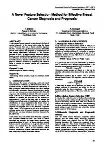
Lucien Ngalamou et al. / International Journal of Engineering Science and Technology Vol. 2(10), 2010, 5058-5068 The tool presented in this paper called ”PLC Database”, involves developing a database which can help persons and companies who work with these devices to choose the suitable PLC or embedded microcontroller for a particular industrial control process. Also, a database is to be developed as a module for a software tool called the Industrial Process Control Studio (IPCS) [Ngalamou and Myers (2006)]. It might be interesting to consider that a PLC or any other device to be used in a control process as a resource, and it is when the control problem is clearly modeled that a choice of PLC is made. Reasoning alone this line, a research project [Ngalamou and Myers (2006, 2010)] was initiated that consists of analyzing and developing an industrial process control tool for efficient deployment of PLCs in single or distributed modes. In this context, deployment means all the steps that consist of control specification, model capture of the process using IEC programming languages, formal verification, resource allocation, virtual plant modeling, supervisory control, and code generation. Process Automation may be conceptualized in terms of above functional modules. Each of these modules is responsible for the execution of some particular program functionality, and collectively, they function as the Industrial Control Studio. Figure 1 below is a block diagram of the Industrial Process Control Studio, and actually serves as a template for the implementation of the control studio software tool.
Fig. 1. Block Diagram of the Industrial Control Studio Tool
It is to be noted all the modules provided for the control studio consist of the following: - Visual Plant Generator - Formal Verification - Schematic Generator Resource Allocation and Database - Simulator and Real-time Debugger - Report Generator - Retargetable Code Generator - IEC 61131-3 Model Capture - Scada Module* *
Supervisory Control and Data Acquisition
ISSN: 0975-5462
5059
Lucien Ngalamou et al. / International Journal of Engineering Science and Technology Vol. 2(10), 2010, 5058-5068 - Human-machine Interface (HMI) - XML Engine and Synchronizer. These modules are further organized in four major groups according to the criteria of modeling, supervision, human machine interfacing, and virtual representation. The remainder of this paper is organized in four sections. Section 2 describes the design concept and implementation of the PLC Database followed by section 3, which presents the testing. A conclusion is presented in section 4. 2. PLC Database Development A database can be defined in various ways. According to [Silberschatz et al. (1997), Date (2000)], it is the collection of data that contains information about a single enterprise. It can be also be seen as a collection of files. However, it is possible to adapt a definition that is consistent with the database presented in this paper. That is, the database refers to the physical files that store the data. These files are also data files as noted in [Date (2000)]. A database is required to provide reference for existing PLCs and embedded controllers on the market. This database would have to take into consideration the intended requirements of the design and the various constraints placed upon the different PLC configurations.
2.1. Database Requirements This design entitled ”PLC Database” involves developing a database which can help engineers and companies who work with these devices to choose the suitable PLC or embedded microcontroller for a particular industrial control process. In addition, the database is to be developed as a module for a software tool called the Industrial Process Control Studio (IPCS) [Ngalamou and Myers (2006, 2010). The IPCS is a tool dedicated to industrial process control and automation. Therefore the scope of the design is to create a database which is meant to be a reference of existing PLCs and embedded microcontrollers on today’s market and additionally as a module for the IPCS. Necessary information from the analysis of data sheets should also be captured and represented in the database as these provide essential parameters for PLCs and embedded controllers. These variables provide a base from which we are able to adequately make a calculated selection of the most suitable PLC for the intended configuration. Alternatively a user may desire to search the database for embedded controllers that satisfy his specification such as the size of the address or data bus, the clock speed, the size of the memory, the number of input/output ports, and execution speed. The database has the ability to generate reports, thus demonstrating or offering further detailed information on the design concerning the choice of particular PLC or embedded controller. 2.2. Database Specification The specification is a corollary of the requirements of the database. A data model† must be decided in order to proceed in specifying the database. The resultant conceptual design of the data model represents the conceptual schema of the real-world domain being modeled. It consists of all the entity sets, relationships and constraints that should reflect all the enterprise requirements on the database. We will use the Entity-Relationship (E-R) data model that will be depicted using the E-R Diagram. The E-R diagram is usually expressed differently in academia than in an enterprise. There are various tools‡ that can be used to create E-R diagrams that each provides a different look and feel to these diagrams that are used widely in the database industry. These tools, which fall under the computer aided software engineering (CASE) category, also incorporate various beneficial functionalities like specification capabilities, design capabilities, code generation for particular databases form the E-R diagram and so on and they have their particular conventions as to what the symbols represented in the E-R diagram means. The E-R diagram for the specified database was created in a tool called DeZign [DeZign Tool (2010)] for Databases and is displayed in Figure 2 below.
† A data model provides a framework in which to specify what the requirements of the database users are, and how the database will be designed to fulfill these requirements ‡ Such tools include DeZin, Case Studio, Embacadero ER Studio, etc.
ISSN: 0975-5462
5060
Lucien Ngalamou et al. / International Journal of Engineering Science and Technology Vol. 2(10), 2010, 5058-5068
Fig. 2. Entity relationship diagram for PLC Database (showing attributes)
The E-R diagram shows the entities and the relationships between them and it encapsulates the following business rules: 1) The relationship between the CPU NAMES and PLC CPU tables establishes the constraint that a particular CPU can be associated with one or more PLC or one or more SUPPORT entities. That is, a particular PLC or supporting PC may exist with different types of processors. This is from the perspective of the CPU. 2) The relationship between the OS NAMES and PLC OS tables establishes the constraint that a particular PLC or supporting PC can be associated with one or more OS. This relationship demonstrates this from the perspective of the OS.
ISSN: 0975-5462
5061
Lucien Ngalamou et al. / International Journal of Engineering Science and Technology Vol. 2(10), 2010, 5058-5068 3) The relationship between the PLC NAMES, ACCESSORIES and MICROCONTROLLER§ tables establishes the constraint that a particular PLC or microcontroller configuration may require zero or more accessories in order to be completely functional. These accessories include things like batteries, memory cassettes, connecting cables etc. 4) The relationship between the PLC NAMES and EXPANSION MODULES tables establishes the constraint that a PLC may exists with zero or more expansion input/output modules depending on the type of PLC. 5) The relationship between the PLC NAMES and PLC AC INPUT tables establishes the constraint that a PLC may take an AC input. 6) The relationship between the PLC NAMES and PLC DC INPUT tables establishes the constraint that a PLC may take a DC input. 7) The relationship between the PLC NAMES and PLC ANALOG INPUT tables establishes the constraint that a PLC may take an analog input. 8) The relationship between the PLC NAMES and PLC RELAY OUTPUT tables documents the specification for the PLC’s relay output if one exists. 9) The relationship between the PLC NAMES and PLC TRANSISTOR OUTPUT tables documents the specification for the PLC’s transistor output if one exists. 10) The relationship between the PLC NAMES table and PLC TRIAC OUTPUT tables signifies the fact that a PLC can have a triac output. 11) The relationship between the PLC NAMES and PLC CPU tables establishes the constraint that a PLC can exist with different CPUs. This is similar to constraint (a) above but from the perspective of the PLC. 12) The relationship between the PLC NAMES and PLC OS tables establishes the constraint that a particular PLC can exist with different OSs. This is similar to constraint (b) above but from the perspective of the PLC. 13) The relationship between the PLC NAMES and NETWORK OPTIONS tables indicates that a PLC can have zero or more network options associated with it. 14) The relationship between the PLC NAMES and PLC TIMERS tables indicates that a PLC can have zero or more times associated with it. 15) The relationship between the PLC NAMES and PLC COUNTERS table indicates that a PLC can have zero or more counters associated with it. 16) The relationship between the SUPPORT and PLC CPU tables indicates that a supporting PC can exist with one or more CPUs. This is similar to (1) from the perspective of the supporting PC. 17) The relationship between the SUPPORT and PLC OS tables indicates that a supporting PC can exist with one or more OSs. This is similar to (2) above but from the perspective of the supporting PC. 18) The relationship between the PLC NAMES and SUPPORT tables enables each PLC to have zero or more supporting PC hardware and also allows a supporting hardware to be associated with zero or more PLCs.
§
Microcontroller and embedded controller have the same meaning
ISSN: 0975-5462
5062
Lucien Ngalamou et al. / International Journal of Engineering Science and Technology Vol. 2(10), 2010, 5058-5068 19) The relationship between the MICROCONTROLLER and MICROCONTROLLER MODULES tables indicates that a microcontroller will have one or more microcontroller expansion boards associated with it. 20) The relationship between the CODE REFERENCE table and the other indicated tables signifies that each type of code in the reference table must be unique and each of the other tables accesses this information.
2.3. Construction of the Data Structures Entities**, relationships†† and their attributes‡‡ need to be determined from the requirements that were given for the database. The distinction between an attribute and an entity set is dependent on the structure of the real world enterprise being modeled and on the semantics associated with the attribute in question [Silberschatz et al. (1997)]. Also the idea of distinguishing an entity set or a relationship set was evaluated by choosing the design that would minimize storage space and reduce redundancy in the database. Reducing the replication of data to a minimum is a good database design practice that lessens the potential of inconsistencies in the database after updates. This results in a normalized database that is required for more efficient data access. Entities, relationships and accompanying attributes that are required for the creation of the database were derived from the analysis of the data sheets for the PLCs and microcontrollers. The detailed arrangement of the specifications on the datasheets offered a very rich source of information especially for attributes. Tables are analyzed and arranged in a manner that would most suitably represent the data in the database. Tables are not only created to represent the characteristics or properties of PLCs and embedded controllers but also for the support software and accessories that may be required in constructing a system. Every effort was made to reduce redundancy and conserve on physical storage while improving performance by presenting a reasonably normalized database. A conceptual view of the database can be seen in Figure 3 below.
Fig. 3. The conceptual view of Database [Gordon (2006)]
PLCSCHEMA is the only schema that owns tables. For each of these tables a public synonym of the same name is created. The PLC USER ROLE object is created to be used to administer a set of privileges on the tables owned by **
An entity id a “thing” or “object” in the real world that is distinguishable from all other objects.
††
A relationship is an association among two or more entities An attribute is a descriptive property possessed by each member of an entity set
‡‡
ISSN: 0975-5462
5063
Lucien Ngalamou et al. / International Journal of Engineering Science and Technology Vol. 2(10), 2010, 5058-5068 PLCSCHEMA. The object privileges SELECT, INSERT and UPDATE, along with the CONNECT privilege are granted to the PLC USER ROLE object. This role is then granted to the PLC USER1 database user object, which essentially give it access to the tables of the PLCSCHEMA through the existing synonyms. Hence security is managed through the PLC USER ROLE and users that are granted this role will not be able to alter or delete from the tables. The actual designs for the database, class and GUI were implemented using them both and then they were integrated using Qt built-in SQL Class [Qt Tool (2010)] in addition to the class which was created specifically for integrating the database with the GUI. It is noted that this class can be used to integrate the database with other GUIs. The resulting product of this process can be called the PLC Database. Additionally, a user manual was generated so users of the PLC Database can use it to get help and importantly, how to interface the database module with other applications or GUIs that the IPCS may use.
2.4. Class Design The database must be able to interface with any C++ base application or graphical user interface. The solution is a class which can be used by any GUI to use components which will allow the user to perform operations on the database. This concept is depicted in the diagram shown in Figures 4 and 5.
Fig. 4. The conceptual view of the Database
ISSN: 0975-5462
5064
Lucien Ngalamou et al. / International Journal of Engineering Science and Technology Vol. 2(10), 2010, 5058-5068
Fig. 5. UML Class Diagram of the System
From the database design, it can be seen that the information about PLCs and embedded microcontrollers are spread across tables. Each table stores a particular set of information about the PLC or embedded microcontroller. Therefore, the class will contain functions which will allow users of these functions to perform the operations stated before on the tables. Based on the operations, the following class hierarchy diagram shown in Figure 6 was developed.
Fig. 6. IPCS Integration hierarchy
Update, save, delete and query can be considered the child classes, whereas IPCS integration class is the parent class. This means that the IPCS integration class combines the functions and methods contained in the child classes. The update child class will contain the methods for updating the tables. The save child class will contain methods for saving to the tables and the delete child class will contain methods for deleting from the tables. The query child class will contain the methods for querying data from the tables. When an object is created from the IPCS integration class, it will be able to use the methods from all the classes which make up the IPCS integration class i.e. update, save and delete. This means that functions which need to interact with the database need to create an object of the IPCS integration class in order to perform operations on the database. The GUI can therefore use this concept to allow the user to interact with the database. 2.5. Program Architecture The architecture of the system decides how the system capabilities are associated with the requirements specification. The architecture which would be used is the implicit invocation style. Implicit invocation allows the system to perform functions based on events which occurs. These events can be events such as command buttons being pressed, the mouse being clicked, windows losing focus, keyboard presses and menu selection. Implicit
ISSN: 0975-5462
5065
Lucien Ngalamou et al. / International Journal of Engineering Science and Technology Vol. 2(10), 2010, 5058-5068 invocation is chosen because it is an architecture which is used to respond to events such as those mentioned before which occur frequently in a GUI system. In addition, certain modules or components can be reused in later programs or extra functionality can be added in later revisions of the system. Modules can also be registered for multiple events. Since GUIs are very interactive i.e. the user uses the mouse and keyboard frequently, the nature of the eventdriven concept which implicit invocation is based on becomes an advantage since the events are only triggered by the user. This means an event which the user causes can be assigned to a particular module which will facilitate the user's reason for causing the event. Figure 7 attempts to depict this concept.
Fig. 7. Implicit Invocation applied to the system
3. Testing Testing involved checking the system for errors, faults and to learn if the requirements specified in the SRS§§ [SDLC (2010)] were met. Unit testing and integration testing were done to locate any errors or faults in the system. Unit testing involved using black box testing on the components of the system. Test cases were developed to test every component of the system. These test cases included the input of normal, abnormal and extreme data where it was applicable. The result of unit testing revealed no known faults in the system. Integration testing involved testing of the system when the components were put together to form the overall system. The Big-Bang approach was chosen because of the hierarchy of the system consisting of two levels. Integration testing revealed no known faults in the system. Functional testing involved checking to see if the functional requirements specified in the SRS were met. The result of this phase of testing revealed all the functional requirements were met. Performance testing involved §§
Software Requirements Specification
ISSN: 0975-5462
5066
Lucien Ngalamou et al. / International Journal of Engineering Science and Technology Vol. 2(10), 2010, 5058-5068 checking to see if the non-functional requirements specified in the SRS were met. The result of this phase of testing revealed that the non-functional requirements were met. Further testing would have involved acceptance and installation testing but due to time constraints these phases of testing were not completed. Overall, testing revealed no known faults with the system and the requirements specified in the SRS were met. The user can therefore add, update and delete PLC and embedded microcontroller records without the fear that the system would fail. In terms of component hierarchy, the system consists of two levels i.e. the GUI which is the higher level and then all the other defined components which is the lower level. In this lower level, the components can be considered separate independent entities. Consider the hierarchy diagram shown in Figure 8.
Fig. 8. Component Hierarchy
There are a number of integration testing approaches which are available and were talked about in the foundations section but the one which is most suited to this system is Big-Bang integration testing. The other approaches would have required that the system had a hierarchy system containing of more than two levels, whereas the Big-Bang approach involves testing all the components individually and then testing the entire system to see if it corresponds the design requirements. The unit testing phase has dealt with testing the individual components so all that needs to be done is to test the entire system to see if it satisfies the design requirements. In the design, specifically the system design of GUI, the design requirements for how the user will interact with the system is specified. Most of these requirements involve the user selecting options on the GUI. Test cases will therefore be developed to test how the GUI and the other components are used to realize the system and fulfill those requirements. The function testing was carried out to ensure that the integrated system performs its functions as specified in the requirements. The following figure shows the PLC database in one of its different modes of operation and configuration.
ISSN: 0975-5462
5067
Lucien Ngalamou et al. / International Journal of Engineering Science and Technology Vol. 2(10), 2010, 5058-5068
Fig. 9. Configuration for New Record
4. Conclusion The design of a functional database system called the PLC Database was developed using the relational data model. The tool has the following features: - The users of the PLC Database can successfully add, update, delete and query, PLC and embedded microcontroller records. A graphical user interface was created using Qt Tool and can be used to interact with and validate inputs to the database. - The database can be used as a module for the Industrial Process Control Studio. Although the PLC Database was designed to be integrated into IPCS, it can also be used by consultant engineers as well as machine manufacturers. References [1] [2] [3]
Date C. (2000), An Introduction to Database Systems, Addison- Wesley, 2000. DeZign Tool (2007), http://www.datanamic.com/dezign/index.html, consulted in October 2010. Gordon, A. (2006), Automatic Resource Allocation and Model Verification in Programmable Logic Controllers, Master Computer Science Thesis, University of the West Indies, Mona, Jamaica, 2006. [4] ICE (International Electrotechnical Commission) (1993), IEC Standard 61131-3: Programmable Controllers - Part 3, 1993 [5] Ngalamou, L. ; Myers, L., (2006), An Industrial Process Control Studio Development Tool: The IEC 61131-1 Model Capture Features, Proceedings of the SICE-ICASE, 2006. International Joint Conference Oct. 2006 Page(s):2874 - 2878. [6] Ngalamou, L. ; Myers, L. (2010), A Software Approach for the Design of a Virtual Plant Generator, Int. Journal of Computer Science and Network Security, Vol. 10 No. 9, September 2010, pp. 48-56 [7] Qt Too (2010), http://qt.nokia.com/, consulted in October 2010. [8] SDLC (Software Development Life Cycle) (2010), http://www.stylusinc.com/Common/Concerns/SoftwareDevtPhilosophy.php, consulted in October 2010 [9] A. Silberschatz,, A. ; Korth, H. F. (1997), Database System Concepts, Third Edition, McGraw Hill. [10] Warnock, I., Programmable Logic Controllers - Operation and application, Prentice Hall, Englewood Cliffs, NJ; 1998.
ISSN: 0975-5462
5068