In our implementation, we utilized Android Interface Definition Language (AIDL) and Bound ...... and 512 MB memory, and run Android 2.2. 6.2 Occurrences of ...
JOURNAL OF INFORMATION SCIENCE AND ENGINEERING 29, 1171-1194 (2013)
A Practical Framework for Self-Stabilization in Service-based Mobile Ecosystem* JAE YOO LEE, HYUN JUNG LA+ AND SOO DONG KIM Department of Computer Science Soongsil University Dongjak-Ku, Seoul, 156-743 Korea Mobile devices are widely accepted as a convergence machine, which provides both cell phone capability and a lightweight computing capability. However, mobile devices have a major drawback of limited computing power and resources such as main memory and battery life. Service-based mobile applications are emerged as an efficient solution to overcome this limitation of mobile devices. On the other hand, with the advent of more powerful mobile devices, mobile devices are actively participating as computer nodes and performing enterprise functionality. In this paper, we present a practical framework for dynamically deploying services. With the ever increasing computing power of mobile devices, we project that mobile devices can also be used as computer nodes deploying services. A number of benefits for deploying services on mobile devices existed. In this paper, we define an ecosystem for service-based mobile computing, and present techniques for dynamically deploying services on station nodes and mobile nodes, which are challenging problems. By applying dynamical deployment of services on both station and mobile nodes, the overall quality of the ecosystem can be consistently maintained. Keywords: services, mobile computing, migration, replication, self-stabilization
1. INTRODUCTION Mobile devices are accepted as a convenient convergence machine which provides both cell phone capability and computing capability. However, they have limited computing power and resources [1, 2]. Consequently, complex applications consuming a large amount of resource could not be deployed on them. To overcome the limitation, service-based mobile computing is emerging [3-5]. In this computing model, services deployed on server sides are invoked by client applications, yielding a number of benefits over standalone mobile apps [4]. However, in enabling service-based enterprise mobile computing, there is a compelling challenge, lack of stability and performance. In service-oriented computing, services can be instable and reveal low performance due to unexpected high volume of service invocations, degradation of network bandwidth, and faults on services. It becomes even evident with mobile computing since the network bandwidth available on mobile devices such as 3G is considerably low. To remedy these problems, we present a new eco-system for service-based mobile computing, called Service-based Mobile Ecosystem (SME). Especially, we present a process of managing stability of services of SME in autonomous Received December 4, 2011; revised April 4, June 4 & July 18, 2012; accepted August 16, 2012. Communicated by Jiann-Liang Chen. * This research was supported by Basic Science Research Program through the National Research Foundation of Korea (NRF) funded by the Ministry of Education, Science and Technology (2012R1A1B3004130, 2012R1A6A3A01018389). + Corresponding author.
1171
1172
JAE YOO LEE, HYUN JUNG LA AND SOO DONG KIM
manner. If SME can dynamically measure its overall quality, identify faulty services, and apply service migrations and replications in autonomous manner, the quality of the ecosystem can be consistently maintained, i.e. the stability of SME is maintained. The two key elements of the self-management process are Quality Model with metrics to measure the overall quality of SME and techniques for Dynamic Service Deployment. An innovation attempted in our research is to utilize ever-increasing computing power of mobile devices in providing stable quality of services. That is, we devise a new computing model where mobile devices are utilized as both client devices and servers deploying cloud services. Here, the dynamic remedy techniques are based on the assumption that each service is a highly cohesive functional unit, and hence independently deployable and be invoked. This is the component-as-a-service (CaaS) type in cloud computing [6]. Other types of services such as software-as-a-service (SaaS), platformas-a-service (PaaS), and infrastructure-as-a-service (IaaS) is not feasible for dynamic deployment. Beyond the cloud services, another aspect of the ‘service’ is that any functional component which is designed to be reused, provides public interfaces, and executes on the behalf of service invokers can be a service. Currently available middleware products and frameworks for cloud computing do not provide effective and practical schemes for autonomous manageability of services and dynamic service deployment. Especially, dynamically deploying services on mobile devices is not considered with current approaches and products. In this paper, we present a practical framework for self-managed stability of services for mobile computing. In section 2, we summarize related work, and section 3 present the new model for self-stabilizing service-based mobile computing environment, SME. Section 4 is to present the process for applying autonomous stability management in SME and its instructions. Section 5 presents methods to dynamically deploy services on station nodes and mobile nodes respectively. Section 6 presents the result of our experiment for applying SME.
2. RELATED WORKS A mobile agent is a composition of software and data which is able to migrate from one node to another autonomously and continue its execution on the destination node [7]. Mobile agents, therefore, can be treated as a unit of services on the cloud computing environment. But, due to the characteristics of mobile agent such as Autonomy, Personality, High Performance and Fault-tolerance [8], mobile agents are slightly different from cloud services. Mobile agents are mainly targeted for applications distributed over wide area network (WAN) with low bandwidth and high latency because they reduce network load, overcome network latency, execute autonomously, and adapt dynamically [9]. By applying the mobile agent to cloud computing, the cloud services can be migrated in a cloud or over the inter-clouds. Therefore, services with mobile agent can effectively handle quality of the services through reducing network loads. Chen and his colleagues proposes a mobile agent-based service for cloud computing system with high scalability, named Service as an Agent Service (SaaAS) [10]. SaaAS is a unit of mobile agent which includes data, software, and common runtime libraries to provide its functionality to users with high performance. However, their work only fo-
FRAMEWORK FOR SERVICE-BASED MOBILE ECOSYSTEM
1173
cuses on the service migration among the typical station. Moreover, their SaaAS is too heavy to be migrated dynamically because the SaaAS contains data, software, and even runtime libraries. Since cloud services provide complete functionalities to users and the services are not small enough to migrate its functionality with relevant data and runtime environment. It can cause another network overhead increasing communication cost. Haas’s work presents an autonomic approach to network service deployment that scales to large complex network [11]. The approach uses two-phase mechanism for efficient and flexible service deployment; global-level and local-level. Konstantinos’s approach proposes service migration to resolve the service placement problem in large scale and dynamic networking environments [12]. With migration, the cost of service provision is reduced and service facility reaches the optimal location. Nuno’s work presents a component-based framework for mobile agents supporting dynamic reconfiguration. Components can be added, removed and reconfigured at run time, with minimal disruption to the application [13]. It allows building highly adaptable mobile agent platforms. The proposed framework is targeted on JavaBeans components. Current works mainly focus on mechanisms of deploying services dynamically, and do not consider key issues addresses in our work including measuring quality of service ecosystem as whole, applying stabilization actions with service migration and replication, and deploying services even on mobile devices.
3. SERVICE-BASED MOBILE COMPUTING Mobile computing with subscription to services is emerging, however, the consensus on its underlying architecture and computing model is not yet reached. Hence, we propose a model for self-stabilizing SME. It is a computing environment where services and mobile applications are continuously operated, monitored, and managed to maintain normal states in autonomous manner. SME consists of several key elements as shown in Fig. 1; Service, Station Node, Mobile Node, Mobile Application, SME manager, and SME repository. MNode1
SNode2
App1
MNode2 App3
S91 S23
App2
S25 SME Agent
SME Agent
SME Agent
S61
S11 S24
SNode1
SME Manager SME Repository
SME Agent
SME Agent
S21
S62 S92
S12
S22
SNode3
Fig. 1. Key elements of SME.
Service is a reusable unit that provides cohesive functionality to service consumers. We distinguish types of services from instances of a service type. This is because a num-
1174
JAE YOO LEE, HYUN JUNG LA AND SOO DONG KIM
ber of service instances can be created from one type of service, and deployed on possible different server nodes. Note that SME is not intended to address SaaS, PaaS, and IaaS types of services. Dynamic migration of such services is not feasible due to their functional granularity; hence, SME is to provide dynamic migration and replication of CaaS type of services and other relative small-grained cohesive services. Let Ti be a type of a p service, from which a number of service instances can be created. And, let Si be a service instance of the service type, Ti. That is, for a service type Ti, its service instances are n Si1, Si2, Si3, …, Si . A node indicates a computer where services and applications are deployed. We consider two types of nodes; Station Node for conventional servers, and Mobile Node for a mobile device deploying services as well as applications. SNodei denotes a station node, and MNodei denotes a mobile device which deploys mobile applications and services. Mobile Applications are deployed on MNodej, and they subscribe services. Appi denotes a mobile application. One of the key features of SME is the capability of self-stabilizing its ecosystem [14]. SME Manager plays the role of coordinating all the activities in SME by initiating the actions of monitoring the overall QoS, making a quality remedy plan, and executing the plan in autonomous way. SME Agent is a software agent which monitors applications, services, and service invocations in background. And, the agent communicates with SME manager for transmitting QoS data and receiving dynamic remedy requests. Hence, background-running SME agents still have to be responsive by getting sufficient attention of processors. Deploying SME agent on station nodes such as Windows-based node is relatively trivial. This is the because that operating systems such as Windows, Mac OS, and Linux, provide efficient multi-tasking and scheduling schemes, partly due to their underlying resource-rich hardware platforms. However, implementing SME agents on mobile devices reveals technical difficulties, due to the limited resources. Moreover, the multitasking capability and efficiency of mobile platforms are not as much efficient as operating systems for desktop computer systems. For instance, SME agents are implemented as the unit of ‘service’ in Android, where Android assigns higher priorities for objects of ‘activity’ type and lower priorities for objects of ‘service’ type. As the result, the SME agent on Android platform could suffer from effective communications with the SME manager in case of resource constraints. Implementing the SME agent as an ‘activity’ object in Android also reveals problems of high resource drains and being put in ‘sleep’ mode. In our implementation, we utilized Android Interface Definition Language (AIDL) and Bound Service to design efficient interactions between the SME agent and SME service components. Bound Service is utilized for binding SME service components to the agent. As the result, the background-running agent becomes efficiently communicative. The deployment of the agent is done manually by users like typical applications. However, users can set various parameters such as users’ preference and device-specific constraints through the user interface of the agent. Since the SME agent is designed to interact with running applications and services rather than end users, it has a simple user interface for setting the parameters. SME manager maintains SME repository which stores configuration information of various SME elements. After each application of autonomous management activity, the repository is updated with the new configuration.
FRAMEWORK FOR SERVICE-BASED MOBILE ECOSYSTEM
1175
4. THE PROCESS AND INSTRUCTIONS In this section, we define a process to manage stability of services in SME, and present work instructions for the steps in the process. To support self-stabilization feature and dynamism, our proposed process consists of five steps as shown in Fig. 2.
1
Measure Overall QoS of SME
2
Determine Necessity of Remedy Action
3
Plan Remedy Action
4
Run Remedy Plan
5
Change Configuration of SME
No Problems? Yes
Fig. 2. Process for managing stability.
The proposed process can be applied in two modes; continuous and discrete modes. With continuous mode, SME agents run in background on the nodes, monitor the services invocation, and send quality-related measures to SME. The benefit of continuous model is to maintain the stability in timely manner; however it could result in an excessive overhead on the ecosystem. With discrete model, SME manager and agents run the five-step process at a specified interval such as every 30 minutes or every hour. This mode yields less overhead on the ecosystem; however the quality degradation problem may not be remedied in timely manner. 4.1 Step 1 for Measuring Overall QoS of SME In order to maintain consistent level of quality, it is desired to define a number of quality attributes and its metrics. To take needed actions for self-stabilization, we need to measure the overall quality of SME. We consider four levels to measuring quality; QoS of Mobile Application in Invoking Services QoS of Service Instance QoS of Service Type QoS of the entire SME There have been used several quality models such as ISO/IEC 9126 [15] and Web Service Quality Model (WSQM) [16]. Those models include quality attributes such as response time, throughput, and availability, with metrics. The proposed SME works with all these quality attributes. To consider various quality attributes in our quality model, we generalize the quality model, not only focusing on a specific quality attribute. Since the main focus of this paper is not on presenting the quality model of SME
JAE YOO LEE, HYUN JUNG LA AND SOO DONG KIM
1176
but on presenting the overall process of self-stabilization with practical mechanisms, we show how SME incorporates with a generic quality model by using an instance of the generic quality model, which is about efficiency in terms of response time. Additional quality attributes can be accommodated in the similar way. 4.1.1 QoS of mobile application We first consider the QoS of a mobile application, Appi, in invoking service instance k k of a service type, Sj . The QoS for this invocation, QMobileApp(Appi, Sj ), can be differently measured, depending on a quality attribute. For example, when you consider efficiency in terms of response time (i.e. RT), QMobileApp(Appi, Sjk) can be measured as: if RTMobileApp ( Appi , S kj ) RTmax , 0 QMobileApp ( Appi , S kj ) RTMobileApp ( Appi , S kj ) else 1 RTmax
(1)
where RTMobileApp(Appi, Sjk) is the response time when Appi invokes Sjk, and RTmax is the maximum possible value of response time for any service invocations and is derived from a history log of service invocations. If the measured response time exceeds RTmax, then the efficiency is set to zero rather than a negative number. The value range of QFResponseTime is 0…1, and the higher value of it denotes the faster response for the service invocation from the mobile app. When you consider other quality attributes, you can utilize quality metrics introduced in ISO/IEC 9126 [15] and WSQM [16] in a similar way. 4.1.2 QoS of service instance Now, we compute the QoS of a service instance QServiceInstance(Sjk), which is the average value of the QoS for all invocations on the service instance Sjk during a time period for the cycle of running the process for stabilization. It is measured as; n
k
QServiceInstance S j
Q i 1
APP , S k
MobileApp
n
i
j
(2)
where n is the total number of invocations made on the service instance, Sjk, from applications, and APP(i) denotes the application which initiated the ith invocation on the service instance. The value of QServiceInstance( ) represents how degree of the QoS is guaranteed from the service instance during the time period. If its value is too low, the service instance becomes a potential target for service migration or replication. 4.1.3 QoS of service type By using the QoS measures on service instances, we compute the QoS of each service type, QServiceType(Sj). It is an average QoS of the service instances of the same service
FRAMEWORK FOR SERVICE-BASED MOBILE ECOSYSTEM
1177
type, and computed as; n
QServiceType ( S j )
Q
k ServiceInstance ( S j )
k 1
n
.
(3)
where n is the total number of service instances for a service type. The value of QServiceType( ) represents how degree of the QoS is guaranteed from the service type during the time period. If its value is too low, the service type becomes a potential target from which more service instances can be generated and deployed. 4.1.4 QoS of the entire SME
Now, we can compute the overall QoS of the entire SME by using QoS of all service types, QSME, and it is measured as; n
Q
ServiceType ( S j )
QSME
j 1
n
,
(4)
where n is the total number of service types in the ecosystem. The value of QSME represents how degree of the QoS is guaranteed on the service-based mobile ecosystem during the time period. That is, it is the indicator of efficiency for the entire ecosystem. 4.2 Step 2 for Determining Necessity of Remedy Action
To manage quality, it is common to define threshold values for quality attributes. If the value of a quality attributes drops below its threshold value, actions to remedy the quality problems are taken place. For SME, we define two threshold functions; Thresholdhigh(x) for the high-bound threshold value of x, which can be the ecosystem as a whole, i.e. SME, or a service type, Si. Thresholdlow(x) for the low-bound threshold value of x. To be practical, we assume that different service types may have different sets of two threshold values, Thresholdhigh(Si) and Thresholdlow(Sj). With the threshold functions, we define three possible states for a given element x; Normal state: The efficiency of x is in normal range, and hence no remedying action is required. Poor state: The efficiency of x drops below the Thresholdlow( ), and hence an action to remedy the low efficiency is expected. Exceeding state: The efficiency of x exceeds the Thresholdhigh( ), which probably indicates a waste of resources in delivering excessively high efficiency. An action to release some of the resource by removing some services instances.
1178
JAE YOO LEE, HYUN JUNG LA AND SOO DONG KIM
Thresholdlow(x)
Poor
Thresholdhigh(x)
Normal
• QoS is poor. • Needs remedy actions, s.a. migration and replication
Exceeding • Waste of resources • Consider ROI. • Reduce resource consumption.
Fig. 8. Three states of efficiency for SME elements.
It is essential to determine the right Thresholdhigh(Si) and Thresholdhigh(Sj). Since different services have different characteristics and are managed with different policies, it is challenging to determine threshold values of different services in a uniform way, and even more challenging to autonomously estimate these values. Therefore, service administrator’s intervention is required to set moderate threshold values for the service. As shown in Fig. 2, all the monitored QoS data is accumulated in the repository. From this accumulated QoS data, these values can be estimated without human administrator’s intervention. If there is no historical data, initial Thresholdhigh(Si) and Thresholdlow(Sj) are set by human administrators with their own knowledge. And, Thresholdhigh(Si) and Thresholdlow(Sj) are updated whenever any fault is detected. That is, whenever a poor state occurs, the value of Thresholdlow(Sj) is updated by computing the following formula: m
Thresholdlow (QServiceType ) ( QServiceType (S j ) / m j 1
where m is the total number of fault occurrences, i.e. poor state, and QServiceType(Sj) is the current service-level quality value when the fault occurs. Thresholdlow(QSME) is calculated as the same way as Thresholdlow(QSME). Thresholdhigh(Sj) is also updated whenever an exceeding occurs. The updating formula is the similar to one of Thresholdlow( ). The only difference is that Thresholdhigh(Sj) concerns the cases of exceeding state. The SME manager determines the necessity for taking remedy actions at two levels; Quality of Ecosystem (QoEco) level and Quality of Service (QoS) level. For QoEco-level determination, the efficiency of SME is compared to its threshold values, and the necessity of taking remedy actions is determined with following criteria; If QSME < Thresholdlow(SME), i.e. being in Poor state, an action to remedy the low efficiency of SME is to be planned and taken. This action is named to EnhanceQoS(SME). If QSME > Thresholdhigh(SME), i.e. being in Exceeding state, an action to release resources used by unnecessary service instances is to be planned and taken if the resource consumption presents any significant issue such as excessive cost. This action is named to ReclaimResource(SME). If QSME lies between two threshold values, i.e. being in Normal state, no action to manage services is expected. For QoS level determination, efficiencies of service types are compared to their threshold values, the necessity of taking remedy actions is determined with following criteria;
FRAMEWORK FOR SERVICE-BASED MOBILE ECOSYSTEM
1179
If QServiceType(Si) < Thresholdlow(Si), i.e. being in Poor state, an action to remedy the low efficiency of Si is to be planned and taken. This action is named to EnhanceQoS(Si). If QServiceType(Si) > Thresholdhigh(Si), i.e. being in Exceeding state, an action to release resources used by unnecessary service instances is to be planned and taken if the resource consumption presents any significant issue such as excessive cost. This action is named to ReclaimResource(Si). If QServiceType(Si) lies between two threshold values, i.e. being in Normal state, no action to manage services is expected. Hence, the result of applying step 2 can be any combination of the four types of service management actions; EnhanceQoS(SME), ReclaimResource(SME), EnhanceQoS(Si), and ReclaimResource(Si). Note that the resulting combination can be null. 4.3 Step 3 for Planning Remedy Action
This step is to devise plans for the management actions identified in step 2. The EnhanceQoS(SME) action is used for QoEco-level management, and its algorithm is given below; 1. 2. 3. 4. 5.
EnhanceQoS(SME) { Identify faulty service types, setOfFaultyServiceTypes. For each service type Si in the set, perform EnhanceQoSServiceType(Si); }
In line #2, a faulty service type is the one in poor state. In line #3, the action to enhance efficiency is applied to each service in the set of faulty service types, i.e. setOfFaultyServiceTypes. In line #4, an invocation to enhance efficiency at QoS-level is made, of which algorithm is given below. 6. EnhanceQoSServiceType(Si) { 7. Select faulty instances of Si, setOfFaultyServiceInstances. 8. For each instance Sij of the service type Si 9. Determine migration or replication. 10. Determine a target node, NodeID. 11. Invoke migrate( ) or replicate( ) with the parameters. 12. } At line #7, a faulty service instance is the one determined to be in poor state by using the threshold value, Thresholdlow(Si). This is because all instances of a same service type should be managed with the same threshold values. At line #8, either a migration or a replication is performed for each instance of the service type Si. Line #9 is to determine the type of action by using decision criteria. Table 1 shows some of the criteria. Identifying a complete list of the criteria can be a future research task.
1180
JAE YOO LEE, HYUN JUNG LA AND SOO DONG KIM
Table 1. Criteria for determining migration and replication. Situations Migration Replication EffServiceType(Si) is nearly zero. High Standard Deviation among Instances Low Standard Deviation among Instances If Sij is providing its functionalities to other customers j If Si is shared. If Sij is used exclusively for a client.
At line #9, the target node for migration or replication is determined by considering three criteria; whether an appropriate package is prepared in advance, whether node can ensure high quality, and how close the target node is to a problematic node. First, a type of candidate nodes is determined, which is either station nodes or mobile nodes. To migrate or replicate a service instance, service providers need to provide appropriate forms of service packages for different platforms in advance. By considering the kinds of service packages offered by service providers, SME can choose the right type of candidate nodes. That is, SME checks available package forms of the services, for example, ‘apk’ file for Android platform, and determine the type of candidates. Second, SME checks the current qualities of the nodes belonging to the type decided in the previous step. If a node holds sufficient amount of available resources in terms of CPU, memory, network, and so on, this is a good target node for running the services. Finally, among the nodes having enough resources, SME decides the nearest node to the node having a problematic service instance. To calculate this, we adopt shortest path algorithms such as Dijkstra’s algorithm [17]. The remedy plan generated by running the algorithm becomes a sequence of action scripts which are in two forms; Migrate(Sij, Node ID) which migrates the service instance to a target node designated by Node ID. Replicate(Si, Node ID) which creates a new instance of the service type Si and dynamically deploy the instance on a target node designated by Node ID. 4.4 Step 4 for Running Remedy Plan
In this step, SME manager carries out the remedy actions specified in a remedy plan. SME manager firstly identifies SME agents which deployed on the source node and the destination node. Then, SME manager prescribes to the SME agents what to do. After that, the SME agents operate their tasks Fig. 4, for example, depicts two cases for service migration and replication in a remedy plan. As shown in Fig. 4, service migration and replication are needed to remedy quality problems in SME. For service migration, a service instance Sij is to migrate from SNode1 to SNode2, and another service instance Sfh is to replicate from SNode3 to MNode1 for service replication. Therefore, SME manager firstly identifies those source nodes and destination nodes for service migration and replication, and notifies the information to
FRAMEWORK FOR SERVICE-BASED MOBILE ECOSYSTEM
SNode1
SNode2
SNode3
Sij
Sij
Sfh
SME Agent
SME Agent
SME Agent
1181
Sij
SME Manager SME Repository
SME Agent
Sfh+1
Sfh+1 App1
Service Migration Service Replication
MNode1
Fig. 4. Service migration and replication in a remedy plan.
the relevant SME agents respectively. Then, each SME agent prepares their task to assigned remedy action. For example, SME agent on SNode1 retrieves binary packages of the service instance Sij, and then the SME agent on the source node asks another SME agent on the destination node to operate service migration for the service instance Sij. After successfully migration the service instance Sij, the SME agent on the source node un-deploys the target service instance from the source node and removes the binary package file of the instance, then the SME agent finally notifies configuration changes to the SME manager. On the other hand, for service replication, SME agent operates same tasks except un-deploying and removing the target service instance from the source node. In case of service replication, the target service instance still remains on the source node, and hence the overall availability is also increased because two service instances operate same functionality to their consumers at the same time. 4.5 Step 5 for Changing SME Configuration
This step is to reflect the changes, from which applying the remedy actions, into the overall configuration of SME. By applying the self-stabilizing mechanism presented in our submission, quality of service instances which is a target of replication or migration is decreased. Therefore, individual customers who are subscribing the service have the penalty as slow response time. This is because the self-stabilizing mechanism also occupies certain amount of resources to be executed, and it has a negative impact on running the target service. Especially, in case of service migration, all of the processing sessions are stopped during the service migration, and those sessions are resumed after finishing the service migration process. It gives some delay to the customers, but the time duration for the service migration is relatively short. However, applying the self-stabilizing mechanism consequentially improves overall quality of the service type and SME.
5. DYNAMIC SERVICE DEPLOYMENT In this section, we present practical techniques to dynamically deploy services on mobile nodes as well as station nodes. To enable the proposed remedy actions as service migration and service replication, SME needs to provide techniques for transmitting a service from the source node to the destination node and for deploying the service on the
1182
JAE YOO LEE, HYUN JUNG LA AND SOO DONG KIM
destination node at runtime. For transmitting a service, both station and mobile nodes take the TCP/IP protocol. However, for dynamic service deployment, station and mobile nodes should take different ways to deploy the service at runtime because both nodes have different operating environments. Therefore, we describe the methods to dynamically deploy services on station nodes and mobile nodes respectively. 5.1 Dynamic Service Deployment on Station Nodes 5.1.1 Design
The cost for transmitting a service from a source node to a destination node is relatively large, and it can cause additional network overhead. Therefore, a method to reduce the transmission cost is required for higher efficiency. To enable this, we adopt an openclosed principle [18] to minimize service transmission cost. And we also utilize class loading mechanism to deploy a service at runtime on J2EE environment. Open-close principle is to close the common part and to open variable part for customization. Services in SME are transmittable with a support of stabilization methods, and SME agents deploy the services dynamically. Hence, we define five key elements to enable service dynamic deployment as shown in Fig. 5. «component» SME Agent
«component»
Transmittable Service
«abstract»
«WSDL»
Service Interface
Service Interface
Adaptor
Transmittable Services
Service Package
Realize Service Body
Communication Stubs
Fig. 5. Key elements for enabling service dynamic deployment.
Since SME agents and services interact with each other to perform dynamic service deployment, the elements are distributed into two participants. Abstract service interface, adaptor, and communication stubs are located in the SME agent and service interface and service body are located in the transmittable service. The elements in SME agent are not changed for the different types of services, i.e. common elements. They deploy various services on the station nodes by using class loading mechanism. On the other hand, the elements in the transmittable services are variable elements. That is, implementations of the elements depend on the types of services. The transmittable service is implemented with the same way of implementing conventional services, i.e. transparently. Service interface is an interface specification of a transmitted service in WSDL [19], and it describes endpoint address, binding information, operations, messages, and types of parameters for the service. Service body is a set of implementations to realize the service functionality. Service invocations from service consumers are operated within the service body. Since services are provided as a black-box form, such as binary Java class or WAR package, and common elements of the services are not needed to be transmitted,
FRAMEWORK FOR SERVICE-BASED MOBILE ECOSYSTEM
1183
SME transmits only the variable elements to reduce the transmitting cost. Abstract service interface is an interface exposed to the service consumers, which enables the service consumers to invoke dynamically deployed services. The interface is dynamically bound to the transmitted service interface. Adaptor is an intermediate object which inherits the abstract service interface and binds operations to an actual instance of a service body. To create an instance from the service body, the adaptor utilizes Class Loader APIs which are also available in Java and C++. The adaptor invokes the communication stubs to provide networking capability to the service. Communication stub provides networking capability for services deployed on the same station node. 5.1.2 Implementation
We now present our implementation of dynamic service deployment on station node. SME agent receives a request for deploying a service from SME manager, and the SME agent performs the actual deployment. Implementation of the manager and the SME agent largely depends on the runtime environment. Some application servers such as J2EE provide facilities for deploying services and components. However, there is no standard on the methods and its interfaces. Hence, we decide to avoid using these proprietary mechanisms. Rather, we utilize a class loading mechanism in Java since it is available on any Java-compliant environment. The SME agent defines an operation, transmitSVC(File svcPackage), that receives a package file which consists of a service interface and body of the service as shown in Fig. 5. The input parameter of the operation is a basic java object as a String object. However, actual data type which the SME agent receives is a stream data type, because the communication between two SME agents uses a socket protocol. Therefore, the SME agent converts the received data into a class file as shown in Table 2. Table 2. Implementation for converting data into class file. public void setClassFile(TransmittedSVC svc){ ... try { buffer = svc.BODY.read(); // Storing binary file into a buffer outFile = new DataOutputStream(new FileOutputStream("FILE Information for storing Class file")); // Making a Class file for dynamic 6 deployment 7 for (int i = 0; i < buffer.length; i++){ 8 outFile.write(buffer); 9 } 10 } catch (Exception e) { 11 // Exception handling 12 } }
1 2 3 4 5
At line #4, the SME agent reads a service body and stores it to a buffer when the SME agent received a service. The SME agent set a name of the class file in which the
JAE YOO LEE, HYUN JUNG LA AND SOO DONG KIM
1184
service is stored, at line #5. The name of class file is retrieved from the service interface. If the name of class file and the service name are different, a binding problem occurs. After converting the received data into a class file, the SME agent deploys the service which is received on the station node by using the class file. Table 3 shows a code segment of dynamic service deployment. Table 3. Implementation for initializing and running services. 1 private boolean deploySVCFromClass(){ 2 Object result = null; 3 try{ 4 // Creating a Class loader object 5 CustomClassLoader loader = new CustomClassLoader(); 6 // Loading a service class 7 Class clazz = loader.loadClass(svc.NAME); 8 // Instantiate a service instance 9 Object instance = clazz.newInstance(); 10 // Setting operations from service interface 11 Class[] svcOP = new Class[] {svc.INTERFACE}; 12 // Deploying service 13 clazz.deploy(instance, svcOP); 14 Return TRUE; 15 }catch(Exception e){ 16 // if service deployment is fail, then handle the exception 17 Return false; 18 } 19 }
The SME agent creates an instance of a class loader at line #5. By using the loader instance, the SME agent loads the service class file and creates an instance of the service at lines #7 and #9. The SME agent sets the service’s operations retrieving from the service instance at line #11. Finally, the SME agent binds the service instance and operations, and deploys the service on the node at line #13. By using the SME agent, a service can be dynamically deployed on new node without any human administrator’s work. 5.2 Dynamic Service Deployment on Mobile Nodes 5.2.1 Design
One of the noble features of SME is the ability to deploy services on mobile devices at runtime. Service-based mobile applications require network connection. Mobile devices tend to change an access point and be disconnected frequently [20], due to the mobility. And, it spends more time for responding the result from service due to the narrow network bandwidth. However, there are situations where services deployed on mobile devices can yield a better performance than conventional deployment of services on station nodes. For example, if a mobile node deploys a service and a number of service
FRAMEWORK FOR SERVICE-BASED MOBILE ECOSYSTEM
1185
consumers are placed in the same LAN area, invoking the service on the mobile node provides better performance than invoking the service deployed on the remote node. Deploying service needs more resource than running application because the services are used by other devices through the network [21]. Mobile nodes access to the Internet by using low speed connection, thus, reducing the load of service transmission is more important comparing to the station nodes. Therefore, we adapt open-closed principle to the mobile nodes just like dynamic service deployment on station nodes. Fig. 6 depicts a service structure for dynamic deployment on mobile devices.
Variable Element Common Element
Service Interface Realize
Service Loader
Service Body
Fig. 6. Common elements and variable elements of services on mobile nodes.
Service interface contains configuration information of the transmitted service, such as package name, service name, operations, messages, and parameter types. This information is used to load the right service on its memory. Service body is a set of implementations to realize functionality. Thus, service invocations from the service consumer are operated in the Service body. Service loader is the mechanism for dynamically deploying the service from the Service body. With the Service loader, new instance of the service is constructed and loaded on the memory. For example, in Android platform, each application is compiled and packaged in a single binary “apk” file that includes all of implementation classes in .dex files, resources, assets, and manifest file. Therefore, we come up with the idea to transmit services by using binary form, specifically “apk” file. The “apk” file contains all functions of the service, which is invoked by service consumers. Security issue is also considered here. That is, transmission of binary file from station node to mobile node will be implemented along with cryptography algorithms such as RSA and DES. After transmitting a service, the SME agent on the receiver side automatically deploy the service on the mobile devices by using the Service loader. In other words, the binary file will be automatically installed as an application on mobile nodes. 5.2.2 Implementation
We present our implementation of dynamic service deployment on mobile node. SME agent receives an “apk” file of the deployed service from another SME agent and performs the actual deployment. In our implementation, we utilize the class loading mechanism Android since it is available on any Android-compliant environment. After SME agent receives the “apk” file, it saves the file to the physical storage such as SD card and installs it. Table 4 shows a code segment of installing apk file. Firstly, we get the location of apk file on SD card at line #2. From line #4 to line #6, we call an activity with suitable intent to install that apk file at mobile node.
JAE YOO LEE, HYUN JUNG LA AND SOO DONG KIM
1186
1 2 3 4 5 6
Table 4. Implementation for Installing APK file. // Get location of apk file String fileName = Environment.getExternalStorageDirectory() + "/" + message.filename; // Start specific activity for install apk Intent intent1 = new Intent(Intent.ACTION_VIEW); intent1.setDataAndType(Uri.fromFile(new File(fileName)), "application/vnd.android.package-archive"); startActivity(intent1); Table 5. Implementation for Loading a Class in APK file.
1
Public DynamicLoader(Context context, String packageName, String classPath) { 2 // Load package 3 dalvik.system.PathClassLoader myClassLoader = new dalvik.system.PathClassLoader(getSourceDir(context, packageName), ClassLoader.getSystemClassLoader()); 4 try { 5 // Load class 6 handler = Class.forName(classPath, true, myClassLoader); 7 } catch (ClassNotFoundException e) { 8 e.printStackTrace(); 9 } 10 }
Table 5 shows a code segment for loading a class in “apk” file. At line #3, the method PathClassLoader of class devik.system gets the location of apk file in mobile device after installation. After getting the package path, we can now load the class object by calling method Class.forName at line #6. Table 6 shows an implementation for creating an instance of class. Table 6. Implementation for creating an instance. public Object newInstance(Object... args) { try { if (args != null) { // Make instance using constructor Constructor[] constructors = handler.getDeclaredConstructors(); for (Constructor constructor : constructors) { if (args.length = constructor.getParameterTypes().length) { Constructor con = handler.getDeclaredConstructor(constructor.getParameterTypes()); 10 return con.newInstance(args); 11 }
1 2 3 4 5 6 7 8 9
FRAMEWORK FOR SERVICE-BASED MOBILE ECOSYSTEM
12 13 14 15 16 17
1187
else // Make instance for default return handler.newInstance();
} return null; }
The new instance of class could be created by one of two ways, with constructor has parameters or constructor has no parameter. From line #8 to line #10, we check whether constructor has parameters or not. If yes, we use function getParameterTypes at line #9 to get the types of parameters and create a new instance at line #10. Otherwise, we call constructor with no parameter at line #14. Table 7 shows an implementation for invoke functions of class. Table 7. Implementation for invoking functions. 1 public Object invoke(Object aClass, String methodName, Object... args){ 2 try { 3 Class[] classes = null; 4 // Get parameters all methods 5 for(Method method:handler.getDeclaredMethods()) { 6 if(method.getName().equals(methodName)) 7 classes = method.getParameterTypes(); 8 } 9 Method m = handler.getDeclaredMethod(methodName, classes); 10 if(args != null) 11 // Returns the result of dynamically invoking this method. 12 return m.invoke(aClass, args); 13 else 14 return m.invoke(aClass); 15 } catch (Exception e) { 16 e.printStackTrace(); 17 } return null; 18 19 }
At line #5, we use a loop to find all of methods of the class. Afterwards, getParameterTypes function at line #7 is for getting the types of parameters in each method. At lines #12 and #14, invoke method invokes methods by one in two ways, methods which has parameters and which has no parameter.
6. EXPERIMENTS AND ASSESSMENT In this section, we present experiments with the proposed framework. The purpose of the experiments is to show that the remedy process of SME can successfully handle
1188
JAE YOO LEE, HYUN JUNG LA AND SOO DONG KIM
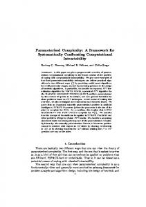
faulty services and maintain a consistent level of service qualities. 6.1 Experiment Setting and Scenarios
We implemented two services; S1 and S2. The service S1 provides network intensive functionality, whereas the service S2 provides computation intensive functionality. We have a server node which deploys the SME Manager and SME repository. In addition, we set up three station nodes with Windows platform and two mobile nodes with Android platform, as shown in Fig. 7. The SME agent is deployed on each node. We also implemented four Android applications which invoke the two services. The initial setup 1 for experiments is to deploy S1 on SNode1 and S21 on SNode2. The SME Manager is deployed on a server node along with SME Repository. The repository contains implementations of the two services, of which package sizes are 157 kb and 231 kb respectively. Both services have a response time of 1 second, i.e. RTmax is set to 1. The threshold values for the services are set to 0.4 for ThresholdLow and 0.9 for ThresholdHigh. Mobile applications are deployed on Google Nexus One devices, which have a 1 GHz processor and 512 MB memory, and run Android 2.2. 6.2 Occurrences of Quality Degradation
By using Poisson distribution [22], we generate service invocations for the two services, which result in faulty situations as shown in Fig. 8.
Fig. 7. Initial configuration of experimental environment.
FRAMEWORK FOR SERVICE-BASED MOBILE ECOSYSTEM
1
1189
Quality
ThresholdHigh
0.9 0.8
[192, 0.22] [219, 0.22] [176, 0.24] [286, 0.22] [117, 0.28]
[153, 0.32]
0.7
S21
[125, 0.4]
(285, 0.42) (176, 0.44) (114, 0.42)
0.6 0.5
(204, 0.4) (221, 0.39)
(153, 0.48) (121, 0.48) (257, 0.49)
0.4
[241, 0.5]
SME
(316, 0.48)
0.3 0.2 0.1
(392, 0.9)
S11
ThresholdLow
[103, 0.48]
SME
[117, 0.8]
S11
S21
0 …
52
53
54
55
…
176
177
178
QServiceInstance(S21)
QServiceInstance(S11)
179
QSME
180
… Time (seconds)
( ) Number of Service Invocations and Average Response Time for S11 [ ] Number of Service Invocations and Average Response Time for S21
Fig. 8. Occurrences of faulty situations of S11 and S21.
The x-axis indicates the elapsed time, and the y-axis indicates the quality of elements measured in efficiency. As shown in the figure, we observed two faults occurred mainly due to the congestions caused by extremely a high number of service invocations made in a short period of time. One fault occurred near the time period of 55 seconds 1 where the quality of S1 was dropped below Thresholdlow and consequently the overall quality, QSME, was dropped. During the time interval between 176 and 179 seconds, the quality measures of three elements showed a curve of degradation, but they are still above the thresholdlow. At the moment of reaching 180 seconds, a fault occurred. After that moment, tasks of devising a remedy plan and performing a service replication occurred, as described in section 6.4. 6.3 Applying Service Migration and the Result 1
The proposed process for remedying the fault on S1 recommends Service Migration using its algorithm, and the remedying process is shown in Fig. 9. Quality 1
ThresholdHigh
0.9 0.8 0.7
(0.32)
0.6 0.5
S21 SME S11
0.3
QSME ( )
0.2 0
QServiceInstance(S21)
ThresholdLow
0.4
0.1
QServiceInstance(S11)
Occurrence of Quality Problem
53
54
(0.9)
55
(0.99) (0.98)
Migrating Service
56 57 T1 = 1.8 s
Average Response Time For Service Instance S11
Performing Migrated Service
58 59 T2 = 1.5 s
60 Time (seconds)
Fig. 9. Effects of applying service migration.
JAE YOO LEE, HYUN JUNG LA AND SOO DONG KIM
1190
1
The QServiceInstance(S1) at 55 second is 0.1, which indicates the average response time 1 for S1 is 0.9 seconds according to the the metrics given in sections 4.1.1 and 4.1.2. By referring the remedy planning criteria, the SME manager determines Migration( ) as the remedy action. For running the selected remedy action, SME manager compares a cost to transmit the problematic service to the candidate nodes to select the most optimal target 1 node. With the experiment setting and the size of service package for S1, the service transmitting cost for SNode2 and SNode3 is same as 0.15ms. However, SNode3 has better amount of allocable resources than SNode2, because of existence of a deployed service. Thus, SNode3 is selected for the target node, and SME manager performs a function, Mi1 1 gration(S1, SNode3), to enhance the QServiceInstance(S1). By performing the service migra1 tion, the QServiceInstance(S1) is increased to 0.68, and consequently the QSME is also increased to 0.71. In the Fig. 9, T1 is a preparation time of performing the steps 2 and 3 in the management process, and T2 is an execution time of performing service migration. In this case, SME manager spent 1.8 seconds to make plan for remedy actions, and also spent 1 1.5 seconds to select a target node and migrate the service instance S1. Hence, the cost for running the service migration is the sum of T1 and T2. As shown in the figure, there is a proportional relationship between QSME and the remedy process. That is, QSME is largely affected by QServiceInstance and remedy actions taken on service instances. A lower QServiceInstance will lower QServiceType and eventually QSME. An effective remedy action taken on a faulty service instance will raise QServiceType and eventually QSME. Hence, a lower QServiceInstance decreases QSME, and the remedy process applied on service instances increases QSME. 6.4 Applying Service Replication and the Result
In this section, we describe a remedy action of service replication applied to a ser1 vice instance, S2 , which reveals the quality degradation problem as shown in the right side of the Fig. 8. By applying the remedy process, the SME manager diagnosed the problem and recommends a service replication for the case. Fig. 10 depicts effects of applying the remedy action. 1
Quality
ThresholdHigh
0.9 0.8
(0.26)
0.6 0.5 0.4
(0.5) (0.48)
ThresholdLow
0.3 0.2
(0.99) App4 Occurrence of Replicating Quality Problem Service
0.1 0 178
QMobileApp(App1, S11)
(0.28)
App4 App1 App2 App3
0.7
179
180
181
Performing Replicated Service
182
QMobileApp(App2, S21) QMobileApp(App3, S11) QMobileApp(App4, S21)
x
QMobileApp(App4, S22)
()
Average Response Time For instances of S2
183 Time (seconds)
T1 = 0.5 s T2 = 1.5 s
Fig. 10. Effects of applying service replication.
FRAMEWORK FOR SERVICE-BASED MOBILE ECOSYSTEM
1191
1
In the figure, S2 was subscribed by App2 and App4, but service invocations from App4 near the time period of 180 second result in a low quality which is below ThresholdLow. And, Replication( ) is selected as the remedy method, the SME manager performs 1 1 Replication(S2 , SNode3) to enhance the QApp(App4, S2 ). As the result, the quality of App4 2 to invoke the service type S2 is increased, because App4 directly can invoke S2 which is now available on a local mobile node. To determine a stabilizing scheme to be performed, SME manager firstly analyzes a level of quality where a quality problem occurs. SME considers two types of quality levels as QoS-level and QoEco-level described in the section 4.2. For instances, the first faulty situation in the experiment shows a problem at the QoEco-level, whereas the other shows a problem at the QoS-level. Based on the level of quality, SME manager makes a plan of remedy actions through the algorithm in the section 4.3. In summary, managing service-based applications with SME can ensure the consistent level of quality in an autonomous manner. However, there is side effect in running application on SME, i.e. performance penalty since SME performs pre-defined management tasks. However, as shown in Figs. 9 and 10, this amount of time required for selfstabilizing management is not that significant, compared to quality gain such as faster response time after service migration or service replication. 6.5 Comparison between Different Stabilizing Schemes
In this section, we present a comparison between two stabilizing schemes to show the effectiveness of performing the selected scheme then performing the other scheme. To enable this, we modify the step 3 of the stabilizing process to select the other stabilizing scheme within the same condition of faulty situation. Due to the modified step 3, we can compare the performance results between Service Migration and Service Replication for the same situation as shown in Table 8. Table 8. Comparison results for two situations. Average Amount of Quality Enhancement Faulty Situations Quality Levels Service Migration Service Replication QoS-level 0.5 0.15 Situation #1 QoEco-level 0.2 0.09 QoS-level 0.05 0.31 Situation #2 QoEco-level 0.025 0.23
The situation #1 is the first example of the experiment in the previous section. The 1 situation is that QServiceInstance(S1) is lower than threshold value due to the lack of resources of node itself. Therefore, performing both two types of stabilizing schemes shows the considerable amount of quality enhancement for QoS-level and QoEco-level. However, in case of service replication, the original service instance still provides lower level of quality because of the actual problem is still remained. Due to the reason, performing service replication at the situation #1 provides lower amount of quality enhancement, though the replicated service instance provide an acceptable level of quality to its consumers. In case of the situation #2, the problem is that MNode2 connected to SNode2
1192
JAE YOO LEE, HYUN JUNG LA AND SOO DONG KIM
through the wireless network which has the high congestion. Therefore, only QMobi1 lApp(App4, S2 ) is lower than threshold value. To solve the problem, SME manager repli1 cates the service instance S2 from SNode2 to SNode1 which is located in the same network with MNode2. In this case, a migrated service provides better quality to App4 running on the MNode2. However, the service migration causes quality degradation for other mobile applications. In summary, both service migration and replication can enhance the quality of services in the faulty situations. But, some situations including physical problems like node failures and congestions of intermediate network can cause quality degradations. Therefore, SME divides two levels of service quality into QoS and QoEco to be able to infer possible causes of the faulty situations. Based on the divided quality levels, SME can determine a stabilizing scheme to be performed.
7. CONCLUSION SME is the future ecosystem where a number of services and mobile applications interact with a dynamic nature. Hence, there is a demand for a self-stabilizing scheme. In this paper, we presented a practical framework for deploying services dynamically on both station nodes and mobile nodes. We presented a systematic process for managing services with dynamic migration and replication. We also proposed a quality model for SME and its elements, and the metrics in the quality model are quantitatively used in detecting faults and dynamically managing services. Dynamic service migration and replication are key techniques in realizing self-stabilization. We presented design and implementation of dynamic service deployment on both station nodes and mobile nodes. The methods were devised for J2EE and Android environments; however they can be easily adapted to new middleware and mobile OS platforms. By utilizing dynamic service deployment, an environment for service-based mobile computing with high level of quality can be maintained.
REFERENCES 1. B. König-Ries and F. Jena, “Challenges in mobile application development,” Information Technology, Vol. 52, 2009, pp. 69-71. 2. G. H. Forman and J. Zahorjan, “The challenges of mobile computing,” Computer, Vol. 27, 1994, pp. 38-47. 3. A. Ennai and S. Bose, “MobileSOA: a service oriented web 2.0 framework for context-aware, lightweight and flexible mobile applications,” in Proceedings of the 12th Enterprise Distributed Object Computing Conference Workshop, 2008, pp. 348-382. 4. R. Tergujeff, J. Haajanen, J. Leppanen, and S. Toivonen, “Mobile SOA: service orientation on lightweight mobile devices,” in Proceedings of IEEE International Conference on Web Services, 2007, pp. 1224-1225. 5. Y. Natchetoi, V. Kaufman, and A. Shapiro, “Service-oriented architecture for mobile applications,” in Proceedings of the 1st International Workshop on Software Architectures and Mobility, 2008, pp. 27-32. 6. F. Gillett, Future View: The New tech Ecosystems of Cloud, Cloud Services, and
FRAMEWORK FOR SERVICE-BASED MOBILE ECOSYSTEM
1193
Cloud Computing, Forrester Research, August, 2008. 7. Mobile agent Wiki: http://en.wikipedia.org/wiki/Mobile_agent. 8. L. Ismail and D. Hagimont, “A performance evaluation of the mobile agent Paradigm,” ACM SIGPLAN Notices, Vol. 34, 1999, pp. 306-313. 9. D. B. Lange and M. Oshima, “Seven good reasons for mobile agents,” Communications of the ACM, Vol. 42, 1999, pp. 88-89. 10. G. Chen, J. Lu, J. Huang, and Z. Wu, “SaaAS The mobile agent based service for cloud computing in internet environment,” in Proceedings of the 6th International Conference on Natural Computation, 2010, pp. 2935-2939. 11. R. Haas, P. Droz, and B. Stiller, “Autonomic service deployment in networks,” IBM Systems Journal, Vol. 42, 2003, pp. 150-164. 12. K. Oikonomou and I. Stavrakakis, “Scalable service migration in autonomic network environments,” IEEE Journal, Vol. 28, 2010, pp. 84-94. 13. N. Santos, P. Marques, and L. Silva, “Dynamic deployment of services on mobile agents systems”, in Proceedings of the 2nd Workshop on Reflective and Adaptive Middleware/Workshop on QoS-enabled Component-Oriented Programming, 2003, pp. 130-134. 14. M. Salehie and L. Tahvildari, “Self-adaptive software: landscape and research challenges,” ACM Transactions on Autonomous and Adaptive Systems, Vol. 4, Article 14, 2009. 15. ISO/IEC, ISO-IEC 9126-1 Software Engineering – Product Quality – Part 1: Quality Model, 2001. 16. OASIS, “Chapter 3: Service level management quality,” Web Service Quality Factors Version 1.0, 2011. 17. T. H. Cormen, C. E. Leiserson, R. L. Rivest, and C. Stein, Introduction to Algorithms, 8th ed., The MIT Press, MA, 2009. 18. E. Gamma, R. Helm, R. Johnson, and J. M. Vlissides, Design Patterns: Elements of Reusable Object-Oriented Software, Addison-Wesley, USA, 1994. 19. F. Curbera, M. Duftler, R. Khalaf, W. Nagy, N. Mukhi, and S. Weerawarana, “Unraveling the web services web: an introduction to SOAP, WSDL, and UDDI,” Internet Computing, Vol. 6, 2002, pp. 86-93. 20. S. Chakrabarti, E. Nordmark, and D. Cohen, “Enterprise mobility,” Technical Report of Sun Microsystems, No. SMLI TR-2006-158, 2006. 21. A. I. Wasserman, “Software engineering issues for mobile application development,” in Proceedings of the FSE/SDP Workshop on Future of Software Engineering Research, 2010, pp. 397-400. 22. S. D. Poisson, Research on the Probability of Judgments in Criminal and Civil Matters, Bachelier Publishing, 1837. Jae Yoo Lee is a Ph.D. candidate in the Department of Computer Science at Soongsil University, Seoul, Korea. He received his bachelor’s degree from Hongik University in 2007 and master degree from Soongsil University in 2009. His research interests include cloud computing and QoS management.
1194
JAE YOO LEE, HYUN JUNG LA AND SOO DONG KIM
Hyun Jung La is a Lecturer/Research Professor in the Department of Computer Science at Soongsil University, Seoul, Korea. She received her master and Ph.D. degrees from Soongsil University in 2005 and 2011 respectively. Her research interests include software architecture, cloud computing, and advanced mobile computing. Dr. La has been actively engaged and played a key role of software architect in large-scaled projects for the past years.
Soo Dong Kim is a Professor in the department of Computer Science at Soongsil University, Seoul, Korea. He received his B.S. degree in Computer Science from Northeast Missouri State University in 1984, and his Master and Ph.D. degrees from the University of Iowa, Iowa, USA in 1988 and 1991 respectively. His research interests include software reuse, software architecture, cloud computing, and smart services. He has been providing consulting and invited lectures to IT industry and government organizations.