JOURNAL OF COMMUNICATIONS, VOL. 6, NO. 4, JULY 2011
301
A Practical Resource Allocation Approach for Interference Management in LTE Uplink Transmission† Liying Li∗ , Gang Wu, Hongbing Xu, Geoffrey Ye Li, and Xin Feng
Abstract—In this paper, we investigate power control and resource allocation for long-term evolution (LTE) uplink. We develop an efficient way to improve system performance, especially for those users at the edge of a cell, by taking interference to and from adjacent cells into consideration. Simulation results show that the spectrum efficiency for edge users is improved by about 20% over the independent resource allocation and by about 10% over the soft frequency reuse scheme.
I. I NTRODUCTION The aim of long term evolution (LTE) standardized for 3rd Generation Partnership Project (3GPP) is to satisfy the requirements on high data rate, quality-of-service (QoS), and infrastructure [1]. LTE uses single-carrier frequency division multiple access (SC-FDMA) for the uplink transmission. SC-FDMA can be viewed as a fast Fourier transform (FFT)-precoded version of OFDMA, however, achieves lower peak-to-average-power ratio (PAPR) compared with OFDMA [3]. It transmits information symbols sequentially rather than in parallel as in OFDM while still keeping orthogonal transmission among intra-cell users. Therefore, there is no intra-cell interference in LTE uplink systems. Since all or part of the spectrum is reused in adjacent cells, inter-cell interference exists, especially when two or more edge users in adjacent cells use the same band. Inter-cell interference limits the performance of the system. Inter-cell coordination allows the adjacent cells to manage the spectrum coordinately to minimize the intercell interference. To date, three schemes, fixed-frequency reuse (FFR), soft-frequency reuse (SFR), and adaptive SFR, have been proposed to reduce inter-cell interference. FFR allows each of the adjacent cells to use part Manuscript received February 15, 2011; revised May 15, 2011; accepted June 15, 2011. † This work was supported in part by the Research Gift from Huawei Technologies Co., Ltd. and National Major Science and Technology Project under grant 2011ZX03003-001-04. ∗ The corresponding author: Ms Liying Li. School of CAE, University of Electronic Science and Technology of China, Chengdu, China; Email:
[email protected].
© 2011 ACADEMY PUBLISHER doi:10.4304/jcm.6.4.301-305
of the spectrum so that spectrum allocated to the users in the adjacent cells are orthogonal. SFR [4] divides the spectrum and users into two groups for the celledge users and cell-center users, respectively. In [5], an adaptive SFR has been developed to deal with intercell interference for different cell loads by allowing the edge users to borrow the center spectrum under certain situations. In LTE, the minimum resource unit is a physical resource block (PRB), which consists of 12 subcarriers within one transmission time interval (TTI). SC-FDMA has two types of subcarrier mapping: localized FDMA (L-FDMA) and interleaved FDMA (I-FDMA). For LFDMA, consecutive PRBs are assigned to the same user while PRBs are distributively allocated over the entire spectrum for I-FDMA. LTE adopts L-FDMA for uplink transmission. An optimal and a greedy algorithm for resource allocation in LTE uplink systems have been introduced [9]. Since resource allocation is performed independently in each cell and ignores inter-cell interference, the spectrum efficiency is not good. In this paper, we will develop a spectrum allocation scheme to improve both the average cell throughput and the cell edge throughput only at the expense of only limited signaling overhead between the coordinated base stations. It has been shown in [8] that combining adaptive modulation and power control can lead to a significant throughput improvement compared with the case with power control only. In this paper, we will further consider the adaptive modulation and coding scheme (MCS) selection to improve the system performance. In the rest of this paper, we will first describe the system model in Section II. In Section III, we will develop a novel resource allocation scheme to mitigate intercell interference and improve the throughput of those users at cell edge. We will present simulation results to demonstrate performance improvement in Section IV and conclude our paper in Section V.
302
JOURNAL OF COMMUNICATIONS, VOL. 6, NO. 4, JULY 2011
BS 3
UE2'ÿ UE 3'ÿ
Sector 3
Sector 2
UE1'ÿ
Sector 1
UE2' UE2
BS 2 UE1'
requirement, 𝛾 (𝑃𝑚 , 𝒦𝑚 ) is the effective SINR for user 𝑚. From [7], the effective SINR can be expressed as ) ( 12 ∑ ∑ (𝑚) 1 𝑒−𝛾𝑖,𝑛 /𝛽 , 𝛾 (𝑃𝑚 , 𝒦𝑚 ) = −𝛽 ln 12 ∣𝒦𝑚 ∣ 𝑛∈𝒦𝑚 𝑖=1 (3) where 𝛽 depends on modulation order and coding rate. If we consider independent proportional fairness resource allocation for each sector, then the objective can be expressed as
UE1
{(𝑃1 , ..., 𝑃𝑀 ), (𝒦1 , ..., 𝒦𝑀)} = arg max
BS 1
𝑀 ∑
ln 𝑅(𝑃𝑚 , 𝒦𝑚 ),
𝑚=1
(4)
subject to Fig. 1.
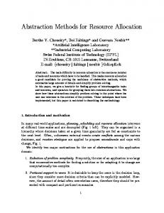
The system model.
II. S YSTEM M ODEL Consider a system shown as in Figure 1, each cell is divided into three sectors and each sector is covered by a 120-degree directional antenna. Therefore, each sector has two adjacent ones. We assume that there are 𝑀 users in a sector and they share 𝐿 PRBs for data transmission. Each user can be only allocated to consecutive PRBs as required by L-FDMA in LTE uplink. In LTE uplink, the overall transmission power is uniformly distributed among the subcarriers allocated to the same user. Denote 𝑃𝑚 and 𝒦𝑚 to be the overall transmission power and the set of consecutive PRBs assigned to user 𝑚, respectively. Then the transmission 𝑃𝑚 , power of each subcarrier for user 𝑚 is 𝑃𝑚,𝑖 = 12∣𝒦 𝑚∣ where ∣𝒦𝑚 ∣ is the number of PRBs in the set of 𝒦𝑚 . The SINR at the 𝑖th subcarrier of the 𝑛th PRB corresponding to user 𝑚 will be 𝑃𝑚,𝑖 𝐺𝑚,𝑖 𝐺(𝜃) (𝑚) 𝛾𝑖,𝑛 = , (1) (𝑚) 𝐼𝑖,𝑛 + 𝑃𝑁 where 𝐺𝑚,𝑖 is the channel gain from user 𝑚 to its base station, including pathloss, shadowing, and multipath fading, 𝐺(𝜃) is the antenna gain from user 𝑚 to its (𝑚) service base station. 𝐼𝑖,𝑛 is the power of interference from users in other sectors using the same PRB as user 𝑚, and 𝑃𝑁 is the power of additive white Gaussian noise (AWGN). The transmission data rate of user 𝑚 can be expressed as ( ) 𝛾 (𝑃𝑚 , 𝒦𝑚 ) 𝑅 (𝑃𝑚 , 𝒦𝑚 ) = 𝐵 ∣𝒦𝑚 ∣ log2 1 + , (2) Γ where 𝐵 is the effective bandwidth of each PRB, Γ is the SINR gap to satisfy block-error rate (BLER)
© 2011 ACADEMY PUBLISHER
𝒦𝑖 ∩ 𝒦𝑗 = ∅ ∀𝑖 ∕= 𝑗, 𝑖, 𝑗 ∈ {1, 2, ..., 𝑀 },
(5)
𝑃𝑚 ≤ 𝑃𝑚𝑎𝑥 ,
(6)
where 𝑃max is the power threshold for each user. Constraint (5) indicates that each PRB can only be allocated to one user in a sector. III. J OINT POWER CONTROL AND RESOURCE ALLOCATION
In this section, we will first introduce the fractional power control in LTE uplink and then present our proposed resource allocation scheme. Fractional power control is suggested by LTE working groups, which can be expressed as [2] 𝑃𝑚= min{𝑃max , 𝑃0+𝛼𝑃 𝐿+10 log10 ∣𝒦𝑚∣+Δ𝑚𝑐𝑠 +𝑓 (Δ𝑖 )}, (7) where 𝑃0 is a cell-specific parameter decided by the higher layers, 𝛼 is a compensation parameter that is chosen from set {0, 0.4, 0.5, 0.6, 0.7, 0.8, 0.9, 1} and decided by the base station of the serving cell, 𝑃 𝐿 is the pathloss from user 𝑚 to its base station, Δ𝑚𝑐𝑠 is a transport format (TF) dependent offset used to consider different SINR requirements for various MCSs, and 𝑓 (Δ𝑖 ) represents the correction value provided by close-loop power control. The objective of the power control in LTE uplink is to limit inter-cell interference and to maintain SINR requirements based on the QoS constraint, cell load, and user equipment power capabilities. In general, power control in uplink determines the average SINR range a user is operating at. Using fractional power control to limit interference with other sectors can simplify the resource allocation for cellular systems. However, the inter-cell interference is still very strong since resource allocation is performed without considering adjacent sectors, especially when
JOURNAL OF COMMUNICATIONS, VOL. 6, NO. 4, JULY 2011
303
two or more edge users in adjacent sectors are using the same PRBs. In this paper, we develop an adaptive PRB allocation method that will adjust the PRBs used by cell-edge users with the help of information on the allocated PRBs and users’ positions in adjacent cells obtained through X2 interface. Each sector first performs resource allocation independently based on proportional fairness introduced in Section II while fractional power control is used. PRBs for the adjacent edge users are jointly adjusted based on users’ position and initial PRB allocation. Users’ position can be obtained at the base station side. As the shadow area in Figure 1, we assume that there is a primary sector among every three adjacent sectors of different cells. The primary sector will collect information of resource allocation and users’ position of the coordination sectors and perform PRB rescheduling. Since PRB adjustment may change interference environment of the center users, we will finally re-allocate the transmission power for center users. There will be severe inter-cell interference if the same PRB is used by two or three edge users in adjacent sectors who have different closest adjacent base stations. For example, user equipment (UE) 1′ in Sector 2 is close to Sector 1 and UE 3′′ in Sector 3 is close to Sector 2 in Figure 1. If UEs 1′ and 3′′ use the same band, there will be severe interference. UE 3′′ will cause severe interference to UE 1′′ . Therefore, PRBs in this case need to be re-allocated. We assume that two edge users at adjacent sectors with different base stations may use the same PRB simultaneously if there is no severe interference with each other, as UE 1′′ and UE 1′ in Figure 1. After PRB reallocation and power control, we will further consider MCS adaption in each sector. Each sector will choose an MCS to maximize the throughput based on the SINR. The throughput is determined by the initial BLER (IBLER) for the UE with allocated PRBs and transmission power and can be expressed as, max 𝑇 (𝑖) = 𝑅(𝑖)(1 − 𝑃 (𝑖, 𝛾𝑒,𝑖 )), 𝑖
(8)
where 𝑖 is the MCS index in LTE, 𝑅(𝑖) is the data rate achieved by using MCS 𝑖, 𝛾𝑒,𝑖 is the exponential effective SINR achieved by using MCS 𝑖 as expressed in Equation (3), 𝑃 (𝑖, 𝛾𝑒,𝑖 ) is the IBLER for the used blocks. From [10], the IBLER for each block can be approximated by ( ) 𝛾𝑒,𝑖 − 𝑏𝑖 1 √ , (9) 𝑃𝑏 (𝑖, 𝛾𝑒,𝑖 ) = erfc 2 2𝑐𝑖 where 𝑏𝑖 and 𝑐𝑖 are parameters obtained by curve-fitting corresponding to MCS 𝑖. Consequently, the IBLER for © 2011 ACADEMY PUBLISHER
the user with MCS 𝑖 can be expressed as 𝑃 (𝑖, 𝛾𝑒,𝑖 ) = 1 − (1 − 𝑃𝑏 (𝑖, 𝛾𝑒,𝑖 ))∣𝒦𝑚 ∣ .
The proposed scheme can be summarized as following. ∙ Step 1: Each sector performs independent power control and resource allocation. For example, three sectors in shadow area shown in Figure 1 perform independent power control and resource allocation based on proportional fairness introduced in Section II. ∙ Step 2: Exchange information on resource allocation and users’ position of the sectors to the primary sector. For example, Sectors 2 and 3 send the information on PRB allocation and users’ position to Sector 1. ∙ Step 3: The primary sector re-allocates the PRBs based on the information and sends back the final resource allocation information to the other two sectors. For example, Sector 1 re-allocates the PRBs based on the information received from Sectors 2 and 3 and sends the adjusted PRB allocation information to these two sectors. The detailed reallocation algorithm is shown in Table 1. The PRB allocation matrix is the index of PRBs allocated to each user in the sectors. Users’ position matrix is about the position of users in each sector. From this matrix we can know the closest interference sector of each user. ∙ Step 4: The coordinate sectors adjust the transmission power of their center users based on the information from the primary sector. ∙ Step 5: All sectors perform adaptive MCS allocation and the users transmit data based on the information from their base stations. IV. S IMULATION R ESULTS In this section, we will compare performance of our scheme with independent resource allocation with fractional power control and SFR [4]. For SFR, the transmission power for the edge users is larger than that of the center users. We consider the system as shown in Figure 1, where a half of sector users are randomly distributed at the edge and the other half are randomly distributed in the center. The edge area is assumed to be the outer one third of the whole sector area. The major simulation parameters are summarized in Table 2. Since each user can only use consecutive PRBs in LTE uplink, the optimal algorithm for resource allocation is an NP-hard problem [6]. There are several sub-optimal algorithms with only a little performance degradation but with much lower complexity. It has been shown in [6]
304
JOURNAL OF COMMUNICATIONS, VOL. 6, NO. 4, JULY 2011
TABLE I R E - ALLOCATION ALGORITHM
Proposed allocation Independent allocation SFR
3.5
3 Spectral efficiency (bit/s/Hz)
Algorithm Re-allocation Input: PRB allocation matrix 𝐽 and users’ position matrix 𝑃 Output: PRB re-allocation matrix 𝐽𝑛 1. Get the matrix of closest adjacent sector number 𝑁 for each user based on 𝑃 (𝑁𝑖 for user 𝑖) 2. for sector=1 to 3 do 3. find PRBs used by two edge users 𝑖 and 𝑗 4. if 𝑁𝑖 ∕= 𝑁𝑗 5. switch the PRB of user 𝑖 with a PRB used by its center user 6. end if 7. end for 8. return 𝐽𝑛
4
All users 2.5
2
1.5
1
0.5 Edge users 0 −190
−188
−186
−184
−182
−180 −178 N0 (dBm/Hz)
−176
−174
−172
−170
(a) M=6 4
3.5
TABLE II M AIN S IMULATION PARAMETERS
Parameter Bandwidth Carrier frequency Total number of PRBs Cell radius Ratio of cell edge area Distance-dependent pathloss Shadowing standard deviation PSD of thermal noise 𝑃0 𝛼
Value 10 MHz 2 GHz 48 PRBs (PUSCH) 500 m 1/3 128.1+37.6𝑙𝑜𝑔10(𝑑) d in Km 8 dB −174 dBm/Hz -80 dBm 0.7
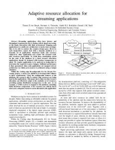
that grouping algorithm, which allocates equal number of consecutive PRBs to each user, performs the best among these suboptimal ones. Hence, we will use it to allocate PRBs in our simulation. Fractional power control is used for independent resource scheduling. We assume the cell load is larger than 80%, and all the users in a sector are allocated the same number of PRBs, which is consistent with the grouping algorithm. Figure 2 demonstrates spectrum efficiency of the three schemes versus the power spectral density (PSD) of channel noise when there are 6 users and 8 users, respectively. We assume that there are six users in a sector with three on the edge. From the figure, our scheme improves both the spectrum efficiency for the edge users and overall spectrum efficiency. It increases 20% over the independent resource allocation and about 10% over SFR for edge users’ spectrum efficiency. We can also see that the proposed scheme performs better when the
© 2011 ACADEMY PUBLISHER
Spectral efficiency (bit/s/Hz)
3
2.5 All users 2
1.5
1
Proposed allocation Independent allocation SFR
Edge users 0.5
0 −190
−188
−186
−184
−182
−180 −178 N0 (dBm/Hz)
−176
−174
−172
−170
(b) M=8 Fig. 2. Spectral efficiency of different schemes versus noisy density for different number of users.
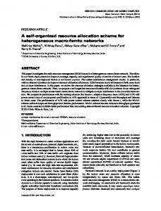
system is interference dominant, which corresponds to the case with lower noise PSD in the figure. Figure 3 shows spectrum efficiency versus the number of users with noise PSD of −174 dBm and −185 dBm, respectively. From the figure, the performance gain of our scheme increases with the number of users. It can be easily seen that the information exchanged between sectors is pretty limited, only several hundred bits for 10 users in a sector. For example, if using 6 bits for user index, information exchanged for 48 PRBs will be 288 bits. V. C ONCLUSION In this paper, we have introduced a resource allocation scheme for LTE uplink systems. The proposed scheme first allocates PRBs in each cell independently, then adjusts the PRBs and perform power control for the center users based on information on PRB allocation and users’ position among adjacent cells. Simulation results have indicated that our scheme can improve spectrum efficiency for edge users and overall spectrum efficiency
JOURNAL OF COMMUNICATIONS, VOL. 6, NO. 4, JULY 2011
305
4 Proposed allocation Independent allocation SFR
3.5
All users
Spectral efficiency (bit/s/Hz)
3
2.5
2
1.5
1
0.5
0
Edge users
2
3
4
5 M
6
7
8
(a) 𝑁0 = −174 dBm/Hz 4 Proposed allocation Independent allocation SFR
3.5
All users
Spectral efficiency (bit/s/Hz)
3
2.5
2
1.5
1 Edge users 0.5
0
2
3
4
5 M
6
7
8
(b) 𝑁0 = −185 dBm/Hz Fig. 3. Spectral efficiency comparison of different schemes for different numbers of users.
compared with independent resource allocation and SFR. Since we have considered all constraints in LTE uplink, the proposed algorithm is ready to be used in real systems for performance improvement. R EFERENCES [1] 3GPP TS 36.300 V9.0.0 “Evolved universal terrestrial radio access (E-UTRA) and evolved universal terrestrial radio access network (E-UTRAN); overall description; Release 9,” June 2009. [2] 3GPP TS 36.213 V9.0.0 “Evolved universal terrestrial radio access (E-UTRA); physical layer procedures; Release 9,” Dec. 2009. [3] H. G. Myung, J. Lim, and David J. Goodman, “Single carrier FDMA for uplink wireless transmission,” IEEE Veh. Tech. Mag., vol.1, no.3, pp. 30–38, 2006. [4] R1-050507,“Soft frequency reuse scheme for UTRAN LTE,” Huawei. 3GPP TSG RAN WG1 Meeting, Athens, Greece, May 2005. [5] X. Mao, A. Maaref, and K. Teo,“Adaptive soft frequency reuse for inter-cell interference coordination in SC-FDMA based 3GPP LTE uplink,” in Proc. of IEEE GLOBECOM 2008, Nov. 2008, pp. 1–6.
© 2011 ACADEMY PUBLISHER
[6] S. Lee, I. Pefkianakis, A. Meyerson, S. Xu, and S. Lu, “Proportional fair frequency-domain packet scheduling for 3GPP LTE uplink,” in Proc. of IEEE INFOCOM, Apr. 2009. [7] R. Giuliano and F. Mazzenga, “Exponential effective SINR approximations for OFDM/OFDMA-based cellular system planning,” IEEE Trans. Wireless Commu., vol.8, no.9, pp. 4434–4439, 2009. [8] X. Qiu and K. Chawla, “On the Performance of Adaptive Modulation in Cellular Systems,” IEEE Trans. Commu., vol. 47, no.6, pp. 884–895, June. 1999. [9] I. C. Wong, O. Oteri, and W. McCoy, “Optimal resource allocation in uplink SC-FDMA systems,” IEEE Trans. Wireless Commu., vol.8, no.5, pp. 2161–2165, May 2009. [10] K. Sayana, J. Zhang, and K. Stewart, “Link performance abstraction based on mean mutual information per bit (MMIB) of the LLR channel,” IEEE 802.16 Broadband Wireless Access Working Group.