UNU/IIST International Institute for Software Technology
A Predicative Semantic Model for Integrating UML Models Jing Yang, Quan Long, Zhiming Liu and Xiaoshan Li September 2004
UNU-IIST Report No. 309
R
UNU-IIST and UNU-IIST Reports UNU-IIST (United Nations University International Institute for Software Technology) is a Research and Training Centre of the United Nations University (UNU). It is based in Macau, and was founded in 1991. It started operations in July 1992. UNU-IIST is jointly funded by the Governor of Macau and the governments of the People’s Republic of China and Portugal through a contribution to the UNU Endownment Fund. As well as providing two-thirds of the endownment fund, the Macau authorities also supply UNU-IIST with its office premises and furniture and subsidise fellow accommodation. The mission of UNU-IIST is to assist developing countries in the application and development of software technology. UNU-IIST contributes through its programmatic activities: 1. Advanced development projects, in which software techniques supported by tools are applied, 2. Research projects, in which new techniques for software development are investigated, 3. Curriculum development projects, in which courses of software technology for universities in developing countries are developed, 4. University development projects, which complement the curriculum development projects by aiming to strengthen all aspects of computer science teaching in universities in developing countries, 5. Schools and Courses, which typically teach advanced software development techniques, 6. Events, in which conferences and workshops are organised or supported by UNU-IIST, and 7. Dissemination, in which UNU-IIST regularly distributes to developing countries information on international progress of software technology. Fellows, who are young scientists and engineers from developing countries, are invited to actively participate in all these projects. By doing the projects they are trained. At present, the technical focus of UNU-IIST is on formal methods for software development. UNU-IIST is an internationally recognised center in the area of formal methods. However, no software technique is universally applicable. We are prepared to choose complementary techniques for our projects, if necessary. UNU-IIST produces a report series. Reports are either Research R , Technical T , Compendia C or Administrative A . They are records of UNU-IIST activities and research and development achievements. Many of the reports are also published in conference proceedings and journals. Please write to UNU-IIST at P.O. Box 3058, Macau or visit UNU-IIST’s home page: http://www.iist.unu.edu, if you would like to know more about UNU-IIST and its report series.
Chris George, Acting Director
UNU/IIST International Institute for Software Technology
P.O. Box 3058 Macau
A Predicative Semantic Model for Integrating UML Models Jing Yang, Quan Long, Zhiming Liu and Xiaoshan Li
Abstract This paper presents a predicative semantic model for integrating models from UML class diagrams and sequence diagrams. The integrated model is used for dealing with consistency problems of UML class diagrams and sequence diagrams. We also define the notion of consistent refinement of these integrated models.
Jing Yang is a fellow of UNU-IIST from Guizhou University, Guiyang, China, where she is an Associate Professor. Her research interests include the semantics of interaction diagrams in UML and its refinement and wavelet theory and its application. E-mail:
[email protected]. Quan Long is a fellow of UNU-IIST from Peking University, Beijing, China, where he is a doctorial candidate. His research interests include Software development process and formal techniques for Object Oriented, UML and Component based Software. E-mail:
[email protected]. Zhiming Liu is a research fellow at UNU/IIST, on leave from Department of Computer Science at the University of Liecester, Liecester, England where he is lecture in computer science. His research interests include theory of computing systems, including sound methods for specification, verification and refinement of fault-tolerant, real-time and concurrent systems, and formal techniques for OO development. His teaching interests are Communication and Concurrency, Concurrent and Distributed Programming, Internet Security, Software Engineering, Formal specification and Design of Computer Systems. E-mail:
[email protected]. Xiaoshan Li is an Associate Professor at the University of Macau. His research areas are interval temporal logic, formal specification and simulation of computer systems, formal methods in system design and implementation. E-mail:
[email protected].
c 2004 by UNU-IIST, Jing Yang, Quan Long, Zhiming Liu and Xiaoshan Li Copyright °
Contents
i
Contents 1 Introduction 2 The Theoretical Basics 2.1 An Overview of OOL . . . . . . 2.1.1 Object-oriented systems. 2.1.2 Expressions. . . . . . . . 2.1.3 Class declarations. . . . 2.1.4 Commands. . . . . . . .
1 . . . . .
. . . . .
. . . . .
. . . . .
. . . . .
. . . . .
. . . . .
. . . . .
. . . . .
. . . . .
. . . . .
. . . . .
. . . . .
. . . . .
. . . . .
. . . . .
. . . . .
. . . . .
2 3 3 3 4 4
3 A Formal Syntax and Semantics of UML Models 3.1 Syntax of class diagrams . . . . . . . . . . . . . . . 3.2 Syntax of sequence diagrams . . . . . . . . . . . . 3.3 Well-formedness of sequence diagrams . . . . . . . 3.3.1 Definition 1 (Directly invoke) . . . . . . . . 3.3.2 Definition 2 (Directly follow) . . . . . . . . 3.4 Requirement models in UML . . . . . . . . . . . . 3.5 Design models in UML . . . . . . . . . . . . . . . . 3.6 OOL Semantics for UML Models . . . . . . . . . . 3.6.1 Example 1 . . . . . . . . . . . . . . . . . . .
. . . . . . . . .
. . . . . . . . .
. . . . . . . . .
. . . . . . . . .
. . . . . . . . .
. . . . . . . . .
. . . . . . . . .
. . . . . . . . .
. . . . . . . . .
. . . . . . . . .
. . . . . . . . .
. . . . . . . . .
. . . . . . . . .
. . . . . . . . .
. . . . . . . . .
. . . . . . . . .
. . . . . . . . .
5 5 6 9 9 10 10 12 13 15
. . . . .
. . . . .
. . . . .
. . . . .
. . . . .
. . . . .
. . . . .
. . . . .
. . . . .
. . . . .
4 Model Refinement 16 4.0.2 Example 2 . . . . . . . . . . . . . . . . . . . . . . . . . . . . . . . . . . . . 18 5 Conclusions and Future Works
Report No. 309, September 2004
19
UNU-IIST, P.O. Box 3058, Macau
Introduction
1
1
Introduction
In a UML-based development process, such as the RUP [24, 14], several kinds of UML models are used to represent and analysis the artifacts created in a certain phase of the system development, which reflect the multiple views of UML: • Static view : class diagram for static analysis. • Interactive view : sequence diagrams and collaboration diagrams for interactions between objects. • Behavioral view : state machines for dynamic behavioral specification and validation. • Functional view : OCL [26] specifications for functionalities of objects. Under the multiple views of UML, the developers can decompose a software design into smaller parts of manageable scales. However, several challenging issues inevitably arise from such a multi-view approach [21]: • Consistency: the models of various views need to be syntactically and semantically compatible with each other (i.e. horizontal consistency)[20, 9, 1]. • Transformation and evolution: a model must be semantically consistent with its refinement (i.e. vertical consistency)[9, 1]. • Traceability: a change in the model of a particular view leads to corresponding consistent changes in the models of other views. • Integration: models of different views need to be seamlessly integrated before software production. Consistency checking and formal analysis of UML models have been widely studied in recent years [6, 4, 9, 23, 1]. A formal semantic model is needed for precise and intensive treatment of the problems. The informal semantics of UML is deliberately left flexible and extendable in order to allow UML to be used for different purposes, such as for requirement analysis, refinement of designs, and for code generation and testing. The majority of the existing works on formal support to UML-based development, e.g.[7, 2, 6, 5, 10, 23], focus on the formalization of individual diagrams and only treat the consistency of the models of one or two views. Another phenomenon in research on formal use of UML is that different communities intend to emphasize different notations and use the full or even extended power of, say sequence diagrams or state machines. This would lose the advantages of the multiple-view modelling. It also leads to the increase in the complexity of a certain kind of models and the reduction of the role that the other kinds of UML models can play. To our
Report No. 309, September 2004
UNU-IIST, P.O. Box 3058, Macau
The Theoretical Basics
2
knowledge, there is little work on consistent refinement of complete UML models of systems. A complete model of a system here means a family of models for the different views of the system. This paper is towards the development of a semantic model of UML. The primary use of this model is for model integration, refinement and code generation [22]. The integration is based on the object-oriented specification language (OOL) defined in [13] that is designed for objectoriented system development in general. The refinement calculus for OOL [11, 13] will be used to define consistent refinement of UML models. The refinement process will preserve the consistency and the correctness of the system. The proposed techniques are also intended to support model-driven development [25] for executable UML models. As a starting work towards UML model integration and code generation, in this paper we only consider sequential software systems for which the UML class diagrams and sequence diagrams are powerful enough. The future work will extend this approach to deal with concurrent systems for which we need the other UML models, i.e. component diagrams, activity diagrams and statecharts. The rest of the paper is organized as follows. Section 2 describes the theoretical basics of programming and presents an overview of OOL. Section 3 provides formalization of UML diagrams and system models using OOL semantics with the definition of model consistency. We show how a model is refined consistently in Section 4. Finally, concluding remarks are given in Section 5.
2
The Theoretical Basics
Our work is based on Hoare and He’s Unifying Theories of Programming[12], in which a program or a program command is identified as a design, which is represented by a pair (α, P ), where
• α denotes the set of variables of the program, called the alphabet of the design. • P , called the contract of the design, is a predicate of the form def p(x) ` R(x, x0 ) = (ok ∧ p(x)) ⇒ (ok 0 ∧ R(x, x0 ))
where – x and x0 stand for the initial and final values of program variables x in α, – predicate p, called the precondition of the program, characterizes the initial states in which the activation of the program will lead its execution to termination, – predicate R, called the post-condition of the program, relates the initial states of the program to its final states, and – we describe the termination behavior of a program by the Boolean variables ok and ok 0 , where the former is true if the program is properly activated and the latter becomes true if the execution of the program terminates successfully.
Report No. 309, September 2004
UNU-IIST, P.O. Box 3058, Macau
The Theoretical Basics
3
The semantics of a command c, [[c]], is an implication of the form D(c) ⇒ Spec, where D(c) defines the well-definedness of command c, Spec is a design of the form: p(x) ` R(x, x0 ). A command c1 refines c2 iff ∀x, x0 , ok, ok 0 · ([[c1 ]] ⇒ [[c2 ]]).
2.1
An Overview of OOL
OOL [13] is an object-oriented language with a rich variety of features including subtypes, reference types, visibility, inheritance, dynamic binding, polymorphism and local variable nested declarations. The language is designed for reasoning about object-oriented software at different levels of abstraction including specifications, designs and programs.
2.1.1
Object-oriented systems.
An object system (or program) S is of the form cdecls • P , where cdecls is a declaration of a finite number of classes, and P is called the main method and is of the form (glb, c) consisting of a finite set glb of global variables with their types and a command c. P can be understood as the main method if S is taken as a Java program. We do not allow any direct access to class attributes in the main method P , thus except for manipulation on variables in glb, P can only call methods of classes in the declaration section. The other syntactic categories of OOL includes class declarations, class declaration sections, commands and expressions. We treat class declarations in the same way as commands and whose semantics are to be defined as designs in terms of preconditions and postconditions. The semantics of OOL is fairly intuitive. One can informally understand the meaning of a program as the execution of its Java counterpart, once it is compiled correctly. However, it is important to note that the validity of an expression D(e) is defined and should be checked when it is evaluated. An expression e is valid only if the types and variables used in e are declared. The dynamic type of an expression is recorded during evaluation.
2.1.2
Expressions.
Expressions, which can appear on the right hand sides of assignments, are constructed according to the rules: e ::= x | null | self | e.a | f (e) where null represents the special object of the special class NULL that is a subclass of all classes and has null as its unique object, self will be used to denote the active object in the current scope, e.a is the a-attribute of e, and f (e) represents the built-in expression.
Report No. 309, September 2004
UNU-IIST, P.O. Box 3058, Macau
The Theoretical Basics
2.1.3
4
Class declarations.
A declaration cdecls is of the form: cdecls := cdecl | cdecls; cdecl, where cdecl is a class declaration of the following form Class N extends M { private U1 u1 = a1 , . . . , Um um = am ; protected V1 v1 = b1 , . . . , Vn vn = bn ; public W1 w1 = c1 , . . . , Wk wk = ck ; method m1 (T 11 x1 , T 12 y 1 , T 13 z 1 ){c1 }; ···; m` (T `1 x` , T `2 y ` , T `3 z ` ){c` } }
Note that • N and M are distinct names of classes, and M is called the direct superclass of N. • The private declaration declares the private attributes of the class, their types and initial values, and similarly, the protected and public declarations for the protected and public attributes. • The method declaration declares the methods, their value parameters T i1 xi , result parameters T i2 y i , value-result parameters T i3 zi and bodies ci . We sometimes denote a method by m(paras){c}, where paras is the list of parameters of m and c is the body command of m. • A method body ci is a command that will be defined later. The above class declaration is well-defined, if N has not been declared before, the names of the attributes are distinct, the types of the initial values of the attributes match the types of the attributes, and the names of the parameters of each methods are distinct. A class declaration section is well-defined if all the class declarations, commands and expressions in it are welldefined.
2.1.4
Commands.
Our language supports typical object-oriented programming constructs. c ::= skip | chaos | var T x=e | end x | c; c | c ¢ b ¤ c | c u c | b ∗ c| le.m(e, v, u) | le := e | C.new(x)
Report No. 309, September 2004
termination, abort, local variable declaration local variable undeclaration, sequence, conditional choice nondeterministic choice, iteration, method call assignment, creating a new object
UNU-IIST, P.O. Box 3058, Macau
A Formal Syntax and Semantics of UML Models
5
where b is a Boolean expression, e is an expression, and le is an expression which may appear on the left hand side of an assignment and is of the form le ::= x | le.a where x is a simple variable and a an attribute name. Most of the commands have their classic meanings in the imperative setting. We only explain the following commands which are typical to object-oriented programming. • An Assignment: le := e is well-defined when le and e are well-defined and the type of e is a subtype of the declared type of le. In the case of a simple assignment x := e, when the assignment is well-formed it only modifies x by assigning x with the value of e; In the case of an modification of an object’s attribute, le.a := e changes the a-attribute of the object that le refers to into the value of e. • A Method Call: A method call le.m(v, r, vr) is well-defined if le is non-null object and m(x, y, z) is a method declared in the type of le. When it is well-defined, its execution assigns the values of the actual parameters v and vr to the formal parameters x and z of m of the active objects that le refers to, and then executes the body of the method under the environment of the class of the active object. After the execution of the body terminates, the value of the result and value-result parameters y and z are passed back to the actual parameters r and vr. • An Object Creation: C.N ew(x) is well-defined if C is a declared class. Its execution creates an object of class C with a fresh reference, attaches it to variable x, and attaches the initial values of the attributes of class C to the attributes of x too.
3
A Formal Syntax and Semantics of UML Models
In this section, firstly we will give the syntax of the class diagram and sequence diagrams. After that we will describe the requirement model and design model in our framework. Finally we will investigate the conditions on the consistent issues and present the OOL semantics of a consistent model.
3.1
Syntax of class diagrams
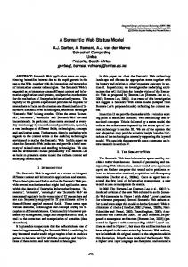
A class diagram Γ (see Fig.1 and 5) identifies the following information. 1. The first part provides the static information on classes and their inheritance relationships: • CN: the finite set of classes has always been identified. • super: this is the direct generalization relation over the set CN.
Report No. 309, September 2004
UNU-IIST, P.O. Box 3058, Macau
A Formal Syntax and Semantics of UML Models
6
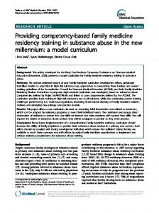
2. The second part describes the structures of classes. For each C ∈ CN, we use attr(C) to denote the set {< a1 : T1 >, · · · , < am : Tm >} of primitive attributes of C, where Ti stands for the type of attribute ai of class C. 3. The third part provides the information about associations among classes: the finite set in which elements are of the forms: < C1 , m1 , Ass, m2 , C2 > | (C1 , m1 , Ass, m2 , C2 ) The first represents a direct association Ass from C1 to C2 . The second notation indicates a undirect association Ass between classes C1 and C2 . Here m1 and m2 are of the forms: 1 | 0..1 | ∗ | 1..∗, indicating multiplicities respectively. We call undirect association conceptual association, and direct association design association. 4. For each C ∈ CN, methodC identifies the set of all methods of class C. Store
Catalog Uses 1
address name
1
Sale LogsCompleted 1
1
*
date time isComplete 1
1
Contains Has
IsPaidBy
1...*
description price upc
1
1...*
ProductSpecification
LineItem
Payment
Describes 1
*
quantity
amount
Figure 1: A conceptual class diagram for an automated checking out system in a shop The main condition of the well-formedness of a class diagram is that the inheritance relation does not introduce cycles between classes. Also we do not deal with multiple inheritance in a class diagram. The other issues are mainly naming problems. In our framework, the class diagram defines the system state space allowed by the application, and each system state encompasses some objects and all links among these objects. Therefore, the class diagram plays the role as declarations of classes, types and variables in a program. A system state is a well-typed state of the variables. We can therefore easily specify (or translate) a class diagram Γ into a declaration section cdeclΓ in OOL later.
3.2
Syntax of sequence diagrams
A sequence diagram consists of objects and ordered messages that describe how the objects communicate. An interaction occurs when one object invokes a method of another. We now
Report No. 309, September 2004
UNU-IIST, P.O. Box 3058, Macau
A Formal Syntax and Semantics of UML Models
7
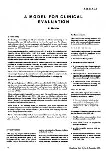
give the syntactic definition of sequence diagrams. We will allow call back messages in a sequence diagram (e.g. message “(5)” in Fig.2). The definition covers most features of UML 2.0 including combined fragments (except for the PAR one) [3], reference to other sequence diagrams and nested sequence diagrams. The object “: B” in Fig.2 represents a nested sequence diagram. A sequence diagram SD consists of two parts: 1. A sequence of objects: hobj1 , obj2 , · · · , objn i. Each object obji has the following structure: • Each object obj is associated with a type, denoted by type(obj), which is either a class name C in CN or a sequence diagram SD1 . • For each object obj, the property multiob(obj) equals true if obj is a multi-object (e.g. : C in Fig.2), otherwise multiob(obj) is false. Multi-objects represent one-to-many associations in a class diagram. • For each object obj there is a sequence of time-points hp1 , p2 , · · · , pn i which are totally ordered and represent the time points when an event occurs during the lifetime of the object. These points represent the ordering of messages sending and receiving, the combination fragments and the references to other sequence diagrams. We have a function event for each time-point p and event(p) describes what happens at time-point p. For each time-point p, event(p) can be one of the elements in the following set {send, ack, receive, receiveack, option, loop,
endfrag, ref, endref}
2. A set MSG of messages: each message msg is one of the forms (src, m, tgt), (m, tgt) or (src, m) where • src, denoted by source(msg), is a pair (obj, p) of an object and a time-point, and source(msg) = (obj, p) means that object obj is the source of the message that occurs at time-point p, and we use (obj, p).object to denote obj and (obj, p).point to denote p. • tgt is a pair (obj, p) of an object and a time-point, represented by target(msg) and • m, denoted by method(msg), is any command in OOL. Therefore, m can be a method call of the form (ass, method()) (sometimes it is simply written as ass.m()), that represents that method () of the target object is called by the source object via the association ass. Also, m can be a command, such as a design, an assignment, or any composite command of other kinds, but we require in this case the source object and the target object must be the same. This represents the execution of an internal action of the object. Finally, a message can be a return signal and in this case m is denoted as return. • A message (m, tgt) represents an incoming message to the sequence diagram and in this case m must be a method call. A message (src, m) shows an outgoing message from the sequence diagram and in this case m must be return. We do not show return in the diagram.
Report No. 309, September 2004
UNU-IIST, P.O. Box 3058, Macau
A Formal Syntax and Semantics of UML Models
:A
:B
8
:C
(0 ) :B 2
:B 1
(1 ) (2 )
(1 )
(9 )
re f (S D 1 1 )
(3 ) LO O P
*g
(4 ) (5 )
(2 ) (c a ll b a c k )
(1 0 )
(6 ) (7 )
(8 ) ,
Figure 2: An example sequence diagram Fig.2 is an example of a sequence diagram in which
• event(p) = send shows a message is sent from this position of the current object. Similarly, receive means a message is reached at this position of the object. The message between a send point and a receive point will be drawn in a solid line with arrow to the receive point in the graph. For example, the message “(1)” and “(4)” in Fig.2. • ack and receiveack points are used to denote a return message which are drawn in dotted line with open arrowhead back to the lifeline of the source object. For example, the message “(2)” and “(7)” in Fig.2. • If an event of a point is option or loop, it will be equipped with another function, guard, which maps the point to its guard that is Boolean expression of the source object’s attributes. The option combination fragment is used to represent a sequence that will be executed if the guard condition holds. An option combination fragment is used to model a “conditional choice” statement. The loop combination fragment is used to represent a repetitive sequence. The body of the fragment will continue to be executed repetitively until the guard condition becomes false. The event(p) = endfrag represents the end of a combination fragment. • event(p) is ref means that from point p the current sequence diagram begins to call another sequence diagram and endref represents the end of the call. A ref point will be equipped with a name representing the sequence diagram it calls.
Report No. 309, September 2004
UNU-IIST, P.O. Box 3058, Macau
A Formal Syntax and Semantics of UML Models
3.3
9
Well-formedness of sequence diagrams
We need to ensure that a sequence diagram is well-formed. The well-formedness is concerned with the following conditions: • For each message msg in the sequence diagram, the event of the source point of msg must be a send or ack and the event of target point of msg must be a receive or receiveack, respectively. • If a point p1 represents the beginning of combined fragments, i.e. loop or option, there must be one and exactly one corresponding endfrag point p2 on the same object such that p2 is later than p1 . • For a point p1 with event(p1 ) = ref, there must be point p2 on the same object such that event(p2 ) = endref and p2 is later than p1 . The well-formedness of the referred sub-sequence diagram is checked recursively. • If obj is a nested sequence diagram, then for every matched pair of sending and returning messages (src, m, (obj, p1 )) and ((obj, p2 ), m, tgt), there is a corresponding matched pair of messages (m, tgt1 ) and (scr1 , m) of source-less (incoming) message and target-less (outgoing) message in the sub-sequence diagram type(obj). The order of these message is preserved in the sub-sequence diagram and the sub-sequence has to be well-formed. The well-formedness of a sequence diagram has also to ensure the sequence diagram indeed represents a scenario of method calls. This means that 1). order of the message sending and receiving must be consistent, and for all messages from the same object, the earlier it is sent the earlier it is received by the target object; 2). if a message msg invokes message msg1 , then msg1 must return before msg does. For a sequence diagram, let action be the set of all its messages, combined fragments, and referred sub-sequence diagrams. For actions action0 and action1 from the same object, we use the notation returned(action0 , action1 ) representing that the execution of action0 is finished before the execution of action1 . In particular, if action0 is a message with a method call meth0 , then its corresponding return message must be received by the object before the the execution of action1 .
3.3.1
Definition 1 (Directly invoke)
Let msg0 be a message in a sequence diagram SD.
Report No. 309, September 2004
UNU-IIST, P.O. Box 3058, Macau
A Formal Syntax and Semantics of UML Models
10
• message. Message msg0 directly invokes msg1 , denoted by Invoke(msg0 , msg1 ) if target(msg0 ).object = source(msg1 ).object and target(msg0 ).point is the latest point in the set {p|p ∈ target(msg0 ).P oints ∧ p < source(msg1 ).point ∧ ¬returned(msg0 , msg1 )}
where target(msg0 ).P oints is the time-points of the target object of msg0 in SD. • fragment. Let freg be a combined fragment and (obj, p) is the beginning point for freg. We say msg0 directly invokes freg, denoted by Invoke (msg0 , freg), if target(msg0 ).object = obj and target(msg0 ).point is the latest point in the set {t|t ∈ target(msg0 ).P oints ∧ t < p ∧ ¬returned(msg0 , freg)}
• ref. Let SD1 be another sequence diagram and rf = (obj, p) is the ref point where SD is called. We say msg0 directly invokes rf, denoted by Invoke(msg0 , rf), if target(msg0 ).object = rf.object and target(msg0 ).point is the latest point in the set {p|p ∈ target(msg0 ).P oints ∧ p < rf.point ∧ ¬returned(msg0 , rf)}
3.3.2
Definition 2 (Directly follow)
Let msg0 , msg1 be two messages, source(msg0 ) = source(msg1 ). We say msg1 directly follows msg0 , denoted as Follow(msg0 , msg1 ), if source(msg1 ).point is the smallest element of the set {p|p ∈ source(msg0 ).P oints ∧ p > source(msg0 ) ∧ returned(msg0 , msg1 )}
The directly follow relationship between other actions (fragments or the references to other sequence diagrams) is similar to Definition 2.
3.4
Requirement models in UML
As in [15, 17], the development cycle of a software system starts with the construction of a requirement model RM. In UML, requirements are captured and described by a conceptual class diagram and some use cases. Conceptual class diagram is a class diagram in which every class has no method, and the associations are conceptual (i.e. undirect). Informally, such requirement model consists of a number of UML models, including a conceptual class diagram Γr , a use-case diagram Ur , a family ∆r of use-case (or system) sequence diagrams (one for each use case), and some activity diagrams if concurrency is concerned. In this paper, we do not consider
Report No. 309, September 2004
UNU-IIST, P.O. Box 3058, Macau
A Formal Syntax and Semantics of UML Models
11
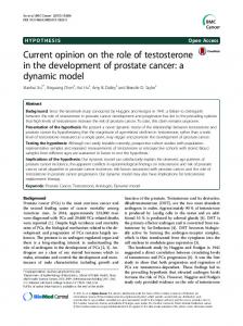
concurrency1 . We can thus denote the requirement model by a triple RM = hΓr , Ur , ∆r i. Each use case U is modelled as a use-case controller class U -Controller (see Fig. 3). Class U-Controller { private T x; method op1 (< T11 x1 >, < T12 y1 >, ){c1 }; ···; opn (< Tn1 xn >, < Tn2 yn >, ){cn } }
where the attributes x may include state control variables which are private to the controller class. For each method of the form opi (< Ti1 xi >, < Ti yi >, ){ci }, xi is a list of value parameters, yi a list of result parameters, and ci is a command.
BuyItems -Controller Bool new=true Bool isComplete =false Quantity balance=0 Quantity total=0 enterItem ( ) endSale ( ) makePayment ( ) Figure 3: The controller class for BuyItems
:BuyItems -Controller Cashier
enterItem (upc ,quantity) endSale ( )
makePayment
(amount)
Figure 4: The use-case sequence diagram for use case BuyItems
This formalization implies that all attributes and associations in other classes are directly visible to all the use-case controller classes. The use-case diagram also provides the information about the design associations among the use-case controller classes. If use case U1 includes use case U2 in the use-case diagram, then there is an association from U1 -Controller to U2 -Controller. Use-case sequence diagrams ∆r (see Fig.4), describe the the interaction between the actors and the system. Following the facade controller pattern in [15], for the operations in a use-case sequence diagram we declare the signatures in the corresponding use-case controller class. In a use-case sequence diagram, the receiver of each message is an object of the use-case controller class, and the sender is either an actor or an object of another use-case controller class. Therefore, for each use case U , U -Controller declares the operations that appear in the usecase sequence diagram and the body of each method in U -Controller is defined from the system sequence diagram of the U -Controller class. Following the idea above, given a UML requirement 1
It is often not recommended to consider concurrency at this early stage in an iterative development process.
Report No. 309, September 2004
UNU-IIST, P.O. Box 3058, Macau
A Formal Syntax and Semantics of UML Models
12
model RM = hΓr , Ur , ∆r i, the normal form specification in OOL for RM is: def [[RM]] = cdeclsΓr ; U1 -Controller; . . . ; Un -Controller
Ui , i = 1, . . . , n, are the use cases of RM. We will give the details of the meaning of [[·]] later.
3.5
Design models in UML
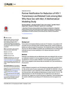
In UML, a design model DM should consist of a design class diagram Γd (see Fig.5), a family ∆d of object interaction or sequence diagrams, at least one for each method in U-Controller. We can thus define a design model as an ordered couple DM = hΓd , ∆d i. :BuyItems -Controller
Store
ProductCatalog Uses
address: Address name: Text 1
ProductSpecification
1
description: Text price: Amount upc : UPC
Has
1 1
1...*
1
LooksIn
()
Records endSale ( ) enterItem ( ) makePayment ( ) *
becomeComplete ( ) makeLineItem ( ) makePayment ( ) total( )
1
Consists
LineItem
find( upc )
makeLine Item( )
li:=new( )
quantity:Quantity subtotal( )
date: Date time: Time inComplete : Bool
1
new()
add() 1...*
Sale
1
LogsCompleted
1
1
BuyItems -Controller
:LineItem
new()
ItemsContainer items: LineItem
Contains
1
:ItemsContainer
spec :=Specification( upc )
specification( ) loadProdSpects 1
Houses
:Sale
: ProductSpecification
find()
addsale ( ) 1
enterItem (upc ,qty)
:ProductCatalog
1
IsPaidBy
Payment
1
amount:Amount
Figure 5: A design class diagram for use case BuyItems
add(li)
Figure 6: Sequence diagram for enterItem()
Object sequence diagrams ∆d operate on the design class diagram Γd . In general sequence diagrams do not contain many details for describing the functionality of the system. In an informal UML-based development, other means, such as textual description, is used to describe the functionality of the system. In our formal framework, we provide formal specification of the body of the methods that will ensure the behavior required by the sequence diagrams.
Report No. 309, September 2004
UNU-IIST, P.O. Box 3058, Macau
A Formal Syntax and Semantics of UML Models
13
Therefore, a design model DM is also specified as the normal form specification in OOL: def [[DM ]] = cdecl1 ; · · · ; cdecln
In next subsection we will give the details of the definition of [[·]].
3.6
OOL Semantics for UML Models
In this subsection we will give the OOL semantics for a UML model. A UML model is an ordered couple hΓ, ∆i. If it is a requirement model, then Γ = Γr ∪ Ur , ∆ = ∆r ; if it is a design model, then Γ = Γd , ∆ = ∆d . The semantics of a UML model hΓ, ∆i, is a sequence of class declarations in OOL, denoted by [[hΓ, ∆i]]. Before giving the semantics from a class diagram and a set of sequence diagrams, we need to ensure that these diagrams are consistent. For a well-formed class diagram and well-formed sequence diagrams, we give the following items as the definition of consistency. A violation of any of them will be considered as an inconsistency.
• Association. For each msg ∈ MSG, there must be a corresponding association in the class diagram. Notice, this is static as it cannot ensure that the object which is sending the message in a particular state during the execution is currently associated with the target object of the message. • Class Name. For the above-mentioned association, each of the two related classes in the class diagram must have the same name with the object related to msg in the sequence diagram. • Method. Each method signature in the sequence diagram must be the same as the one in the class diagram. Furthermore, if m() is the method of a message sent from : C to : D in the sequence diagram, then m() must be a method of class D in the class diagram. • Attribute. The variables used in the guard of a message should be directly accessible by the source object. • Multiplicity. If an association in class diagram is one-to-many, the corresponding object in the sequence diagram must be a multi-object. Notice that multiplicity and other general class invariants should be ensured by the design of the sequence diagram, not by the consistency checking.
Report No. 309, September 2004
UNU-IIST, P.O. Box 3058, Macau
A Formal Syntax and Semantics of UML Models
14
Now we give the semantics of consistent model hΓ, ∆i, denoted by cdeclhΓ,∆i , as follows: • Class. A class C in Γ is declared as a skeleton of class declaration cdecl in cdeclhΓ,∆i with their attributes and method signatures. All attributes are declared to be public. • Association. For association role name a from Ci to Cj in Γ, if the multiplicity of Cj is 0..1 or 1, cdecli for Ci has an attribute a with the type Cj ; and if the multiplicity of Cj is 1..∗ or ∗, cdecli for Ci has an attribute a of type Cj and an attribute a-set of type of the powerset PCj . • Constraints: Constraints, such as invariants, multiplicity and aggregation, are specified in terms of pre-post conditions of methods in OOL. • Reference attributes: For a sequence diagram SD ∈ ∆, a method of an object of type C1 is called by an object of type C2 , there will be an attribute with the reference type of C1 in the class declaration for C2 . • Method bodies: The method bodies in each class will be determined by the scenarios of method call in sequence diagrams ∆. – Directly invoked actions: For a message msg = (src, m, tgt) ∈ ∆, if m is a method signature, SD is a particular sequence diagram in which m is called, then the following sequence of actions, denoted by bodySD , is a path of the execution of an invocation of m; action1 ; action2 ; · · · actionn where Invoke(msg,action1 ) and for each i : 0 < i < n, Follow(actioni , actioni+1 ), and no more actions directly follow actionn . – Method appears in several sequence diagrams. If a method m appears in several sequence diagrams, say, SD1 , SD2 , · · · , SDn ∈ ∆ and bodySD1 , bodySD2 , · · · , bodySDn are the corresponding method bodies in these sequence diagrams. Then the body of m is the non-determined choice of them: m(){uni=1 bodySDi } The overall well-formedness of the class diagram and the sequence diagrams and their consistency are ensured by the well-formedness of the OOL specification [13] obtained from the above definition. This translation can be automated and we have designed an algorithm in [22] for this purpose.
Report No. 309, September 2004
UNU-IIST, P.O. Box 3058, Macau
A Formal Syntax and Semantics of UML Models
3.6.1
15
Example 1
The model composed of the class diagram in Fig.5 and the sequence diagram in Fig.6 has the semantics in OOL as follows. Class Store { public Address address, T ext name, P roductCatalog prod, PSale sli, Sale s, BuyItems-Controller buyctr; method addSale() }
Class P roductCatalog { public PP roductSpecif ication proli, P roductSpecif ication pro; method specif ication(U P C upc, P roductSpecif ication spec){ pro.f ind(upc) } loadP rodSpects() }
Class P roductSpecif ication { private T ext description, Quantity price, U P C upc, PLineItem li, Lineitem l; method f ind(U P C upc) }
Class BuyItems − Controller { private P roductCatalog p, Sale sale; method endsale(); enterItem(U P C upc, Quantity qty){ sale := Sale.new(); var spec := p.specif ication(upc); sale.makeLineItem(spec, qty) } makeP ayment(Amount amount, Amount balance) }
Report No. 309, September 2004
UNU-IIST, P.O. Box 3058, Macau
Model Refinement
16
Class Sale { public Date date, T ime time, Bool inComplete, ItemContainer icont, PLineItem lset, LineItem lineItem, P ayment p; method new(){ lineitem := LineItem.new() } makeLineItem(P roductSpecif ication spec, Amount total){ var li := lineItem.new(); icont.add(li) } makeP ayment(Amount amount, Amount balance); becomeComplete(); total() }
Class LineItem { public Quantity quantity; method subtotal(Quantity quantity, Quantity price, Amount subtotal) }
Class P ayment { public Amount amount; method }
Class ItemContainer { public PLineitem items, Lineitem item; method add(LineItem item, PLineItme items) }
4
Model Refinement
Having given the definition of the semantics [[·]] for UML models in the above section, now we can define the refinement and correct relationship between UML models. Firstly, let us recall the following two refinement definitions in OOL[13]. Definition 3 (Refinement between object systems) Let S1 and S2 be object programs which the same set of global variables glb. S1 is a refinement of S2 , denoted by S1 wsys S2 , if the behavior of S1 is more predictable and controllable than that of S2 . def
S1 wsys S2 = ∀x, x0 , ok, ok 0 · (S1 ⇒ S2 ) where x are the variables in glb. This means the external behavior of S1 , i.e.the pair of pre- and post-global states, is a subset of that of S2 .
Report No. 309, September 2004
UNU-IIST, P.O. Box 3058, Macau
Model Refinement
17
Definition 4 (Refinement between declaration sections) Let cdecls1 and cdecls2 be two declaration sections. cdecls1 is a refinement of cdecls2 , denoted by cdecls1 wclass cdecls2 , if the former can replace the latter in any object system: def
cdecls1 wclass cdecls2 = ∀P · (cdecls1 • P wsys cdecls2 • P ) where P stands for a main method (glb, c). Intuitively, it states that cdecls1 supports at least the same set of service as cdecls2 . Now we provide the definitions of model refinement and correctness. Definition 5 (Model refinement) Let hΓ1 , ∆1 i and hΓ2 , ∆2 i be two UML models. hΓ2 , ∆2 i is refined by hΓ1 , ∆1 i, denoted by hΓ1 , ∆1 i wmodel hΓ2 , ∆2 iif the former’s semantics refines the latter’s: def
hΓ1 , ∆1 i wmodel hΓ2 , ∆2 i = [[hΓ1 , ∆1 i]] wclass [[hΓ2 , ∆2 i]] Definition 6 (Correct Design Model) A design model DM is correct with respect to the requirement model RM, denoted by Correct(DM, RM ) if it is a model refinement of RM : def
Correct(DM, RM ) = [[DM ]] wmodel [[RM ]] As before-mentioned, the normal form specifications in OOL for requirement model and design model only concern the class declaration in an object program and its main method corresponds to the application program using services which are provided by the methods of the classes in the design model. Thus, in this article, we are only interested in refinement relation between declaration sections. We allow the following refinement rules to a declaration section within the UML framework. 1. Adding a class declaration: this corresponds to adding a class into the class diagram, the methods of the new class into sequence diagrams. 2. Introducing a fresh attribute to a class: this corresponds to adding a fresh attribute of primitive type to the class or adding a design association from the class to another. 3. Introducing inheritance. If none of the attribute of class N is appeared in class M or any superclass of M , we can make M a direct superclass of N . 4. Moving some attributes from a class to its direct superclass: if all subclasses of class N have a common attribute, the common attribute can be moved to class N from all of its subclasses.
Report No. 309, September 2004
UNU-IIST, P.O. Box 3058, Macau
Model Refinement
18
5. Data encapsulation: Suppose class M has a public attribute, and no method of other classes accesses this attribute except those of subclasses of M , we change the visibility of this attribute from public to protected. Suppose class M has a protected attribute, and no method of its subclasses accesses this attribute, we change the visibility of this attribute from protected to private. 6. Adding a fresh method into a class: This approach allows us to add a method signature into the class in the class diagram, and add a sequence diagram. 7. Refining the body command of a method m(){c} in a declared class. This may lead to the replacement of the subsequence diagrams involving with m(). 8. Moving a method from a class to its direct superclass if the method body does not access any protected or private attribute of the class. 9. Copying a method from a class to its direct subclass. 10. Delegating some tasks of a class to its associated classes. If a method of a class contains a sub-command that can be realized by a method of another class, we can replace that sub-command with a method invocation to the latter class. Notice the sequence diagrams involved the method should be refined too. 11. Removing unused attributes: for a private attribute, it can be dropped if it does not appear in any method of the class; for a protected attribute, it can be dropped if it does not appear in any method of the class and its subclasses; for a public attribute, it can be dropped if it does not appear in any method of any class. 12. Removing unused methods: if a method is not called by other method or the main method in the object program, the method can be removed.
4.0.2
Example 2
The conceptual class diagram in Fig.1, the system sequence diagram in Fig.4 together with the use-case diagram BuyItems-Controller in Fig.3 form a requirement model. We can apply the refinement calculus to this model for the design of the method enterItem() (similarly to methods endSale and makePayment) according to the design class diagram in Fig.5, then achieve the object sequence diagram in Fig.6 step by step:
1. BuyItems-Controller delegates the responsibility of creating a new sale to Sale, 2. BuyItems-Controller delegates the job of finding the specification using upc matching to Catalog, which delegates the job further to the multi-object with type of ProductSpecification, 3. BuyItems-Controller delegates the task of making a line item to Sale.
Report No. 309, September 2004
UNU-IIST, P.O. Box 3058, Macau
Conclusions and Future Works
5
19
Conclusions and Future Works
This work is towards a formal foundation for component and object systems development based on the formal object-oriented specification notation OOL and its refinement calculus in [13, 11]. In OOL, normal form specification of an object system is a sequence of class declarations and a main method. Each class declaration consists of some attributes, method signatures and methodbody definitions, which has corresponding notations in UML. In this paper, we focused on the formalization of UML class models and sequence diagrams in OOL. With this formalization, we can integrate these two kinds of UML models and carry out consistent refinement of these diagrams. The consistency conditions between these two kinds UML models are treated as the well-formedness conditions of their corresponding integrated specification in OOL. Compared to most exitsing work, e.g. [6, 4, 9, 23, 1], our approach is also transformational. However, we also provide integration of UML models. Furthermore, because different sections in an OOL specification clearly corresponding different UML diagrams, the formal specification of the integrated model can be transformed back to UML diagrams, i.e. the transformation is reversible. This is very important, as this allows up to obtain refined UML diagrams from a refined OOL specification. Thus, this approach also support re-engineering. In our formalization, the horizontal consistency is mainly static: the syntactic consistency can be checked statically using an algorithm, while the invariants can be verified with model-checking tools. Vertical consistency (of refinement) is mainly semantic. This has fully justified our use of predicates in meeting the challenge of UML formalization [7]. Fundamental techniques of program and data refinement can be applied to UML transformation. This also supports UMLbased model-driven development [8, 21]. Our future work will also include the integration of activity diagrams (for concurrency) in the framework and the extension of OOL with the notation of components to support component diagrams in UML2.0. Tools have also been developed using this framework [27]. In our related works, general transition systems are introduced to provide an integrated model of conceptual class diagrams and use cases (without the treatment of sequence diagrams, state machines and use-case diagrams)[19]. A version of OOL without reference types is presented in [11] and used in [18] for the specification of the integrated model of [19]. Article [16] uses OOL for the specification of design class diagram and sequence diagrams, but without rules for model transformation.
References [1] R. Back, A. Mikhajlova, and J. von Wright. Class refinement as semantics of correct object substitutability. Formal Aspects of Computing, 2:18–40, 2000. [2] R.J.R. Back, L. Petre, and I.P. Paltor. Formalizing UML use cases in the refinement
Report No. 309, September 2004
UNU-IIST, P.O. Box 3058, Macau
References
20
calculus. In Proc. UML’99. Springer-Verlag, 1999. [3] Donald Bell. Uml’s sequence diagram. Technical Report 3101, IBM, 2004. [4] S.Tyszberowicz B.Litvak and A.Yehudai. Behavioral consistency validation of uml diagrams. In 1st IEEE International Conference on Software Engineering and Formal Methods(SEFM), pages 118-125. IEEE Computer Society, 2003. [5] A. Egyed. Scalable consistency checking between diagrams: The Viewintegra approach. In Proc. 16th IEEE ASE, San Diego, USA, 2001. [6] G. Engels, et al. A methodology for specifying and analyzing consistency of object-oriented behavioral models. In The Proc. FSE-10, Austria, 2001. [7] A. Evans, et al. Developing the UML as a formal modelling notation. In Proc. UML’98, LNCS 1618. Springer-Verlag, 1998. [8] M. Fowler. What is the point of UML. In P. Srevens, J. Whittle, and G. Booch, editors, 2003 -The Unified Modeling Language, 6th International Conference, LNCS 2863, San Fancisco, CA, USA, 2003. Springer. [9] J.M.Kuester G.Engels and L.Groenewegen. Consistent interaction of software components. In IDPT2002, 2002. [10] D. Harel and B. Rumpe. Modeling languages: Syntax, semantics and all that stuff - part I: The basic stuff. Technical Report MCS00-16, The Weizmann Institute of Science, Israel, September 2000. [11] J. He, Z. Liu, and X. Li. Towards a refinement calculus for object-oriented systems (invited talk). In Proc. ICCI02, Alberta, Canada. IEEE Computer Society, 2002. [12] C.A.R. Hoare and J. He. Unifying Theories of Programming. Prentice-Hall, 1998. [13] Z.Liu J.He and X.Li. A predictive calculus for object-oriented system development. UNU/IIST, P.O. Box 3058, Macao. Submitted for publication, 2004. [14] P. Kruchten. The Rational Unified Process – An Introduction (2nd Edition). AddisonWesly, 2000. [15] C. Larman. Applying UML and Patterns. Prentice-Hall International, 2001. [16] J. Liu, Z. Liu, and J. He. Linking UML models of designs and requirements. UNU/IIST, P.O. Box 3058, Macao. Submitted for publication, 2003. [17] Z. Liu. Object-oriented software development in UML. Technical Report UNU/IIST Report No. 259, UNU/IIST, P.O. Box 3058, Macau, SAR, P.R. China, July 2002. [18] Z. Liu, J. He, X. Li, and Y. Chen. A relational model for formal requirements analysis in UML. In J.S. Dong and J. Woodcock, editors, Formal Methods and Software Engineering, ICFEM03, LNCS 2885, pages 641–664. Springer, 2003.
Report No. 309, September 2004
UNU-IIST, P.O. Box 3058, Macau
References
21
[19] Z. Liu, X. Li, and J. He. Using transition systems to unify uml models. Technical report, Dept. of Maths and Computer Science, the University of Leicester, England., May 2002. [20] J.L.Sourruille L.Kuzniarz, G.Reggio and editors Z.Huzar. Consistency problems in umlbased software development. In Consistency Problems in UML-based Software Development: Workshop Materials, 2002. [21] S.J. Mellor and M.J. Balcer. Executable UML: a foundation for model-driven architecture. Addison-Wesley, 2002. [22] Q.Long, Z.Liu, and J.He. Consistent code generation from uml models. submitted for publication, 2004. [23] G. Reggio, et al. Towards a rigorous semantics of UML supporting its multiview approach. In H. Hussmann, editor, Proc. FASE 2001, LNCS 2029. Springer, 2001. [24] J. Rumbaugh, I. Jacobson, and G. Booch. The Unified Modelling Language Reference Manual. Addison-Wesley, 1999. [25] S.J.Mellor and M.J.Balcer. Executable UML: a foundation for model-driven architecture. Addison-Wesley, 2002. [26] J. Warmer and A. Kleppe. The Object Constraint Language: precise modeling with UML. Addison-Wesley, 1999. [27] Z.Liu X.Li and J.He. generating a propotype from uml model of system requirement. UNU/IIST, P.O. Box 3058, Macao. Submitted for publication, 2004.
Report No. 309, September 2004
UNU-IIST, P.O. Box 3058, Macau