A Process-based Software Engineering Course: Some Experimental Results Wilson P. Paula Filho Synergia Laboratory Computer Science Department Federal University of Minas Gerais Av. Antônio Carlos, 6627 Belo Horizonte - MG – Brazil Phone: +55-31-35474172
E-mail:
[email protected] ABSTRACT In this paper, we describe the application of a process-based approach to a software engineering course. We show the architecture and materials of an educational software development process, designed to meet specified educational requirements. This process was applied to two classes of an industry-oriented program in information technology, with emphasis on software engineering. We present and discuss some quantitative results collected from these experiments.
Keywords Software engineering education, software process, iteration, life cycle model, UML, SW-CMM, IEEE standards.
1. INTRODUCTION Software development processes help software engineers to meet commitments and deliver high-quality products. However, teaching students to follow defined software development processes must address several cultural issues. In many computer science programs, software engineering courses are taken near the program end; by then, most students have learned to program without any process discipline. Often, industrial training must cope with the same problem; enterprises contract training programs to remedy technical practices, to foster process improvement, or to change development processes. Process-based software engineering courses teach software engineering using a defined software process as leading thread. Approaches that are more conventional tend to offer the students and trainees disjoint knowledge chunks, whose practical utility and effectiveness might be questionable. Defined processes have documented procedures that specify what has to be done (artifacts), when (steps), and by whom (agents). They are enactable, that is, they include all the elements required for their performance by human or automated agents. By their use, the students become acquainted with their embedded standards, techniques, and practices. Thus, they earn practical knowledge, which will help them to decide about using those in their future work. Moreover, defined software processes help instructors in software engineering courses to structure effective knowledge delivery and assessment. This helps them to take the best profit of course schedules. These are usually tight, especially if software engineering is just one of many disciplines in a computer science or computer engineering program.
Commercial published processes tend to suffer from several inadequacies for this purpose. Some processes are very extensive, since their vendors intend to support a broad customer constituency. Fitting them to course schedules requires extensive trimming and tailoring. Processes that call themselves “agile” tend to focus on just a few of the relevant software engineering disciplines; for instance, privileging implementation, perhaps with some testing and design, and leaving out difficult and necessary disciplines, such as requirements elicitation, analysis and management, project management and quality management. In the second session of this paper, we review the requirements and architecture of an educational software process. The third section describes one specific educational application of this process. The fourth section presents quantitative results of the experiments performed in this application. The fifth section summarizes conclusions and proposes further studies. These experimental results are normalized by project size, measured in function points; unlike lines of code, function-points are language-, process- and technology-independent, and they are widely used and standardized, unlike other size measures, such as object or use case points. The IFPUG (International Function Point Users Group) standardizes function point counting rules; these are described, for instance, in [11]. The students themselves, in one of the standard process artifacts, counted them, and the instructor checked these counts.
2. EDUCATIONAL SOFTWARE PROCESSES 2.1 The Praxis process Praxis is a software development process aimed primarily at the education and training in software engineering, of individuals, teams, and organizations. It has been applied in undergraduate and graduate courses, as well as industrial training programs, since beta versions were available in 1998. Version 1.0, the first production version, was introduced in 2001, and the process is currently in version 2.0. Praxis has also been used as an initial process in software improvement efforts, in real-life organizations. Swallowing a complete industrial process is a tall order for most organizations, and failure in process introduction generally reinforces resistance to further improvement efforts. To achieve success in an improvement program, the organization as a whole must be educated. After being trained and mastering the process fundamentals, the organization may either switch to full
This last approach has been adopted by our own organization, the Synergia laboratory. This laboratory, manned mostly by graduate and undergraduate students, develops software and systems under contract, mostly for e-government applications.
elements, such as workflows and iterations; these architectural elements were chosen to comply with requirement sets 1 and 2. We describe the process materials, designed to meet requirement set 3. It is shown how to match Praxis iteration exit criteria to course assessment and grading. Finally, we summarize adopted standards and tools.
2.2 Requirements
2.3.2 Process life cycles
commercial processes, or tailor and enhance Praxis to cope with the organization needs.
Praxis was designed to meet the following requirements: 1.Architecture: 1.1.Complete architecture of process steps, defined by documented entry criteria, activities, artifacts (inputs and outputs) and exit criteria. 1.2.Complete mapping of key process steps onto course milestones, which might be used for establishing student commitments, assessment and grading. 1.3.Some degree of iterative nature, as far as allowed by the learning sequence. 1.4.Exposure of the students to widely recognized standards, notations, practices, and paradigms (such as UML, SW-CMM, and IEEE standards). 2.Support for projects of adequate size, offering the possibility of: 2.1.Exercising a meaningful set of important software engineering practices, in the available course time budget (assumed as equivalent to 60 to 120 lecture hours). 2.2.Developing non-trivial software products, with a typical size of 100 to 150 function points, without imposing an excessive workload. 2.3.Exercising important team-oriented practices with small student teams. 2.4.Interaction among teams, such as having one team perform quality assurance tasks on the deliverables of other teams. 3.Student and instructor support: 3.1.At least one textbook. 3.2.Student support materials, to help artifact production and quality assurance, such as standards, templates, forms and checklists. 3.3.Use of industrial-grade but affordable tools. 3.4.Additional material to help the instructors, such as slides, examples, and exercises. A detailed discussion of these requirements may be found in [14].
2.3 Architecture 2.3.1 Overview In this subsection, we discuss how Praxis addresses the above requirements. First, we distinguish the main process life cycle models, and present previous processes, whose architecture has influenced Praxis. Then we show the major process architecture
Software processes generally adopt one of the following life cycle models: waterfall, spiral, or a combination thereof. The waterfall model follows a strictly ordered sequence of steps; therefore, it is easier to map the process steps onto course milestones, such as course module endpoints or assessments. The spiral model better represents the iterative nature of real work. The work is done in cycles; in a pure spiral model, each sub-cycle delivers a subset of the product with additional functions. Therefore, if the project is terminated after a given cycle, at least a subset of the product functionality will have been implemented. Within each cycle, the steps may be sequential; but these steps may be merely conceptual, since artifact delivery and assessment are typically performed only at the cycle endings. These generally become the main process milestones.
2.3.3 Previous processes Humphrey’s PSP [6] and TSP [7] are widely known processes intended, at least primarily, for software engineering education. PSP is really a sequence of seven increasingly sophisticated process; the first six follow strict waterfall models, while the seventh includes some iterative work. All projects involve very small individual programming exercises, so that it is possible to finish ten of them in a 30- to 60-hour semester. TSP involves a larger programming exercise, performed by a team of four or five students, in three five-week cycles; within each cycle, the process follows the waterfall model. MBASE [4] was developed by B. Boehm, one of the earliest proponents of spiral processes [1]; it has also been employed in educational situations ([2], [3]). MBASE groups iterations according to four main milestones: Life Cycle Objectives, Life Cycle Architecture, Initial Operational Capability, and Product Release. These correspond to the phases of the Unified Process [9]: Inception, Elaboration, Construction, and Transition. The Unified Process became a de facto industrial process standard and was the basis for the Rational Unified Process (RUP) [10], a widely used commercial process. Notice that that the Unified Process and the RUP have significant differences, a point that is often overlooked in citations; the former is a conceptual, abstract process, whereas the latter is a much larger, enactable, concrete process, covering a much wider set of software engineering disciplines and techniques. In the Unified Process, the iterations, grouped in phases, are executed in strict sequence. Unlike the waterfall model, however, software engineers perform activities pertaining to several software engineering fields in all iterations. These fields are called workflows: Requirements, Analysis, Design, Tests, and Implementation. In the current version of the RUP, the term workflow has been replaced by discipline, as proposed by the OMG Software Process Engineering Metamodel Specification [12].
2.3.4 Praxis process elements The Praxis process is described in [15]. Its architecture borrows from the Unified Process a matrix structure, composed of sequential phases and iterative workflows (Figure 1). The Praxis phases are the same as those of the Unified Process.
freely tailored, Standard Praxis adopts preset iterations, chosen for ease of mapping to course milestones. Table 1 – Standard Praxis iterations Phase Inception
Process {Ordered} Phase
4 7
{Ordered}
1..n
Workflow
2 – LR (Requirements elicitation)
0..n +subflow
1
Iteration 1 – AT (Activation)
Iteration uses follows
1 1..n
1 Script
Practice
1..n
{Partially ordered}
Elaboration
Activity
3 – AR (Requirements analysis)
Figure 1 - Praxis process elements Praxis has also the same basic technical workflows of the Unified Process, plus three additional management-oriented workflows (Project Management, Quality Management, and Process Engineering). These additional workflows are partitioned in subworkflows, themselves closely aligned to the SW-CMM key process areas [15]. Additional system-oriented workflows, such as Business Process Modeling or Deployment, included in the RUP, were considered as out of scope for software engineering education applications. However, Praxis provides a Systems Engineering workflow; it is an empty placeholder in the standard process, but may be tailored to include such system-oriented activities. Praxis might be viewed as a tree of processes, whose root is Standard Praxis. This is described by a UML model, that defines process concepts and their relationships; by a script spreadsheet, that describes instances of specific process elements (such as iterations, workflows and artifacts); and by a standards collection.
4 – DI (Implementable design)
Construction 5 – L1 (Release 1)
Every non-root process is derived from either Standard Praxis or from other derived process, according to a set of customization rules, embedded in one of the Process Engineering standards. Derived process may change the iterations number, names, entry and exit criteria, and input and output artifacts. Artifacts might be simplified, if a more agile process is desired, or additional artifacts might be included, such as those required by systems engineering workflows. For educational purposes, however, we have found that, normally, just minor adjustments are required, in order to match iterations and course milestones under specific course constraints. For most educational applications, it suffices to tailor the script spreadsheet, and no changes are required to the process model or standards. The process includes a coding standard for Java; different coding standards must be supplied, if another language is used. The Praxis phases are divided in iterations (complete incremental steps), whose completion milestones may be mapped to course assignments. Unlike the Unified Process, whose iterations may be
Transition
6 – L2 (Release 2) n – Ln (Release n) n + 1 – TA (Alpha testing) n + 2 – TB (Beta testing) n + 3 – OP (Pilot operation)
Output Preliminary project proposal. Main portions of analysis model and requirements specification (main classes, relationships, use cases and use case flows). Preliminary internal and external design sketches. Preliminary project estimates. Complete analysis model and requirements specification, detailed at essential (problem-oriented) level. Complete development and quality assurance plans, based on estimates of size (function points), efforts, schedules, and risks. Highlevel architectural design. Complete external and internal design of critical use cases, chosen to exercise major risk aspects. Acceptance test plans. Test specification and implementation of the critical use cases. Project tracking and quality assurance. Complete implementation (detailed design and coding) and testing (unit and integration) of a meaningful subset of use cases. Project tracking and quality assurance. Same. Same. Final acceptance testing in developer environment. Final acceptance testing in target environment. Monitored product operation, enacting a maintenance process when necessary.
Table 1 summarizes the iterations in Standard Praxis. Their name is a two-letter code, based on the Portuguese acronym for the dominant activities for that iteration; they should not be interpreted as waterfall steps. In this paper, we refer to the iterations by their numbers.
2.3.5 Praxis process materials The Praxis workflows are defined as a partially ordered set of activities. In principle, the process architecture allows for the execution of any workflow activity in any iteration, but the iteration script suggests a list of preferred activities for each. The scripts also define the artifacts that are input and output in the iteration, as well as a list of entry and exit criteria. From an instructor’s viewpoint, the exit criteria define the course assessment points, while the output artifacts define a list of deliverables for each course milestone.
1..n
1 1..n
+input
1..n
1..n
1
1..n
1..n
Artifact
1..n
+entry criterion
Criterion
+exit criterion
Figure 2– Praxis script elements Praxis adopts a matching of process and course milestones similar to PSP and TSP. However, its input and output artifacts are closer to typical industrial process artifacts, since they must obey industrial-grade standards, themselves adapted from the IEEE software engineering standards [8]. Table 2 – Suggested activities for iteration 3 Workflow Requirements
Analysis
Artifact
Sections
Requirements specification
Complete.
Analysis model
Complete.
Activity
+output
0..n
Table 3 - Output artifacts for iteration 3
Requirements database Initial requirements.
executes
Script
For one sample iteration, Table 2, Table 3 and Table 4 present suggested activities, output artifacts, and exit criteria, respectively.
Suggested activities Refine interface requirements; refine functional requirements; specify nonfunctional requirements; prioritize requirements; review requirements. Refine classes; refine class organization; refine class relationships; identify attributes; identify inheritance relationships; realize use cases, review analysis model.
Design high-level architecture; define user Design interaction guidelines. Implementation Build user interface prototype. Tests
Test user interface prototype.
Project management
Build requirements database; estimate size; estimate resources; estimate schedule; analyze risks; write project development plan; write iteration report.
Quality management
Plan configuration management; check-in iteration baseline; write quality assurance plan; perform iteration quality audit.
Design description
Introduction; external design (strategies); architectural design (strategies); release plan (provisional).
Design model
Use case view; logical view (architectural level).
Project development plan
Complete.
Project estimation spreadsheet
Complete.
Project report
For this iteration.
Quality assurance plan
Complete.
Quality audit report
For this iteration.
Peer review report
For requirements specification review.
Table 4 - Exit criteria for iteration 3 Criterion
Pertinent artifacts
Requirements specification; Analysis Management review model; Project development plan; Quality assurance plan; Design description. Walkthrough
Requirements specification; Analysis model; Project development plan
Peer review Requirements specification (including (technical review or Analysis model diagrams). inspection) Quality audit
Iteration baseline.
Customer acceptance All iteration artifacts.
2.3.6 Iteration exit criteria The names of the exit criteria are those used in industrial settings; they conform to IEEE Std. 1028, the IEEE Standard for Software Reviews and Audits [8]. They must be reinterpreted in an educational environment. In industrial settings, management reviews would be less formal reviews, conducted by a software engineering team, under direction of the project leader; in the educational version, a project team is instructed to perform these reviews on their own material, using the process checklists.
Real-life walkthroughs would be performed to inform customers and other stakeholders. In the educational version, a project team performs the walkthroughs in front of the whole class, while the instructor points out deficiencies and suggests improvements. These checklists are the same used in the following peer review, performed by one of the colleague teams. The review team is held partially responsible for the quality of the reviewed material. For every defect found by the peer review team, the authoring team must either fix the defect or rebuke the finding. All of this is recorded in a standard process form, in order to ease review postprocessing and quality audits. Finally, in an industrial setting, a quality assurance group would perform the quality audit, double-checking the previous reviews, and the customer would have final acceptance word. In the educational setting, these tasks are performed by the instructor, perhaps helped by a teaching assistant.
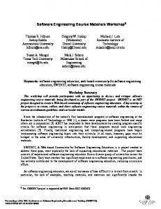
2.3.7 Process standards and tools The Praxis process roles are related to the workflows; the students may play fixed or rotated roles, but the iteration reports must show how many hours each student has worked in each workflow. These iteration reports allow the collection of project metrics and the tuning of the workload; they were the source for the quantitative results shown in Section 4. Artifact
Practice 1
1 based on
1 conforms to
conforms to
0..1
0..1
Template
0..1
Standard
explained by
Many artifacts can be built with a word processor or a spreadsheet tool; most documents have Microsoft Word templates, and most reports and spreadsheet have Microsoft Excel templates. Important exceptions are the analysis and design models, which require UML-compliant modeling tools. Commercial modeling tools tend to be quite expensive, but some vendors are willing to offer free educational licenses or free limited-capability versions. Open-source tools might become an alternative, provided they offer a minimum set of capabilities. The required capabilities include use case, class, collaboration, sequence and state diagrams, for analysis; for the design model, it is necessary to have code generation and reverse engineering for the chosen implementation language. In the application described here, we used Rational Rose as the modeling tool. A license to use the Rational Suite Enterprise was granted by IBM Rational to the Computer Science Dept. of the Federal University of Minas Gerais, within the SEED program (Software Engineering for Educational Development). We might have used other tools of the Rational Suite, such as those for requirements management, testing and document generation. We considered, however, that they would require significant time to be mastered by the students, and that this time investment would not be repaid in productivity increase, since these tasks had relatively low weight in the course workload. This situation may change in the future, as we discuss in the conclusions.
3. AN EDUCATIONAL APPLICATION 3.1 Application description
1
1
The process includes checklists for every adopted standard. The students must use these in the peer reviews. The checklists help to achieve consistent quality goals for every team, and alleviate the instructors’ workload. Most of the detailed checking is done by the peer review team; the instructor (or teaching assistant) may perform a cursory re-check of the peer review thoroughness, and check whether the defects found were either fixed or rebuked.
enforced by
0..*
0..*
Example
Checklist
Figure 3 - Praxis process materials The process artifacts conform to several standards, such as requirements specifications, project plans, quality assurance plans, design descriptions, test plans and specifications and user documentation (Figure 3). These standards conform themselves to simplified versions of the corresponding IEEE standards. For most artifacts, templates and examples are provided. In some cases, such as the software development plan and the quality assurance plan, the artifact templates are pre-filled with Standard Praxis material; these parts need be changed only in case of process tailoring. Besides the artifact standards, the process includes standards that cover important practices, such as user interface design, detailed design and coding, change management, contracting and maintenance.
In this paper, we focus on the application of process in a so-called specialization program in Information Technology, with a Software Engineering major. In the Brazilian educational system, specialization programs are industry-oriented graduate programs, ranking somewhere between the bachelor and master degrees. Most of its students expect recycling in up-to-date technologies and processes, with a stronger focus on practical aspects than regular academic graduate courses. Some of them may later apply to master programs, but the majority intends to continue a career in industry. Courses are held at nights and weekends, and most of these students have daytime jobs. Therefore, time for homework is quite limited, and the effectiveness of course delivery is especially important. A process-oriented approach was expected to lead to better ratios between knowledge acquired and time available for course projects. The experiments described here applied Praxis to two classes, in 2002. Both classes had about 25 students. In previous modules in the same program, students had received refreshment courses in object-oriented programming and other subjects, such as databases and distributed computing. Software engineering proper was taught in four 30-hour modules, totaling about one-third of the lecture-hours for the whole program.
3.2 Mapping process to course The course milestones were attached to the course modules. The first module covers the two first process iterations, since these tend to have smaller workloads. This might not be true in real settings, since these iterations generally require much interaction with users and customer representatives. In these courses, however, the projects were artificial, and the students were told to assume customer needs based on common sense, when performing requirement engineering. Table 5 shows the mapping between course modules and process iterations. Table 5 – Mapping course milestones and iterations Module number
Module topics
Process iterations
1
Process fundamentals; requirements; analysis.
1
Activation
2
Requirements elicitation
2
Process improvement; project management.
3
Requirements analysis
3
Design; tests; implementation.
4
Implementabl e design
4
Quality management; process engineering.
5
Release 1
As this table shows, Release 1 was the last iteration performed. This means that only a subset of the requirements is implemented; in real-life projects, the requirements specified at the end of iteration 3 should be implemented, in order to cover the expected functionality. However, the following Release iterations normally perform the same process activities as Release 1. The three last iterations of the standard process should be more concerned with residual acceptance testing and with deployment in the real customer environments; therefore, they are not quite meaningful for artificial projects, anyway.
must implement the reviewer recommendations in the reviewed artifacts, unless they are rebutted. Besides, the total artifacts grade of an authoring group counted as a grading item for their reviewer group, providing additional incentive for thoroughness of the reviews.
3.3 Course project artifacts Praxis had to suffer some tailoring for this application, in order to match the project iteration artifacts to their respective required theoretical background. For instance, the high-level architectural design was postponed to the fourth iteration, since the required theory had not been delivered by the end of module 2, which corresponds to iteration 3. A quality assurance plan was not required in iteration 3, since quality assurance was taught in module 4. A software development plan was waived, since most project-specific information is contained in the project estimation spreadsheet; the remainder of the plan shows mostly process tailoring information, and process tailoring was not performed by the students, since the respective standard was not presented before module 4. Table 6 shows the tailored project artifacts. Table 6 – Course project artifacts Iteration
Project proposal
2
Requirements specification with Analysis model (preliminary)
3
Requirements specification with Analysis model (complete)
The students were told to group in 4-person teams, there being tolerance for teams formed by 3 or 5 people. For peer reviews, each authoring group was assigned a pairing reviewer group. The final module grade is based on a theoretical exam (30% weight) and on the evaluation of the module iterations artifacts (70%). This is a sum of the grades of each artifact, weighted by their relative importance and difficulty. The peer review reports count as iteration artifacts for the reviewer group, and the author
Peer reviews
Technical review of Requirements specification
Requirements database Project estimation spreadsheet 4
Project report For one use case:
This distribution of process iterations was preferred to covering the whole process. This would require implementing the whole functionality. To achieve this, the size of the proposed projects would have to be much smaller, and this would not exercise properly the requirements, analysis and project management workflows. The proposed projects dealt with information processing applications for small business organizations: a school, a library, a maintenance workshop, a medical clinic, a house constructor and a video rental store. To guide the students, the process provides a small grocery store management system, as a sample projects. For the sample project, the process provides examples of all artifacts; some of these are complete, and some cover a subset of the product functions.
Artifacts
1
Design description with Design model Test description with Test reports
Technical reviews of Design description and Test description Design, test and implementation inspections
Source code and Executable code 5
Same
Same
Besides the process artifacts, each group was required to submit one iteration report per iteration. This report shows the effort (work hours) that each student spent in each process workflow, during that iteration. The effort per workflow must obey some process-enforced consistency rules; for instance, in the latter iterations there should be no effort spent on the requirements workflow, unless there are new or changed requirements in these iterations. The students were not told about these rules; they might have been inferred from the process description, but this would require deeper process understanding. Therefore, some iteration reports were rejected for inconsistency (and the group grades suffered
some penalty for this). This helped to exclude from the course database those effort reports whose filling had been less than careful.
3.4 Iteration activities In iteration 1, the students wrote a simple project proposal, in two or three pages, describing a first sketch of the project scope. In iteration 2, they wrote preliminary requirements specifications, identifying preliminary lists of user interfaces and use cases; for each preliminary use case, they had to describe the main flow. In iteration 3, they had to deliver complete requirements specifications and analysis models. The user interface requirements and use cases were written in more detail, but the students were directed to remain at the essential level, avoiding commitment to user-interface design options. From these requirements, the students extracted a requirements database, and had to compute function points from this, using a simplified version of the IFPUG rules, contained in the course textbook. The requirements database was fed into a project estimation spreadsheet, yielding project effort and schedule estimates. In iterations 4 and 5, the students were required to develop a complete use case per iteration. This meant performing external design specification, specifying detailed user interfaces and user interactions; these were also described in use case notation, but in much finer detail than essential use cases. This external design specification was checked for consistency with the requirements specification.
layer only may invoke methods of classes in its own layer, or from classes imported from the layer immediately below. Exceptionally, system classes may be imported by any layer, and entity classes may directly referenced by boundary classes (generally, to display entity attributes in user interface fields). Requiring separation of concerns according to this architecture forbade the use of boilerplate components that provide immediate access from the user interfaces to the physical databases. These components are available in many commercial environments, and may be useful for prototyping or for small applications, but they do not allow for scalability, and this was considered as a major design criterion. Table 7 – Architecture layers Layer
Central purpose
Boundary
Presentation
Control
Application-specific logic (use case flow control)
Entity
Domain-generic concepts (most business logic)
Persistence
Storage and retrieval of persistent data
System
General-purpose supporting services
This design had to be implemented in Java code; the code had to be consistent with the internal design, providing an incentive to employ automated code generation and reverse engineering, whenever possible. The code had to conform to a coding standard.
Boundary
Table 8 – Artifacts dependency Artifact (section)
Refines
Project proposal Requirements specification (use cases)
Co nt rol
Problem statement Project proposal
Analysis model (logical view) Design description (external design)
Requirements specification Requirements specification
Design model (logical view)
Entity
Test description (test specification)
Design description (external design) Design description (external design)
Test scripts Persistence
System
Source code Executable code
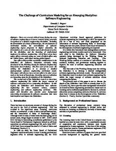
Figure 4 – Five-layer architecture To meet the external design specifications, they had to perform internal design, according to the process-recommended five-layer architecture (boundary, control, entity, persistence and system layers). Table 7 explains the meaning of the layers, and Figure 4 shows their dependency relationships. Generally, a class in one
Realizes
Test description (test specification) Design model (logical view) Source code
During these iterations, he students had to write specifications for functional tests, derived of and consistent with the external design specifications. For grading these, the instructor evaluated correct test execution, as well as test coverage, compared with the external design specification.
Table 8 shows the dependency relationships between the artifacts or artifact sections that are more significant from the course viewpoint; these dependencies form the basis for required consistency checking. Refining means providing a more detailed specification of something that has been specified at a coarser level of detail; realizing means providing the implementation for a specification element. Both terms conform to the UML definition, as stated in [16]. Must conform to
Project proposal
Project proposal standard
Requirements specification
Requirements specification standard
Analysis model Design description
Design model Test description
Test description standard
Test scripts Source code Executable code
Definition
Implemented FP
Total function points counted for the implemented use cases.
Implemented fraction
Implemented FP / Total FP
Effort per iteration
Total effort spent by a group in an iteration, in hours
Total effort
Total effort spent by a group in the project, in hours
Technical review, inspection
Effort per student
Total effort spent by a student in the project, in hours
Inspection
Specification effort per FP
Total effort spent by a group in the requirements and analysis, in hours, per total FP
Development effort per FP
Total effort spent by a group in the design, test and implementation, in hours, per implemented DF
Management effort per FP
Total effort spent by in the management workflows, in hours, per total FP
Total effort per FP
Sum of specification, development and management efforts, in hours, per FP
Productivity
Function-points per person-month (120 / Effort per FP)
Must pass
Technical review
Technical review, inspection Inspection
Coding standard
Result Total FP
Technical review Design description standard, user interface standard
Table 10 – Summary of experimental results Total function points for the whole product, as counted at the end of iteration 3.
Table 9 – Artifacts approval criteria Artifact
iteration reports passed the consistency analysis for ALL iterations.
Inspection Test script execution
Table 9 shows the criteria for artifacts approval. Grades were based on the success in passing these criteria. Technical reviews check mostly for documentation quality, while inspections check for content quality. Quality is understood as conformance both to process standards (as in Table 9) and to artifact dependencies (as in Table 8).
4. APPLICATION RESULTS 4.1 Collected results Table 10 shows the aggregate results collected for the experiments performed with two classes. For each result, the average and standard deviation were computed. The sizes of the whole project and of the implemented use cases are measured in function points. The implemented fraction shows how much of the specified functionality was actually implemented. The recorded effort, measured in work hours, was totaled per iteration and for the whole project. Normalizing the effort relatively to the project size and to the group size provides bases for comparison. Notice that the effort dedicated to the workflows related to specification and management was divided, by the total function points, whereas the effort dedicated to development related workflows was divided by the implemented function points.
4.2 First experiment Table 11 shows the collected results for the first class. These results consider the data supplied by the three groups whose
This class performed four iterations only. The reason was that the logical views of the analysis models delivered at the end of the second module were very poor, unlike the corresponding use case descriptions. This seemed to stem from a bias towards functional decomposition, caused by the background in structured analysis of most students. Some class time was spent in critiques of the analysis models, and these had to be resubmitted, thus prolonging the third iteration, leaving time enough for just one more iteration. 20% of the functionality was implemented, in the average. This matches a process guideline, which recommends having 20% of the functionality implemented at the end of the fourth iteration. This iteration is intended to test the chosen architecture, implementing the 20% top critical functionality. The students chose the use cases for this iteration after informal risk discussions with the instructor. The effort per student averaged 96 hours, spread through 135 elapsed days. This effort might be considered reasonable, given that only nights and weekends were available for homework; that time had to be spent in theoretical study; that the program had other courses; and that the students had to write a term paper by the end of the whole program. However, the following class proved that it was possible to increase the workload. The specification effort was somewhat low, compared to the development effort, even after rework of the analysis model.
Some groups had to perform a large amount of rework for their design and implementation; in their first attempt, they generally did not use correctly the mandated five-layer architecture, or performed disguised structured design and implementation. The recorded management effort was very low; apparently, the groups had different views on which tasks should be considered as “management”. We have often found that industrial trainees also show this particular difficulty. Table 11 - Results of the first experiment Average
Standard deviation
Total FP
126,6
18,6
Implemented FP
24,9
9,1
Implemented fraction
20%
8%
1
16,8
12,3
2
45,5
27,1
3
93,1
23,6
4
257,8
133,5
5
-
-
Total effort
413,3
167,5
Effort per student
96,0
41,9
Specification effort per FP
1,7
0,9
Development effort per FP
7,5
0,9
Management effort per FP
0,2
0,2
Total effort per FP
9,4
1,9
Productivity
13,2
3,0
Effort per iteration
The average productivity, about 13 function-points per personmonth, might be considered good for industrial standards; [5] considers as low a productivity measure below 5 functions-points per person-month. However, this must be considered as artificially high. In this experiment, all the tests were manual; therefore, the implemented use cases should not be considered as extensively tested. Indeed, it was observed that they tended to work correctly for well-behaved inputs, but, generally, were not robust enough, for invalid inputs. On the other hand, we have also observed that, in industrial settings, false high productivity is often claimed, because the products are delivered while still having significant quality problems. This is essentially the same problem.
4.3 Second experiment Table 12 shows the results for the second class. This class was instructed to perform much more thorough analysis than the first class. In addition, they were told to shift more analysis to the second iteration, in order to compute a rough estimate of the function points, and trim the project scope. They were able to complete much better requirements specification and analysis models by the end of iteration 3, and thus were able to
perform through iteration 5. This also led to the implementation of a larger fraction of the use cases. It can be seen that the average spent effort was 78% larger than in the case of the first class, but the elapsed duration was 177 days, only 31% larger. The students requested a few postponements of iteration ends, as had happened also with the first class, but there were no complaints about the workload being too heavy. Table 12 – Results of the second experiment Average
Standard deviation
Total FP
115,4
22,9
Implemented FP
42,7
15,0
Implemented fraction
37%
7%
1
12,7
3,1
2
116,3
65,9
3
128,3
57,0
4
220,3
58,6
5
260,0
109,2
Total effort
737,7
187,0
Effort per student
184,4
46,7
Specification effort per FP
2,5
1,8
Development effort per FP
11,4
5,5
Management effort per FP
0,4
0,3
Total effort per FP
14,3
6,4
Productivity
10,2
6,1
Effort per iteration
Automated tests were required for this class. The test scripts were written in Java itself, exercising the functionality provided by the control layer, since it would be more difficult to automate the test of the GUI classes of the boundary layer. The architecture required that all functional requirements were implemented in the control classes and below, leaving to the boundary classes just presentation matters. The performed inspections had to confirm that the tests covered the behaviors specified by the design-level use cases, and that these were consistent with the functional requirements, expressed by the analysis-level use cases. Probably, this was the single most important cause for the increase in the workload. The effort to write the test scripts was probably not very significant, since the process demanded written test specifications, whether their execution was manual or automatic, and the script code was quite straightforward. Now much more functional defects were caught by the tests. A larger effort had to be invested in fixing these defects, but the quality improved significantly, as the instructor was also able to verify by manual execution with random inputs. There also some fall in productivity, but this corresponded to a more acceptable quality level. We have also observed this behavior in process implementation in real organizations. The first productivity measurements seem surprisingly high, but many
defects show up later, since insufficient quality assurance allows delivery with a larger number of unfixed defects. On the other hands, since the automated tests bypassed the boundary layer, they were not able to detect presentation defects, such as enabling and visibility of interface elements. Manual testing by the instructor confirmed that a number of these defects remained.
5. CONCLUSIONS 5.1 Background summary We described a process-based approach to teaching software engineering. The following software engineering disciplines were taught as techniques for performing process workflows: requirements, analysis, design, tests, implementation, project management, quality management, and process engineering. The process used is iterative and object-oriented, blending elements from the Unified Process, the SW-CMM and the IEEE software standards. The students were required to specify an information technology application, and to implement completely some of its functions, modeled as use cases. Project success was measured not only by the functionality of the resulting implementation, but by the consistency and conformance to process standards of a set of artifacts. These include project proposal, requirements specification, analysis model, design description, design model, test plans and specifications, test reports, source and executable code, project plans and estimation spreadsheets, requirements databases, and reports of inspection and technical reviews.
5.2 Course projects results summary Two experiments were conducted, both with classes of students of an industry-oriented graduate program. These students had previous programming experience, but most of them used structured analysis, design, and programming, in their work environments. Each class had about 25 students, and these worked in teams of 3 to 5 persons. The applications had a size about 100 function points. The students wrote most of their artifacts in Microsoft Word and Excel; the analysis and design model were built with Rational Rose; and the mandatory implementation language was Java. The first class was able to perform four process iterations, while the second class reached five iterations. The second class had better performance. In the average, it was able to specify the whole project and implement 37% of the specified functionality. The average effort per student was about 180 work-hours, spread in circa 25 weeks. The average productivity was 10 function points per person-month. From the first to the second class there was an apparent fall in productivity, but the resulting products were much more robust. The two main factors for this improvement seemed to be an earlier and larger investment in the analysis model, and the use of automated tests. Overall, we confirmed our hypothesis that a process-based approach allows learning and practicing at least the highlights of many industrial software engineering techniques and practices, within quite limited schedule and time budget.
5.3 Future directions At the time of this writing, we conduct an experiment with a third class. This time the students are provided with a test framework, derived from the JUnit open-source framework, that allows unit tests at the level of the control and entity layers, as well as acceptance tests that exercise the boundary layer. In addition, the process has been streamlined to trim a number of manual transcription tasks. This is intended to impart more agility to the used process, without sacrificing its thoroughness and coverage of good practices. All design and test information is now contained in the design model, so that the students are no longer required to write design and test description documents. The design model has a structure that mirrors their respective IEEE document standards. Therefore, an automated document generator, such as Rational SODA, might extract these documents, if required by real-life contracts. As an additional improvement, the students now have access to an open, application-independent persistence layer. In the previous experiments, they had to code specific relational-to-object mappings for each persistent class.
6. ACKNOWLEDGMENTS We thank IBM Rational for the license to use the Rational Suite Enterprise, within the SEED program (Software Engineering for Educational Development).
7. REFERENCES [1] Boehm, B. A Spiral Model of Software Development and Enhancement, in Proceedings of the International Workshop Software Process and Software Environments, ACM Press, 1985.
[2] Boehm, B., and Egyed, A. Improving the Life-Cycle Process in Software Engineering Education, in Proceedings of the European Software Day (as part of the 24th Euromicro conference), 1998.
[3] Boehm, B., Egyed, A., Port, D., Shah, A., Kwan, J., and Madachy, R. A Stakeholder Win-Win Approach to Software Engineering Education. Annals of Software Engineering Software Engineering Education, Volume 6, Issue 1-4, Kluwer Academic Publishers, 1998, 295-321.
[4] Boehm, B., and Port, D. Conceptual Modeling Challenges for Model-Based Architecting and Software Engineering (MBASE), in Chen, P., Akoka, J., Kangassalo, H., and Thalheim, B. (eds.). Conceptual Modeling: Current Issues and Future Directions. Lecture Notes in Computer Science. Vol. 1565, Springer Verlag, Heidelberg, 1999.
[5] Jones, C. Assessment and Control of Software Risks. Yourdon Press – Prentice-Hall, Upper Saddle River – NJ, 1994.
[6] Humphrey, W. S. A Discipline for Software Engineering. Addison-Wesley, Reading MA, 1995.
[7] Humphrey, W. S. Introduction to the Team Software Process. Addison-Wesley, Reading - MA, 1999.
[8] IEEE, IEEE Standards Collection - Software Engineering. IEEE, New York – NY, 1994.
[9] Jacobson, I., Rumbaugh, J., and Booch, G. Unified Software Development Process. Addison-Wesley, Reading – MA, 1999.
[10] Kruchten, Ph. Rational Unified Process: An Introduction. Addison-Wesley, Reading – MA, 2000
[11] Longstreet, D. Function Points Analysis Training Course. http://www.SoftwareMetrics.com , Mar. 2002.
[12] OMG. Software Process Engineering Metamodel Specification. Version 1.0, http://www.omg.org, Oct. 2002.
[13] Paula Filho, W. P. Requirements for an Educational Software Development Process, in Proceedings of. The 6th Annual Conference on Innovation and Technology in Computer Science Education, Canterbury – UK, Jun. 2001, pp. 65-68.
[14] Paula Filho, W. P. Engenharia de Software: Fundamentos, Métodos e Padrões, 2nd. ed. LTC Editora, Rio de Janeiro – Brazil, 2003 (in Portuguese).
[15] Paulk, M. C., Weber, Ch. V., Curtiss, B., and Chrissis, M. B. The Capability Maturity Model: Guidelines for Improving the Software Process. Addison-Wesley, Reading – MA, 1995.
[16] Rumbaugh, J., Jacobson, I., and Booch, G. Unified Modeling Language Reference Manual. Addison-Wesley, Reading – MA, 1999.