A Process-Tolerant Cache Architecture for Improved Yield ... - CiteSeerX
Recommend Documents
Stacking a high-density DRAM die on processor cores makes it possible to implement a large last level cache with high on-chip memory bandwidth [1][2][3].
We simulate 75.000 particles, i.e. a working set of 4 Mbyte. MP3D-DIFF is a rewritten version of the program, where a better hit rate is achieved. The distribution ...
Frank Vahid*and Walid Najjar ...... [10] J. L. Hennessy and D .A. Patterson, âComputer architecture ... [15] J. Kin, M. Gupta and W. Mangione-Smith, âThe Filter.
Dec 3, 2009 - Send comments regarding this burden estimate or any other aspect of this collection of information, including suggestions for reducing this ...
Mar 29, 2002 - be able to rely on tools and/or monitoring techniques, which al- ... type of a hardware monitoring facility with the same positive properties ...
(UMA). The contention for the common memory and the common bus limits the ... memory architecture (UMA), (b) nonuniform memory architecture (NUMA),.
department of New Mexico State University, Las Cruces, NM. Email:{misra, rtourani}@cs.nmsu.edu. A. Related Work ..... My(u, j) = (1â fy (u,j). maxxeе1U{n}.
season and in-season crop growth (Stephens and Lyons 1998; Hill and Donald 2003). The typical sandy soil types have a very limited water storage capacity, ...
proved Fallahpour Audio Watermarking Scheme is proposed, demon- strating the suitability of ... of watermarking techniques allows to add an imperceptible and statistically undetectable signature to ... and online audio-clips trade. FPGAs are ...
Oct 31, 1996 - The newsgroups of the \Wirt- ...... Benjamin Cummings, second edition, 1994. CS]. Geo rey. Collyer and. Henry. Spencer. ... William Stallings.
its dedicated news server which is the client's access point to the News infrastructure. Each news server then keeps a copy of this article and propagates it to its ...
for designers, assisted in part by recent computer-aided design (CAD) tuning ... Additional Key Words and Phrases: Cache, configurable, architecture tuning, low ...
filter and analyze the value of counters in the counting Bloom filters. Afterwards, we introduce a new cache architecture called the cached counting Bloom filter ...
Web (WWW) and electronic mail as a synonym for the In- ternet. While WWW is excellent .... is batch-oriented and does not support on-demand connec- tions like HTTP. .... cause the sender of all articles has to be verified [17]. 4.4 Compressed ...
the distributed caching scheme in the majority of .... HTML documents will use the same inline image ..... is no cached copy of the requested object and thus.
cache ways that cause delay violation and/or have excessive leakage. We also ... microprocessor, which does not meet a frequency constraint .... combining the advantages of both schemes, the Hybrid scheme ..... They also nullify the losses.
violation that may occur if it is ignored. ... provided in the AADL behavior annex [9]. These ..... If these modules are described as finite-state machines in the AADL.
Mar 16, 2011 - supervision, advice, and guidance from the very early stage of this research as well as ... Wit and Dr. Mario Diaz Nava, for their commitment to take part in my jury committee. ... I owe her for being unselfishly let her intelligence,.
QUALCOMM Incorporated. 2. The University of Texas at Austin. ABSTRACT. A novel circuit approach to increase SRAM Static. Noise Margin (SNM) and enable ...
Documenting Software Architectures: Views and Beyond. Addison Wesley, 2003. [5] Mary Shaw, Hans Van Vliet,Software Architecture Education Session Report ...
results in an industry-standard HTTP proxy/caching server called Squid. .... Last-Modified header in the saved item, Squid adds an If-Modified-Since header to ...
architectures, with multiple multi-core CPUs, integrated memory controllers ..... the same CPU cache, as accessing the cache is much faster than going to the ...
results in an industry-standard HTTP proxy/caching server called Squid. One of the ... Previously, this was managed in Frontier by separating queries into two types: (1) .... Instead of including the full data payload, the response is a very small.
Jun 24, 2009 - in a cache hierarchy can be made of disparate memory tech- nologies; and intra cache level or cache Region based HCA. (RHCA), where a ...
A Process-Tolerant Cache Architecture for Improved Yield ... - CiteSeerX
significantly high in a sub-50-nm technology regime, which can severely affect the yield, ... The authors are with the School of Electrical and Computer Engi- neering ...... fall 2003, He was with Intel circuit research lab, Hillsboro working on high.
IEEE TRANSACTIONS ON VERY LARGE SCALE INTEGRATION (VLSI) SYSTEMS, VOL. 13, NO. 1, JANUARY 2005
27
A Process-Tolerant Cache Architecture for Improved Yield in Nanoscale Technologies Amit Agarwal, Student Member, IEEE, Bipul C. Paul, Member, IEEE, Hamid Mahmoodi, Student Member, IEEE, Animesh Datta, Student Member, IEEE, and Kaushik Roy, Fellow, IEEE
Abstract—Process parameter variations are expected to be significantly high in a sub-50-nm technology regime, which can severely affect the yield, unless very conservative design techniques are employed. The parameter variations are random in nature and are expected to be more pronounced in minimum geometry transistors commonly used in memories such as SRAM. Consequently, a large number of cells in a memory are expected to be faulty due to variations in different process parameters. In this paper, we analyze the impact of process variation on the different failure mechanisms in SRAM cells. We also propose a process-tolerant cache architecture suitable for high-performance memory. This technique dynamically detects and replaces faulty cells by dynamically resizing the cache. It surpasses all the contemporary fault tolerant schemes such as row/column redundancy and error-correcting code (ECC) in handling failures due to process variation. Experimental results on a 64-K direct map L1 cache show that the proposed technique can achieve 94% yield compared to its original 33% yield (standard cache) in a 45-nm predictive technology under inter = intra = 30 mV. Index Terms—Process-tolerant cache, resizing, SRAM failures, yield.
I. INTRODUCTION
S
CALING of CMOS devices has provided remarkable improvement in performance of electronic circuits in the last two decades. However, as silicon industry is moving toward the end of the technology roadmap, controlling the variation in device parameters during fabrication is becoming a great challenge. The variations in process parameter such as the channel length, width, oxide thickness, and placement of dopants in a channel result in a large variation in threshold voltage [1]. Among them, the random placement of dopants is more of a concern [2] because it is independent of transistor spatial locations and causes threshold voltage mismatch between the transistors, which are close to each other (intra-die variation). These atomic-level intrinsic fluctuations cannot be eliminated by external control of the manufacturing process and are expected to severely affect the minimum-geometry transistors commonly used in area-constrained circuits such as SRAM cells.
Manuscript received September 22, 2003; revised April 28, 2004. This work was supported by the Defense Advanced Research Projects Agency (DARPA), MARCO, GSRC, SRC, and by Intel and IBM. The authors are with the School of Electrical and Computer Engineering, Purdue University, West Lafayette, IN 47907-1285 USA (e-mail: [email protected]; [email protected]; [email protected]; [email protected]; [email protected]). Digital Object Identifier 10.1109/TVLSI.2004.840407
A major part of any electronic system is the memory subsystem. State-of-the-art microprocessor designs devote a large fraction of the chip area to memory structures, e.g., multiple levels of instruction and data caches, translation look-aside buffers, and prediction tables. For instance, 30% of Alpha 21 264 and 60% of StrongARM are devoted to cache and memory structures [3]. Since memory is one of the biggest blocks of any system, it is more prone to faults under process variation. A failure in memory cell can occur due to 1) an increase in cell access time and 2) unstable read/write operation [4]. The mismatch in device parameters will increase the probability of these failures. Hence, a proper failure analysis is necessary to understand the impact of process variation on different fault mechanisms. Conventionally redundant rows/columns [5], [6] are used to replace faulty rows/columns, to improve yield in memories. These redundancy techniques either have performance overhead or have limitations on the number of faulty rows/columns it can handle, due to resource limitation and design complexity. In particular, the failures due to random dopant effect are randomly distributed across the dies, resulting in a large number of faulty rows/columns. Recovery from such defects cannot be handled by row/column redundancy. We will show that, with the drastic increase in parameter variation, redundancy alone will not result in good yield. Moreover, the number and the location of failures due to process variation changes depending on operating condition (e.g., supply voltage and frequency), which cannot be handled by any static technique such as row/column redundancy. Error correcting code (ECC) [7], [8] employed in existing design to correct transient faults (soft error), can also be used to correct failures due to process variation. However, ECC can correct only a single-error, and hence, will not be sufficient in tolerating a number of failures due to process variation. In this paper, we analyze the effect of process variation on different failure mechanisms in SRAM cell. Based on this analysis we estimate the expected yield of a 64-K L1 cache in BPTM 45-nm technology [9]. We propose a process-tolerant cache architecture suitable for high-performance memories, to detect and replace faulty cells by adaptively resizing the cache. This architecture assumes that the cache is equipped with an online built-in-self-test (BIST) [10], [11] to detect faulty cells due to process variation. The proposed scheme then downsizes the cache by forcing the column MUX to select a nonfaulty block in the same row if the accessed block is faulty. This architecture has a high-fault tolerant capability compared to contemporary fault
IEEE TRANSACTIONS ON VERY LARGE SCALE INTEGRATION (VLSI) SYSTEMS, VOL. 13, NO. 1, JANUARY 2005
tolerant techniques, with minimum energy overhead and does not impose any cache access time penalty. This scheme maps the whole memory address space into the resized cache in such a way that resizing is transparent to the processor. Hence, the processor accesses the resized cache with the same address as in a conventional architecture. We evaluate the performance of this architecture both analytically and experimentally. We also compared our technique with conventional fault tolerant techniques such as redundancy and ECC. The rest of the paper is organized as follows. In Section II we analyze different failure mechanisms in an SRAM cell due to process variation. Section III explains the basic cache architecture. In Section IV, we explain the proposed process-tolerant cache architecture and describe the implementation of different circuit blocks required by this scheme. Section V presents the analysis and combines it with experimental results to compare the fault tolerant capability and resulting yield of the proposed scheme with ECC and redundancy. In Section VI we draw our conclusions. II. FAILURE ANALYSIS OF SRAM CELL DUE TO PROCESS VARIATION A failure in a SRAM cell can occur due to 1) an increase in the access time of the cell (access time failure) and 2) destructive read (read failure) and/or unsuccessful write (write failure). In a die, failures are principally caused by the mismatch in the device parameters (length, width, and transistor threshold voltage) of different transistors (intra-die) in the cell. Such device mismatch modifies the strength of the different transistors resulting in different failure events. The primary source of device mismatch is the intrinsic fluctuation of the of different transistors due to random dopant effect [2]. Hence, in this paper we have considered the variation as the major source of intra-die variation while analyzing the failure probabilities. One should note that the effect of other parameter variation can be translated into the effective variation in threshold voltage. A. Access Time Failure (AF) The cell access time is defined as the time ) required to produce a prespecified (say, voltage difference between two bit-lines (bit-differential). For ` ' and ` ' (Fig. 1), bitline BR will a cell storing discharge through transistors AXR and NR during the read is a strong function of of AXR operation. Hence, of these transistors and NR. Therefore, any variation in changes and will cause an access time failure if it is . greater than the maximum tolerable limit B. Read Stability Failure (RF) (Fig. 1) increases due to the During the read operation, voltage divider action of AXR and NR to a positive value . If is higher than the trip point of the inverter PL-NL then the cell flips [Fig. 2(a)] resulting in a depends on the of AXR and NR, while read failure. is a function of the of PL and NL. Intrinsic variation of these transistors can change both and in leading to a read failure.
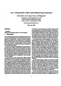
Fig. 1. Schematic of an SRAM cell.
C. Write Stability Failure While writing a ‘0’ to a cell storing ‘1’, the node (Fig. 1) gets discharged through BL to a low value determined can not by the voltage division between the PL and AXL. If , be reduced below the trip point of the inverter PR-NR , then a write within the time when word-line is high failure occurs [Fig. 2(b)]. Variation in of PL, AXL, PR, and NR can cause a write failure. It should also be noted that the failure mechanisms described above are functions of supply voltage and frequency of operation, and hence, the failure map of a cache will change if the operation conditions are altered. D. Probability of Failure Intrinsic variation in nanoscale technology is random in nature. Hence, in order to analyze the probability of failure, the threshold voltage of all six transistors in a cell are considered as six independent random variables and assumed to have a of the Gaussian distribution. The standard deviation variation depends on the manufacturing process, doping profile, and the transistor size. Fig. 3 shows the result of Monte Carlo simulations for the probability of different failure mechanisms, . The using the BPTM 45-nm technology, for different probability of a failure is calculated as the ratio of the number of occurrence of a particular failure to the total number of experiments. It can be seen from the figure that the probability of all three-failure mechanisms increases considerably , however, it is mostly dominated with process variation is by access time failures. In 45-nm technology, where expected to be 30 mV [12], effective probability of failure can be as high as (Fig. 3). This indicates that there will be a large number of faulty cells in nanoscale SRAMs under process variation, affecting the yield. E. Yield Analysis of a 64 K-Cache Under Process Variation In order to analyze the yield of a cache under process variation, we considered both inter-die and intra-die variation. Intra-die variations are the variations in device parameters within a single chip, which means different devices at different locations on a single die may have different device features. Inter-chip variations, on the other hand, are the variations that occur from one die to the other, from wafer to wafer, and from wafer lot to wafer lot. We first model inter-die variation of as a Gaussian distribution [13] and use the probability density function (pdf) of this distribution as the mean of intra-die variation. Hence, different dies will have different (due to
AGARWAL et al.: A PROCESS-TOLERANT CACHE ARCHITECTURE FOR IMPROVED YIELD IN NS TECHNOLOGIES
inter-die variation) for intra-die variation. Based on and the probability of failure in a particular die is obtained through Monte Carlo simulation (as explained in the previous section). The number of faulty cells in a die, thus, can be calculated as (1) is the total number of cells in a cache. where We simulated 1000 chips (64 Kcache) in 0.9 V, 45 nm BPTM V having technology with nominal mV [12]. Fig. 4 shows the number of chips with different number of faulty cells in a 64 K-cache. Out of 1000 chips, only 334 chips are expected to be fault free, resulting in a 33.4% yield. This suggests the need for process/fault-tolerant mechanisms to improve the yield in memory. The following sections describe our proposed process-tolerant memory architecture to improve the yield of nanoscale caches. III. BASIC CACHE ARCHITECTURE Before we discuss the proposed architecture, we first describe general cache architecture and define terms related to the cache design. We take an example of a 64 kB direct mapped L1 cache to explain the different parameters associated with a cache. In this paper we focus on direct map cache, however, our design is applicable to both direct and set associative caches. Fig. 5 shows the block diagram of a 64 K cache macro [8], [14], [15]. Cache core is divided into two arrays; data and tag arrays. Data and tag arrays are further divided into blocks. The size of the data block is the number of data bytes accessed per cache access (e.g., 32-B data per cache block). In a 64-K cache,
typically 2-K blocks (4 blocks in a row) with 32-B block size are arranged in 512 rows. The cache address is divided into three parts; tag, index, and byte offset. The number of index bits depends on the cache and the block size. It is the number of bits needed to decode a single block in cache. Byte offset is the address of a byte in a data block. The rest of the address bits are tag bits. Since cache size is small compared to the main memory, only a part (index) of the memory address is required to access the cache. Therefore, more than one memory addresses are mapped to a single cache block. To distinguish among these memory addresses, extra bits (tag bits) associated with the memory address are stored into tag array during cache WRITE. Tag array is organized and accessed in a similar way as the data array. Based on index bits both data and tag are accessed in parallel. Multiple blocks are stored in a single row in order to reduce area overhead and routing complexity and are selected simultaneously. Depending on the number of blocks in a row, index is further divided into row address and column address (Fig. 5). The row address selects a single row from both data and tag arrays, which places the data (all blocks in the row) into bit-lines. The column address then selects one block (both data and tag) through column MUX. Sense amplifiers sense the data and restore the logic level. The accessed tag is then compared with the address tag and a cache hit/miss occurs. In case of a hit, byte offset selects a final word from the accessed block. Data output drivers send this word to CPU. In case of a miss, a lower level of memory hierarchy is accessed. IV. PROCESS-TOLERANT CACHE ARCHITECTURE In this section, we explain the proposed process-tolerant cache architecture. We describe the cache resizing scheme that avoids faulty cells to improve yield. Finally, we describe various schemes to implement the extra circuit blocks needed to store the fault locations. A. Proposed Architecture Fig. 6 shows the anatomy of the proposed cache architecture. The architecture assumes that the cache is equipped with a BIST circuitry, which tests the entire cache and detects faulty cells based on the failure mechanisms described in Section II. Any conventional BIST [10], [11] can be employed to perform
30
IEEE TRANSACTIONS ON VERY LARGE SCALE INTEGRATION (VLSI) SYSTEMS, VOL. 13, NO. 1, JANUARY 2005
Fig. 4. Fault statistics of a 64-K cache in BPTM 45-nm technology.
Fig. 5. Block diagram of a 64-K cache macro.
single cell in a block is faulty. BIST detects the faulty blocks and feeds this information into a configurator. Based on the number of faults and their locations, the configurator decides whether the chip can work for a given operating condition and generate a faulty/nonfaulty signal. The configurator stores the fault information in config storage. Stored information of faults for a particular operating condition is saved from the config storage to hard disk, whenever the processor is turned off. At the time of rebooting, the processor by default reloads the old fault information from hard disk to config storage. If there is any change in the operating condition, the test mode signal is turned on and new fault information is stored in config storage. The fault information stored in config storage is used to resize the cache to avoid faulty blocks during regular operations of the circuit. B. Resizing the Cache Fig. 6.
Architecture of a 64-K process-tolerant cache.
these tests. Since the number of faulty cells and their location changes depending on operating condition (e.g., supply voltage, frequency), such tests are conducted whenever there is a change in operating condition. As described in Section III, a cache is divided into cache blocks. Each block is tested using BIST when the test mode signal is on. A block is considered faulty even if a
Conventionally, multiple cache blocks are stored in a single row and are selected simultaneously by a single word-line [8]. Finally, column MUX chooses one block based on column address. The key idea of the proposed architecture is to force the column MUX to select another block in the same row, if the accessed block is faulty. As described in the previous section, config storage stores the information about faulty blocks. In proposed architecture, both the cache and config storage are accessed in parallel. The fault information is fetched from config
AGARWAL et al.: A PROCESS-TOLERANT CACHE ARCHITECTURE FOR IMPROVED YIELD IN NS TECHNOLOGIES
Fig. 7.
31
Resizing the cache.
storage and fed to the controller before the column MUX selects a particular block. If the accessed block is faulty, the controller forces the column MUX to select another block in the same row by altering column address (Fig. 7). The selection of block from the set of nonfaulty ones is predefined (Section IV-D). Similarly, the tag array is also forced to select the corresponding block. Hence, any faulty block in the cache is replaced by an existing nonfaulty block, thereby downsizing the cache. Since, the proposed scheme reduces the cache size at block-level granularity, it can handle large number of faults without significantly reducing the cache size. C. Mapping Issue The conventional cache is accessed by a fixed number of index bits, which represents a unique block in the cache. The tag is stored and compared to distinguish among addresses having the same index bits. However, in the proposed architecture, a single block is accessed for more than one index in case of a faulty block. This may result in accessing the wrong data. Consider two memory addresses, which access two different blocks in the same cache row. Both of them will have the same row address with different column addresses. Let us consider that both of them have the same tag. Now, let us assume that the block corresponding to the address “one” is faulty and the controller forces the column MUX to select the block corresponding to the address “two.” Fig. 8(a) shows an example of this scenario. The block accessed by column address “00” is faulty and is mapped to column address “01” by the controller. Now consider the following piece of code: STORE D “one” LOAD “two” Register Since the block corresponding to location “one” is faulty, controller forces STORE to write data D and the corresponding tag T at location “two.” Now LOAD accesses the data and tag from address “two.” Since both addresses have the same tag, tag comparison results in a cache hit. However, data stored at location “two” is data related to address “one.” Hence, the processor receives wrong data. However, in the case of a conventional cache (having no faults) both LOAD and STORE access two different locations and this conflict does not occur. To deal with this situation, we maintain more number of tag bits than the conventional cache. We include column address bits into tag bits, which increases the size of tag array by a small
Fig. 8. Resizing of cache based on the fault location. (a) Mapping problem. (b) Extending tag bits. (c) Resolving the mapping problem.
amount, e.g., two extra bits are added to the tag in a cache having 4 blocks in a row [Fig. 8(b)]. The cache is accessed with the same number of index bits as before. Now, in the case discussed above, STORE to address “one” is forced by the controller to store the larger tag bits (“T 00”) to the tag array and D to the data array at location “two” [Fig. 8(c)]. The LOAD access to the address “two” compares the new tag which is different for address “one” and “two” resulting in a cache miss and the data is read from a lower level cache or main memory. In contrast, if there is a write (STORE) access (instead of LOAD) to location “two,” it is overwritten by the new data and the corresponding tag is stored. Since all tag bits are accessed and compared in parallel, adding extra bits do not add to the access time of the cache. This mapping technique allows the processor to access the cache without having the knowledge that the cache has been resized. Hence, the processor accesses the resized cache with the same address as in a conventional architecture. The fault tolerant capability of the proposed scheme depends on the number of blocks in a single row. The controller can alter the column address to select any block in a row. It can also select only one block for any access to that row, if all other blocks are faulty. As long as there is one nonfaulty block in each row, our scheme can correct any number of faults. Using this scheme (N blocks per row) of its cache can be downsized up to designed size. D. Config Storage One of the important blocks in the proposed scheme is the config storage. It stores the fault information and is read along with the cache on every read/write operation. Config storage should be fast enough to provide the fault information to the controller before the data reaches column MUX. Since config
32
IEEE TRANSACTIONS ON VERY LARGE SCALE INTEGRATION (VLSI) SYSTEMS, VOL. 13, NO. 1, JANUARY 2005
Fig. 9.
Config Storage. (a) CAM, an example to store 100 faults, (b) OBI.
storage is accessed every cache access, energy consumed in config storage should also be negligible compared to the energy consumed in the cache. At the same time, the config storage should be large enough to cover most of the faults to achieve high-fault tolerant capability. Based on theses constraints, two types of config storage are implemented:
COMPARISON
OF
TABLE I ENERGY AND PERFORMANCE BETWEEN DIFFERENT CONFIG STORAGE
1) content addressable memory (CAM) implementation; 2) one-bit implementation (OBI). The following section explains each scheme in detail and discusses pros and cons associated with each. 1) CAM Implementation: In this design, fault locations (index bits) are stored into a CAM [16]. The fault locations are written into the CAM at the time of testing. The size of CAM depends on the maximum number of faults that can be tolerated. The size can be decided based on the average number of expected faulty blocks due to the process variation in a cache for a particular technology. Along with the location of each faulty block, CAM also stores the column address of a nonfaulty block. This nonfaulty block is determined by the configurator at the time of testing, and the faulty block is mapped to this block whenever accessed. CAM is accessed in parallel with the cache using the index bits of the memory address. These index bits are compared with all the fault locations stored in the CAM. Since all the stored locations are compared in parallel, these comparisons are fast. Each comparison generates their local match signals [Fig. 9(a)]. These local signals are combined together using a domino OR to generate the final match signal. The controller uses this signal to decide whether to change the present column address. If there is a match, only one among all local match signals will be “1.” The corresponding column address stored in the CAM is then sent to the controller through a MUX. The controller then replaces the column address by the one read from the CAM. The energy overhead associated with the CAM depends on whether a match occurs or not. Since, the number of faulty blocks is expected to be small, the most common case is a no-match. To reduce the energy overhead, the CAM is designed using XNOR and dynamic AND gates that switches only if there is a match, resulting in less power consumption in case of a no-match.
To evaluate this scheme, a 64-KB cache is designed using the TSMC 0.25- technology. This cache has 2-K blocks with 32-B block size, arranged in 512 rows. Table I shows the energy and the delay from the row decoder to column MUX in a 64-kB cache. Table I also shows the energy overhead and the delay associated with CAM, designed to store 100–200 fault locations, respectively. It can be observed that energy overhead is negligible (2%–4%) compared to the dynamic energy per cache access. The time required to access the CAM is also much smaller than the row address to the MUX delay of the cache. This ensures that the appropriate column address arrives before data reaches column MUX and, hence, the latency to access the cache remains the same as a conventional cache. The energy overhead and delay depends on the size of the CAM. Hence, one has to consider the fault tolerance versus energy dissipation/area trade-off. For example, using a 100 entry CAM, one can tolerate up to 5% faulty blocks with only 0.25% area overhead in a 64-K cache. 2) OBI: In this design style, one bit per cache block is maintained in a small memory (OBI) to store the fault information. The bit is “1” if the corresponding block in the cache is fauty; otherwise, it is “0.” These bits are determined at the time of testing and stored in OBI by the configurator. Architecture of OBI is exactly the same as cache [Fig. 9(b)]. A block size of OBI is equal to the number of blocks in a cache row. Therefore, each block in OBI stores the fault information of all the blocks in a cache row.
AGARWAL et al.: A PROCESS-TOLERANT CACHE ARCHITECTURE FOR IMPROVED YIELD IN NS TECHNOLOGIES
TABLE II COLUMN ADDRESS SELECTION BASED ON FAULT LOCATION
OBI is accessed in parallel with the cache using the row address part of the index bits. It selects the OBI block corresponding to the cache row that is being accessed. This OBI block contains the fault information bit for all the blocks in the cache row. The bit corresponding to the accessed cache block is checked by the controller to determine whether it is faulty or not. If it is a “1,” the controller alters the column address to select a nonfaulty block based on the remaining bits read from the OBI. Table II shows an example of selecting proper a column address, based on the fault information from the OBI, in a cache having 4 blocks in a row. In case of a faulty block access, this scheme selects the first available nonfaulty block. For example, if the third block is faulty (Table I) the controller replaces it with the first block. In case of two faulty blocks in a row, it replaces the first available nonfaulty block with the first faulty block and the second available nonfaulty block with the second faulty block to minimize the number of blocks mapped to the same location (Table I). In case of three faulty blocks in a row, it selects the nonfaulty block irrespective of which block is accessed. If all four blocks in a row are faulty, then the memory cannot be used. Hence, as long as there is one nonfaulty block in each row this architecture can correct any number of faults. In a 64-K cache, 2 K blocks are arranged in 512 rows, each row contains four blocks. This configuration requires a 2-K b OBI with 4-b block size [Fig. 9(b)]. To optimize the access time, OBI is designed with aspect ratio of 1. It is arranged in 32 rows and each row contains 64 cells (16 OBI blocks). Table II shows the delay and energy overhead associated with the OBI. An access delay of a 2-K b OBI is more than 100 or 200 entry CAM, but it is still less (almost half) compared to row decoder to MUX delay of a 64-K cache. Hence, using the OBI as config storage does not pose any latency overhead in the proposed architecture. Energy overhead in accessing the OBI is also negligible compared to the dynamic energy per cache access. The size and the design of OBI are independent of the number of faulty blocks in a cache. In a best case using the OBI, this architecture can handle up to 75% faulty blocks with 0.5% area overhead. The choice between a CAM and OBI depends on the following factors (depending on the technology): • • • •
row decoder to MUX delay of the cache; expected number of faulty blocks; energy overhead; area penalty.
33
For a technology in which the expected number of faulty blocks are small, the CAM might be a good choice since it is fast and requires a less number of extra bits compared to OBI. The number of extra bits is important because any fault in these bits might reduce the overall yield. If the expected number of faulty blocks is high, a large CAM will be needed, which may have high-energy overhead and area penalty. In such a case, OBI would be the good choice since it can handle up to 75% faulty blocks with very small energy and area overhead (irrespective of number of faulty blocks). Since, this architecture is proposed for future technologies, which may have a large number of faulty blocks due to a process variation, we consider OBI as our choice of config storage. V. RESULTS AND DISCUSSION In this section, we present experimental and analytical results on yield improvement under process variation in the proposed cache architecture and compare it with existing techniques. In this analysis, we only consider the cell failures due to process variation as described in Section II. First, we describe our analytical model for probability of having an operational chip and effective yield using different fault tolerant schemes (redundancy, ECC, and the proposed architecture). Second, we show the results based on an analysis of a 64-K cache employing different fault tolerant schemes. We combine different schemes and select best possible combinations having best fault tolerance with minimal area and power overhead. Finally, we evaluate each combination by combining analysis with our experimental data to calculate the final yield. We also analyzed the effect of resizing on CPU performance for high-performance microprocessors. A. Analytical Model for Yield For a cache with no built-in fault tolerant mechanism, only the completely fault free working dies are acceptable. However, employing fault tolerant schemes, one can salvage dies that have a finite number of faults distributed in a certain way. Each fault tolerant scheme has its own limitations in terms of the number of faults and their distribution that it can handle, e.g., ECC can only correct one faulty bit per block. Hence, the probability of having an operational chip using a fault tolerant scheme varies depending on number of faulty cells and is defined as follows. their locations. is the probability that a chip with Definition 1: can be made operational using any fault tolerant schemes. Since the primary source of cell failures in this analysis is due to the random placement of dopant, to determine , we assume that faults are randomly distributed across the die. , we calculate the probability that a chip Based on can be corrected using available resources [17]. Each scheme adds some spare blocks, which in turn can be faulty. Hence, the probability of having faults in these blocks should also be considered in calculating the final probability. The final yield, , which is defined as the ratio of the number of working chips to the total number of fabricated chips, can be calculated , by multiplying it by the number of from
34
IEEE TRANSACTIONS ON VERY LARGE SCALE INTEGRATION (VLSI) SYSTEMS, VOL. 13, NO. 1, JANUARY 2005
chips
with and summing over all possible in our simulation
TABLE III CONFIGURATION OF A 64-K CACHE WITH DIFFERENT FAULT-TOLERANT SCHEMES
(2) However, adding a spare block increases the chip area and reduces the number of chips that fits into the wafer area. Consequently, a better measure for evaluating the benefit of each scheme is effective yield, defined as (3) In our analysis, we have ignored the area overhead associated with extra control circuitry, fuses, and routing. We only consider the area overhead due to extra storage space. To describe our model, we assume a cache having M rows. Each row contains N cache blocks and the size of each block is B bits. are randomly distributed inside the memory. To simplify our description we only consider data array in our analysis and ignore the tag array. However, our final results do include tag array in the analysis. Considering tag array requires a simple extension of the model described below by either adding the number of tag bits into block size (for the proposed architecture) or considering the tag as a separate block (for ECC and redundancy). 1) Redundancy: Redundancy schemes replace faulty rows/columns with redundant rows/columns. For simplifying our expressions, we represent both row and column redundancy with redundancy is defined as in terms of redundant rows. the probability that the number of faulty rows in a chip is less than or equal to the number of redundant rows. Let us assume that there are R redundant rows. Hence, for a good chip, among rows, at most R rows can be faulty. is the probability that exactly out of Definition 2: rows are faulty. To calculate the we first calculate the probability of bits) is considered faulty if it having a faulty row. A row ( has at least one faulty bit. Since faults are randomly distributed , which depends on with the fault probability, (1), probability of having one row faulty is given by (4)
due to the high area and delay penalty associated with it [18]. We number assume that cache maintains of ECC bits per cache block and can correct only one fault in with a block, where B is the number of bits in each block. ECC is defined as the probability that every block in a cache has blocks in the cache. at most one faulty bit. There are Hence, the probability of having an operational chip using ECC is given by
(8) (9) 3) Proposed Architecture: Using OBI as config storage, the proposed scheme can correct any number of faults as long as with resizing at least one block in every row is nonfaulty. is defined as the probability that each row has at least one nonfaulty block and config storage is fault free. A block is considered faulty even if only one bit in that block is faulty. The probability of a block to be faulty is given by (10) Hence, the probability of having a row that can be corrected (i.e., there is at least one nonfaulty block in a row having N blocks), is given by
and thus
(11) and the probability that all M rows can be corrected is (5)
(12)
(6)
There are blocks in the cache and hence, the size of the OBI is bits. Therefore, the probability that OBI is fault free is given by
Hence, the probability of having an operational chip is
(13) (7) Here, is given by (2) and is the probability rows. that rows are faulty among 2) ECC: It has been shown that ECC with more than one fault correction capability cannot be implemented in memories
and thus (14) (15)
AGARWAL et al.: A PROCESS-TOLERANT CACHE ARCHITECTURE FOR IMPROVED YIELD IN NS TECHNOLOGIES
35
Fig. 10. Probability of salvaging a chip versus fault probability for a 64-K cache. (a) Proposed architecture, ECC, and redundancy. (b) Proposed architecture with redundancy in OBI. (c) Proposed architecture with redundancy in cache. (d) ECC with redundancy.
B. Yield Using Different Schemes for a 64-K Cache Table III shows the configuration of a 64-K cache with three versus different fault tolerant schemes. Fig. 10 shows the by employing different fault tolerant schemes. It can be observed from Fig. 10(a) that our proposed technique is more efficient in correcting faults compared to ECC or redundancy. It can correct 66% chips having 105 faulty cells, while ECC can only correct 6%, and it is impossible to correct any using row/column redundancy. The effective yield is calis obtained from the experimental reculated using (3). sults on the failure analysis described in Section II ( mV, nm BPTM, Fig. 2). The effective yield is plotted in Fig. 11. Without the use of ECC or resizing, using redundant rows only, results in maximum yield of 34% (for ), which is close to nominal yield [Fig. 11(b)]. Increasing the number of redundant rows/columns does not improve yield because the improvement in yield is masked by area overhead. Fig. 11(b) shows that ECC, without any additional redundancy , results in 46% yield. However, it is smaller compared to the yield using the proposed technique, which is around 69% [Fig. 11(a)]. can further be improved by adding an optimum number of redundant row/column along with ECC or the proposed
architecture. Yield of cache using the proposed scheme is a strong function of the probability that the config storage is not faulty. This is because each and every bit of config storage needs to be nonfaulty to ensure proper operation. Hence, to increase this probability, redundant rows (r) are added to OBI with a small increase in the area. The probability of a nonfaulty OBI is calculated in a similar way as cache using redundancy is determined using (14). Fig. 10(b) shows (Section V-A1). the effect of adding redundant rows to OBI on . Adding . The resulting yield redundant OBI rows greatly improves changes from 69% to a maximum of 86% [Fig. 11(a)]. It can be observed that increasing r above 3 has little effect on [Fig. 10(b)] and does not change the effective yield [Fig. 11(a)]. is optimum for resizing with redundancy in OBI. Hence, To improve the yield further redundant rows (R) are added . The to the cache along with the redundancy in OBI faulty cache rows, which cannot be corrected by the proposed scheme (rows having all 4 blocks faulty), are replaced by reis plotted in Fig. 10(c). It can dundant rows. The resulting be observed that optimum number of redundant rows for the given fault distribution is 8 and effective yield goes up to 94% [Fig. 11(b)]. A further increase in the yield using more redundant rows is masked by the defects in redundant rows themselves and the area overhead.
36
IEEE TRANSACTIONS ON VERY LARGE SCALE INTEGRATION (VLSI) SYSTEMS, VOL. 13, NO. 1, JANUARY 2005
Fig. 11. Effective yield improvement. (a) Using proposed architecture along with redundancy to OBI. (b) Using different schemes with redundancy to cache. Plot 1: Redundancy to cache. Plot 2: ECC along with redundancy to cache. Plot 3: Proposed architecture along with redundancy to cache and OBI (r = 3).
Fig. 12.
Number of chips saved by proposed architecture and ECC with optimum redundancy versus
Combining ECC with redundancy also increases the fault tolerant capability of cache significantly. The faulty cache rows that cannot be corrected by ECC (rows having blocks with more than one faulty bit), are replaced by redundant rows. [Fig. 10(d)] becomes better with the increase in redundant rows. However, the resulting yield [Fig. 11(b)] does not change and attains a maximum of 77%. after Fig. 12 shows the expected number of chips with different number of faulty cells (from Fig. 4) along with the number of chips that can be saved by employing ECC or the proposed technique with the optimum number of redundant rows. The number of chips saved by employing different techniques is cal(Fig. 10) with (Fig. 4). It can culated by multiplying be observed that the proposed architecture can save the chips with as high as 890 faulty cells, while ECC fails if the chip has more than 210 faulty cells. Hence, the proposed architecture can handle more number of faulty cells than ECC. Furthermore, the proposed architecture saves more number of chips than ECC for . Our technique is more efficient in tolera given
N
for a 64-K cache.
ating faulty cells under process variation resulting in 94% yield from its original 33%. Since the proposed architecture down-sizes the cache to avoid faulty blocks, it increases the cache miss rate, affecting the performance of the processor. To measure the performance loss, a direct map 64-K L1 cache is simulated using Simplescaler [19] for aggressive modern out-of-order microprocessors. Based on fault distribution, cache blocks are mapped according to the proposed scheme described above. A large number of Spec 2000 benchmarks using reference inputs are simulated and the performance loss compared to the conventional cache is measured. Fig. 13(a) shows the performance loss for different benchmarks for a 64-K L1 cache with maximum number of tolerable faults (890 faulty cells) using the proposed architecture. It can be observed that maximum performance loss is less than 5%. Fig. 13(b) plots the average CPU performance loss . The maximum over benchmarks as a function of average performance loss with 890 faulty cells is only 2.0%. To take the performance into account we redefine our yield
AGARWAL et al.: A PROCESS-TOLERANT CACHE ARCHITECTURE FOR IMPROVED YIELD IN NS TECHNOLOGIES
Fig. 13.
37
(a) Maximum CPU performance loss of a 64-K cache with 890 faulty cells. (b) Average CPU performance loss over SPEC 2000 benchmarks.
according to (15). The effective final yield turns out to be 93.9%.
(16) In all our analyses, we compared our scheme with ECC. However, one should note that the major application of ECC circuits in memory chips has been for the increase in reliability with respect to soft error. Using ECC for correcting failure under process variation might affect this reliability severely. Hence, ECC should only be utilized in a limited way to correct these failures so that the reliability does not get affected. We propose a cache design, which uses ECC to correct soft error for high reliability and utilizes our proposed scheme to correct failure due to process variation to achieve high yield. In this work, we have considered the cell failures only due to process variation. However, this architecture can also handle catastrophic or nonparametric failures due to manufacturing defects [20]. ECC will still be required to correct transient faults (e.g., soft error). VI. CONCLUSION In this paper, we presented the failure analysis of SRAM cells under process variation and proposed process-tolerant cache architecture to improve the yield in nanoscale memories. The proposed scheme gets around faults by downsizing the cache. This scheme is transparent to processor and has negligible energy and area overhead. The scheme does not affect the cache access time and has minimum effect on processor performance. The proposed scheme has high fault-tolerant capability compared to ECC and/or row/column redundancy. The experimental results on a 64 K L1 cache show that the proposed architecture improves the yield to 94% from its original 33%. Hence, with the increase in process variations, the proposed scheme can be useful in future cache design to achieve high yield. REFERENCES [1] D. E. Hocevar, P. F. Cox, and P. Yang, “Parametric yield optimization for MOS circuit blocks,” IEEE Trans. Computer-Aided Design, vol. 7, no. 65, pp. 645–658, Jun. 1988.
[2] X. Tang, V. De, and J. D. Meindl, “Intrinsic MOSFET parameter fluctuations due to random dopant placement,” IEEE Trans. VLSI Syst., vol. 5, pp. 369–376, Dec. 1997. [3] S. Manne, A. Klauser, and D. Grunwald, “Pipline gating: Speculation control for energy reduction,” in Proc. 25th Annu. Int. Symp. Computer Architecture, 1998, pp. 32–141. [4] S. Mukhopadhyay, H. Mahmoodi, and K. Roy, “Modeling and estimation of failure probability due to parameter variations in nano-scale SRAM’s for yield enhancement,” in Proc. VLSI Circuit Symp., Jun. 2004, pp. 64–67. [5] S. E. Schuster, “Multiple word/bit line redundancy for semiconductor memories,” IEEE J. Solid-State Circuits, vol. SC-13, pp. 698–703, Oct. 1978. [6] M. Horiguchi, “Redundancy techniques for high-density DRAMS,” in Proc. 2nd Annual IEEE Int. Conf. Innovative Systems Silicon, Oct. 1997, pp. 22–29. [7] H. L. Kalter et al., “A 50-ns 16-Mb DRAM with a 10 ns data rate and on-chip ECC,” IEEE J. Solid-State Circuits, vol. 25, pp. 1118–1128, Oct. 1990. [8] D. Weiss, J. J. Wuu, and V. Chin, “The on-chip 3-MB subarray-based third-level cache on an itanium microprocessor,” IEEE J. Solid-State Circuits, vol. 37, pp. 1523–1529, Oct. 1990. [9] Berkeley Predictive Technology Model, UC Berkeley Device Group. [Online]. Available: http://www-device.eecs.berkeley.edu/~ptm/ [10] S. Nakahara et al., “Built-in-self-test for GHz embedded SRAMS using flexible pattern generator and new repair algorithm,” in Proc. Int. Test Conf., 1999, pp. 301–310. [11] M. H. Tehranipour, Z. Navabi, and S. M. Falkhrai, “An efficient BIST method for testing of embedded SRAMs,” in Proc. IEEE Int. Symp. Circuits and Systems, vol. 5, May 2001, pp. 73–76. [12] A. J. Bhavnagarwala, X. Tang, and J. D. Meindl, “The impact of intrinsic device fluctuations on CMOS SRAM cell stability,” IEEE J. Solid-State Circuits, vol. 36, pp. 658–665, Apr. 2001. [13] A. Papoulis, Probability, Random Variables, and Stochastic Processes, 3rd ed. New York: McGraw Hill, 1991. [14] J. L. Hennessy and D. A. Patterson, Computer Architecture A Quantitative Approach, 2nd ed. San Mateo, CA: Morgan Kaufmann, 1996. [15] T. Wada and S. Rajan, “An analytical access time model for on-chip cache memories,” IEEE J. Solid-State Circuits, vol. 27, pp. 1147–1156, Aug. 1992. [16] H. Miyatake, M. Tanaka, and Y. Mori, “A design for high-speed lowpower CMOS fully parallel content-addressable memory macros,” IEEE J. Solid-State Circuits, vol. 36, pp. 956–968, Jun. 2001. [17] I. Koren and Z. Koren, “Defect tolerance in VLSI circuits: Technique and yield analysis,” Proc. IEEE, vol. 86, pp. 1819–1838, Sep. 1998. [18] P. Mazumder, “Design of a fault-tolerant three-dimensional dynamic random access memory with on-chip error-correcting circuit,” IEEE Trans. Comput., vol. 42, pp. 1453–1468, Dec. 1993. [19] D. Burger and T. M. Austin, “The SimpleScalar Tool Set, Version 2.0.,” Comput. Sci. Dept., Univ. Wisconsin-Madison, Tech. Rep. 1342, Jun. 1997. [20] R. Dekker, F. Beenher, and L. Thijssen, “Fault modeling and test algorithm development for static tandom access memory,” in Proc. Int. Test Conf., 1988, pp. 343–352.
38
IEEE TRANSACTIONS ON VERY LARGE SCALE INTEGRATION (VLSI) SYSTEMS, VOL. 13, NO. 1, JANUARY 2005
Amit Agarwal (S’04) was born in Ghazipur, India. He received the B.Tech. degree in electrical engineering from the Indian Institute of Technology, Kanpur, India, in 2000, the M.S. in electrical and computer engineering from Purdue University, Lafayette, IN, in 2001, where he is currently working toward the Ph.D. degree in electrical and computer engineering. In summer 2001, he was a summer Intern with SGI Microprocessor Design Center, Boston , MA, where he was involved with signal integrity. In fall 2003, He was with Intel circuit research lab, Hillsboro working on high performance, leakage tolerant, and low leakage register file design. His research interests include low-power, high-performance, process tolerant cache and register file design, low-power integrated device, circuits, and architecture design and reconfigurable architecture design with unreliable components for yield improvement. Mr. Agarwal received the certificate of academic excellence for the years 1996–1997, 1997–1998, and 1998–1999. He received a fellowship from Purdue University for the year 2000–2001. In 2004–2005, he received the Intel Ph.D. fellowship at Purdue University.
Bipul C. Paul (M’01) received the B.Tech. and M.Tech. degrees in radiophysics and electronics, from the University of Calcutta, Calcutta, India, and the Ph.D. degree from Indian Institute of Science (IISc) Bangladore, India, where he received the best thesis of the year award in 1999. He was with Alliance Semiconductor, India, Pvt. Ltd., where he worked on synchronous DRAM design. He is currently a Post-Doctoral Fellow, with the Department of Electrical and Computer Engineering, Purdue University, West Lafayette, IN. His present research interests include low-power electronic design of nanoscale circuits under process variation (using both bulk and SOI devices), testing, and noise analysis. He is also working on the device and circuit optimization for ultra-low power subthreshold operation.
Hamid Mahmoodi (S’00) received the B.S. degree in electrical engineering from Iran University of Science and Technology, Tehran, Iran, in 1998 and the M.S. degree in electrical engineering from the University of Tehran, Tehran, Iran, in 2000, and is currently working toward the Ph.D. degree in electrical engineering at Purdue University, West Lafayette, IN. His research interests include low-power, robust, and high-performance circuit design for nanoscaled bulk CMOS and SOI technologies.
Animesh Datta (S’03) received the B.Tech. degree in electrical engineering from Indian Institute of Technology, Kharagpur, in 2001, and is currently working toward the Ph.D. degree at Purdue University, West Lafayette, IN. From 2001 to 2002, he worked as a Graduate Research Consultant in the Advanced VLSI Design Lab., IIT Kharagpur, India. His research emphasis is on the process variation tolerant low-power architecture to achieve good performance. He also works on sizing algorithms for scaled technology to achieve fault tolerant design.
Kaushik Roy (M’83–SM’95–F’02) received the B.Tech. degree in electronics and electrical communications engineering from the Indian Institute of Technology, Kharagpur, India, and Ph.D. degree from the electrical and computer engineering department of the University of Illinois at Urbana-Champaign in 1990. He was with the Semiconductor Process and Design Center of Texas Instruments, Dallas, where he worked on FPGA architecture development and low-power circuit design. He joined the electrical and computer engineering faculty at Purdue University, West Lafayette, IN, in 1993, where he is currently a Professor. His research interests include VLSI design/CAD with particular emphasis in low-power electronics for portable computing and wireless communications, VLSI testing and verification, and reconfigurable computing. Dr. Roy has published more than 300 papers in refereed journals and conferences, holds seven patents, and is a co-author of two books, Low Power CMOS VLSI: Circuit Design (New York: Wiley, 2000) and Low Voltage, Low Power VLSI Subsystems (New York: McGraw-Hill, 2005). Dr. Roy received the National Science Foundation Career Development Award in 1995, the IBM faculty partnership award, ATT/Lucent Foundation Award, Best Paper Awards at the 1997 International Test Conference, IEEE 2000 International Symposium on Quality of IC Design, 2003 IEEE Latin American Test Workshop, and is currently a Purdue University Faculty Scholar Professor. He is on the Technical Advisory Board of Zenasis, Inc., and is a Research Visionary Board Member of Motorola Labs since 2002. He has been on the editorial board of IEEE DESIGN AND TEST, IEEE TRANSACTIONS ON CIRCUITS AND SYSTEMS, and IEEE TRANSACTIONS ON VERY LARGE SCALE INTEGRATION (VLSI) SYSTEMS. He was Guest Editor for the 1994 Special Issue on Low-Power VLSI in IEEE DESIGN AND TEST, and the June 2000 Issue of IEEE TRANSACTIONS ON VLSI SYSTEMS, and the July 2002 IEE Proceedings Computers and Digital Techniques.