1 Introduction. How do you write a piece of software that runs at a specific rate? The most ... chronous serial receiver with auto-baud-rate detection. Although ...
A Processor Extension for Cycle-Accurate Real-Time Software Nicholas Jun Hao Ip and Stephen A. Edwards? Department of Computer Science, Columbia University
Abstract. Certain hard real-time tasks demand precise timing of events, but the usual software solution of periodic interrupts driving a scheduler only provides precision in the millisecond range. NOP-insertion can provide higher precision, but is tedious to do manually, requires predictable instruction timing, and works best with simple algorithms. To achieve high-precision timing in software, we propose instruction-level access to cycle-accurate timers. We add an instruction that waits for a timer to expire then reloads it synchronously. Among other things, this provides a way to exactly specify the period of a loop. To validate our approach, we implemented a simple RISC processor with our extension on an FPGA and programmed it to behave like a video controller and an asynchronous serial receiver. Both applications were much easier to write and debug than their hardware counterparts, which took roughly four times as many lines in VHDL. Simple processors with our extension brings software-style development to a class of applications that were once only possible with hardware.
1
Introduction
How do you write a piece of software that runs at a specific rate? The most primitive way—familiar to those of us who cut our teeth programming eightbit microprocessors—is to carefully count the number of cycles taken by each instruction and insert NOPs to pad it out to achieve specific temporal behavior. While NOP insertion provides precise control, it relies on predictable instruction timing, simple control structures, and either compiler support or a patient programmer. Dean’s software thread integration [1–3] takes the idea farther: his compiler pads a non-real-time thread with code from a real-time thread. Periodic timer interrupts are the usual alternative to NOP insertion. Such interrupts usually trigger a real-time scheduler that can resume threads at a particular “tick.” Virtually all modern operating systems use this technique. Precision is the main limitation of the periodic timer interrupt approach. A longer period is preferred to reduce overhead (Linux is typical: it uses a 10 ms clock) since each tick takes time away from useful tasks by requiring an interrupt and the execution of a scheduling algorithm. Some, such as Kohout et al. [4], implement the scheduler in hardware to address the overhead. ?
Edwards and his group are supported by an nsf career award, gifts from Intel and Altera, and grants from the src and New York State’s nystar program.
The precision of the periodic timer-based approach is limited by factors such as the interrupt frequency, how long interrupts are ever disabled in any piece of software, the execution time of the real-time scheduler code, and the presence of higher-priority tasks on the system. It typically only achieves a resolution in the millisecond range. Furthermore, a variety of fencepost-like pitfalls make this technique even less predictable. Labrosse [5, §2.32] discusses these issues. We propose a processor architecture extension—an instruction that accesses timers—able to prescribe cycle-level timing. The idea is simple and powerful: to allow program to specify exactly how many cycles it will take to execute. This extension enables elegant software to have the timing precision of hardware. We realized our approach by implementing on an FPGA a processor that we programmed to generate video and receive asynchronous serial communication. Our extension introduces an assembly-level deadline instruction1 that controls a small set of cycle timers that count down to zero and wait. The operands of a deadline instruction are a timer and a new count for the timer. When executed, deadline delays until its timer has reached zero, then reloads the timer and immediately executes the next instruction. If the timer has already reached zero, which usually means that the intended deadline has already passed, the deadline instruction simply reloads the timer and continues. Putting a deadline instruction at the beginning of a block of code that ends with another deadline, therefore, guarantees that the block runs in at least the amount of time given by the argument to deadline. Furthermore, putting a single deadline instruction inside a loop forces the period of the loop to be no less than the delay value. In both cases, if the code takes longer than the given number of cycles to execute, the deadline instruction does essentially nothing. Worst-case execution time analysis must still be performed to guarantee a given deadline will always be met, but at least such analysis is not integral to achieving a particular timing behavior, unlike NOP insertion. Another advantage of our approach is that a program that meets all its deadlines will still run correctly (i.e., at the same rate) on a faster processor provided all deadline cycle counts are adjusted for the higher clock frequency. Our technique is best for hard real-time embedded systems with tight, short deadlines; periodic interrupts work fine for systems needing less precise timing control. We intend our technique to be used for multi-core processors in embedded systems, i.e., where each real-time task has a dedicated processor. Our goal is to provide a software-style approach to implementing behavior that was previously possible only in hardware. To validate our approach, we implemented a MIPS-like processor on an FPGA and programmed two tasks: a text-mode video controller and an asynchronous serial receiver with auto-baud-rate detection. Although hardware for such functionality has existed for years and carefully-written software has also achieved such behavior, we believe our approach is the easiest yet. 1
Unlike our deadline, the common wait-for-interrupt instruction needs an external timer interrupt whose behavior must also be controlled.
2
Related Work
Previous approaches have modified the processor or a language, rarely both. Henzinger and Kirsch’s Giotto [6] language prescribes task timing. Its runtime system relies on traditional RTOS scheduling algorithms, which is both a positive—they are able to leverage the extensive work on scheduling—and a negative—it only provides coarse-grained timing control. The synchronous languages Esterel [7] and Lustre [8] provide cycle-level control over concurrent software. Their cycles, however, are coarse, equal to the worst-case execution time of the main program loop. Roop et al. [9] propose a processor for Esterel, but their focus is performance, not predictability. Dean’s software thread integration (STI) [3] takes a different approach to achieving timing precision. STI inserts code from a high-priority foreground process into code for a best-effort background process. Programmer-supplied constraints direct the process, which increases the size of the executable between 12 and 15× (see Welch et al. [3]) because foreground loops are unrolled. STI requires minimal hardware support (i.e., predictable instruction timing— something common in small embedded processors), but extensive compiler support, simple (predictable) control structures, and can generate very large code. Real-time guarantees demand worst-case execution time analysis. WCET analysis always involves conservative approximations because the problem is intractable in general, and the problem is especially difficult for modern processors. For example, Ferdinand et al. [10] tackle the problem for avionics code with simple control structures, but find even this is difficult because of the shared instruction and data cache of the target Motorola ColdFire CPU. Engblom [12] notes there are few accurate timing models for modern processors, due partially to poor documentation, but but also because the designers treat such models as treasured intellectual property. So even if the analysis of the code were flawless, the WCET may still be wrong. WCET is necessary in our approach if we want to prove that a program will meet all its deadlines (i.e., reach each deadline statement before its timer has expired), but we do not need WCET to produce a working program, unlike NOP-insertion techniques such as STI. The Virtual Simple Architecture (VISA) of Frank Mueller et al. [13, 14] attacks WCET by running run real-time tasks on a slow processor with predictable timing. At the same time, they run the same real-time tasks and additional softreal-time tasks on a faster, less-predictable processor. If the simple processor overtakes the faster one, they switch to the simpler one to meet deadlines. A few groups have proposed alternative processor architectures for real-time systems. For example, a group of processors can run Java bytecode [15, 16]. None, however, provide a scheduling mechanism any more precise than the usual periodic timer interrupt approach used on more general-purpose processors. As discussed earlier, timer-interrupt-based scheduling introduces overhead, so some, such as Kohout et al. [4] and Xyron Semiconductor, have implemented real-time scheduling algorithms in hardware to alleviate this problem. However, such techniques do not provide the predictability of our approach.
add addi and andi be bne j lb lbi mov movi nand nandi nop nor nori
Rd, Rs, Rt Rd, Rs, imm16 Rd, Rs, Rt Rd, Rs, imm16 Rd, Rs, offset Rd, Rs, offset target Rd, (Rt + Rs) Rd, (Rs + offset) Rd, Rs Rd, imm16 Rd, Rs, Rt Rd, Rs, imm16 Rd, Rs, Rt Rd, Rs, imm16
Integer add Integer add immediate Logical AND Logical AND immediate Branch on equal Branch on not equal Unconditional jump Load byte Load byte immediate Move register (synonym) Move immediate (synonym) Logical NAND Logical NAND immediate No operation Logical NOR Logical NOR immediate
or ori sb sbi sll slli srl srli sub subi dead deadi xnor xnori xor xori
Rd, Rs, Rt Rd, Rs, imm16 Rd, (Rt + Rs) Rd, (Rs + offset) Rd, Rs, Rt Rd, Rs, imm16 Rd, Rs, Rt Rd, Rs, imm16 Rd, Rs, Rt Rd, Rs, imm16 T, Rs T, imm16 Rd, Rs, Rt Rd, Rs, imm16 Rd, Rs, Rt Rd, Rs, imm16
Logical OR Logical OR immediate Store byte Store byte immediate Shift left logical Shift left logical immediate Shift right logical Shift right logical immediate Integer subtract Integer subtract immediate Wait for timer and reload Wait for timer immediate Exclusive NOR Exclusive NOR immediate Exclusive OR Exclusive OR immediate
General-purpose Registers 15
0 $0 (= 0)
Timers 15
0 31
$1
$t1
$2 . . .
$t2
$13
Program counter
$14 $15
Register Instructions
$t0 26 25 OP
21 20
16 15 Rs
Rd
11 10
0
Rt
$t3
15
0
Immediate Instructions 31
26 25 OP
$pc
21 20 Rd
16 15 Rs
0 imm
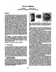
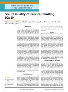
Fig. 1. Instruction set, Programmer’s Model, and Instruction Encoding
3
Our Real-Time Processor
To validate our instruction-level timer extension, we implemented a 25 MHz MIPS-like processor in VHDL on a Xilinx Spartan 3 XC3S200 FPGA. Its design was deliberately simple. It executes a single instruction per cycle with no pipelining. It is centered around a sixteen-bit ALU and sixteen general-purpose registers (register zero always returns zero). Its only novelty is the group of sixteen-bit timer registers, which are controlled by the deadline instruction. Figure 1 shows the instruction formats. We employed a Harvard architecture with 32-bit-wide instructions. Both program and data memory reside on chip. Our applications only required byte-wide data, so our processor only provides byte-wide load and store instructions (data is zero-extended on load). The instruction set, Figure 1, is unremarkable. Arithmetic instructions come in three-register and two-register-with-immediate variants. It is a load/store architecture: only the LB/LBI and SB/SBI instructions transfer bytes to/from memory. The mov instruction is a synonym for or with register $0. 3.1
The Deadline Instruction
The deadline instruction is the main novelty in our processor. It has two formats: dead T, Rs deadi T, imm16 where T is one of the four timer registers $t0, $t1, $t2, or $t3, Rs is one of the sixteen general-purpose registers, and imm16 is a 16-bit immediate data value.
deadi add deadi add (a)
$t0, $r1, $t0, $r1,
cycle −4 −3 −2 8 −1 $r2, $r3 0 10 1 $r2, $r3 2 .. . 7 8
instruction $t0 deadi $t0, 8 3 " 2 " 1 " 0 add $r1, $r2, $r3 7 deadi $t0, 10
" .. . " add $r1, $r2, $r3 (b)
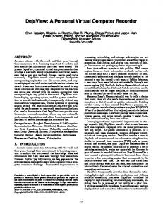
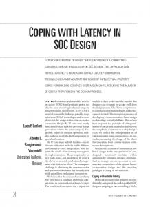
Fig. 2. (a) A code fragment with two deadline instructions and (b) its temporal behavior. The 6 deadline instruction guar5 8 cycles antees the two add in .. structions are executed 8 . cycles apart. 0 9
Each timer register counts down one per cycle, stopping when it reaches zero. When execution reaches a deadline instruction, it pauses there until the given timer register reaches zero. In the cycle following the one in which the timer has a zero count, the timer is reloaded with the source value, either from a register or an immediate value, and the instruction following the deadline executes. Figure 2 illustrates the operation of the deadline instruction. Here, it is being used to ensure that exactly eight cycles occcur between the end of the first deadline and the end of the second. To achieve this, the second deadline delays for seven cycles to compensate for the single cycle add instruction. Assuming the timer $t0 has value 3 when the first deadline is executed, it waits until the timer elapses. (This is implicitly assuming the timer had been set at the beginning of an earlier block.) In the cycle following this (cycle 0 in the figure), the first add instruction executes, then the second deadline delays until cycle 8, when the second add instruction starts. The semantics of the deadline instruction therefore guarantee that the code between the two deadlines takes exactly eight cycles to execute, provided it does not require more. Using deadline instructions is preferable to padding the program with NOPs, the usual technique for achieving such precise timing. A key advantage is that code using deadline does not have to know its execution time. For example, using deadline can deal with loops with a variable (but bounded) number of iterations; inserting NOPs would require the program, at runtime, to calculate the number of cycles the loop took and then delay for the remaining amount of time. Especially when each iteration of the loop is variable (e.g., because of conditionals), this can grow very complex. Reduced code size is another advantage. Except where no NOP-padding is necessary, fewer deadline instructions are necessary to achieve the same effect. Finally, our approach produces a sort of temporal binary compatibility. Provided the numbers loaded in the timers are corrected, a program using our technique that meets all its deadlines will behave identically (i.e., with the same timing and function) on a faster processor.
3.2
Ramifications
Our prototype processor is simple and easy to modify; we expect adding such a deadline instruction to other designs will be just as easy. Modern processors have pipelines and other mechanisms for hiding latency, but since deadline only manipulates special-purpose registers and then only rarely, it should not substantially complicate a pipeline. The delaying effect of the deadline instruction should be able to utilize the standard stalling ability of a pipeline. We intend our extension to be used in a setting where there are many small processors, each running a single hard real-time task. While this is less flexible than an operating system environment, we believe such inflexibility is wise for embedded systems with strict hard real-time constraints. The move toward multi-core processors makes this all the more plausible. We doubt the deadline instruction would work in a multitasking operating system setting, which strives to give processes the illusion of having the processor to themselves. An OS would save and restore timers on context switches, decrementing them when the process is running. However, a na¨ıve scheduler would not be enough to achieve timing goals. While running multiple hard real-time tasks on a single processor is attractive, it leads to the usual challenges of priority assignment, schedulability, etc. One simple case is when a processor is running a single hard real-time task and multiple best-effort ones. In this case, the real-time task could use the deadline instruction to set and achieve deadlines and the processor could run the best-effort tasks when the real-time task was waiting for a timer to expire.
4
A Text-Mode Video Display Controller
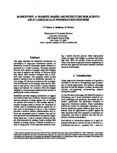
To evaluate our processor, we programmed it to behave as a text-mode video controller. A VGA (640×480) pixel clock is a little over 25 MHz—the clock frequency our processor achieved on the FPGA—so it not fast enough to do something interesting for each pixel. We made register $14 feed an eight-bit video shift register, although we could have used memory-mapped I/O. Figure 3 shows the complete assembly code for our text-mode video controller. Lines 1–3 initializes three constants: the number of character columns (80), the total number of characters to be displayed on the screen (we display an 80 × 30 grid), and the height of each character (16 scan lines). The code on lines 6–47 generates ten blank lines (the back porch), two lines of vertical synchronization, then thirty-three blank lines (the front porch). Each of these uses a loop over each line, and in each loop, timer $t1 is used to ensure each line is exactly 800 pixel cycles long: 96 cycles of horizontal synchronization, 48 cycles of back porch, 640 active cycles, and 16 cycles of front porch. Lines 50–76 is a collection of three nested loops (for characters, lines, and rows) handles the active lines of video. Lines 63–69 fetches each character (line 64 and loads the pixel data for the current line of the character (line 67) into the shift register. Since each character is eight pixels across, the shift register is
1 2 3 4 5 6 7 8 9 10 11 12 13 14 15 16 17 18 19 20 21 22 23 24 25 26 27 28 29 30 31 32 33 34 35 36 37 38 39
movi $11, 80 ; # columns movi $12, 2400 ; = 80 × 30 movi $13, 16 ; lines/character field: ; Vertical front porch movi $1, 0 movi $2, 10 ; number of lines vfrontporch: deadi $t1, 96 ; h. sync period movi $14, VB+HS+HB deadi $t1, 48 ; back porch movi $14, VB+HB deadi $t1, 640 ; active region movi $14, VB deadi $t1, 16 ; front porch movi $14, VB+HB addi $1, $1, 1 bne $1, $2, vfrontporch ; Vertical sync movi $1, 0 movi $2, 2 ; number of lines vsync: deadi $t1, 96 movi $14, VS+VB+HS+HB deadi $t1, 48 movi $14, VS+VB+HB deadi $t1, 640 movi $14, VS+VB deadi $t1, 16 movi $14, VS+VB+HB addi $1, $1, 1 bne $1, $2, vsync ; Vertical back porch movi $1, 0 movi $2, 33 ; number of lines vbackporch: deadi $t1, 96 movi $14, VB+HS+HB
40 deadi $t1, 48 41 movi $14, VB+HB 42 deadi $t1, 640 43 movi $14, VB 44 deadi $t1, 16 45 movi $14, VB+HB 46 addi $1, $1, 1 47 bne $1, $2, vbackporch 48 49 ; Generate lines of active video 50 movi $2, 0 ; reset line address 51 row: 52 movi $7, 0 ; reset line in char 53 line: 54 deadi $t1, 96 ; h. sync period 55 movi $14, HS+HB 56 ori $3, $7, FONT ; font base address 57 58 deadi $t1, 48 ; back porch period 59 movi $14, HB 60 deadi $t1, 640 ; active video period 61 mov $1, 0 ; column number 62 63 char: 64 lb $5, ($2+$1) ; load character 65 shli $5, $5, 4 ; *16 = lines/char 66 deadi $t0, 8 ; wait for next character 67 lb $14, ($5+$3) ; fetch and emit pixels 68 addi $1, $1, 1 ; next column 69 bne $1, $11, char 70 71 deadi $t1, 16 ; front porch period 72 movi $14, HB 73 addi $7, $7, 1 ; next row in char 74 bne $7, $13, line ; repeat until bottom 75 addi $2, $2, 80 ; next line 76 bne $2, $12, row ; until at end 77 78 j field
Fig. 3. Assembly code for the video controller. Code on the left handles synchronization around the active text region. Code on lines 63–69 is the main display loop.
reloaded once every eight cycles, as dictated by the deadline in line 66. This code uses six of these eight cycles; additional tricks, such as restructuring the font in memory to eliminate the shli in line 65, could reduce this. The line loop (lines 53–74) generates sixteen scan lines—one row of characters. It begins by generating a horizontal synchronization pulse: the deadline on line 54 that effectively defines the length of the hsync pulse because the first instruction following it (line 55) turns on the pulse and the instruction after the next deadline—the movi of line 59—turns off the hsync signal. The deadline in line 71 defines the time (16 cycles) of the front porch signal (i.e., horizontal blanking) since just after the next deadline that will be executed (either the beginning of the line loop in line 54 or in the vertical front porch code—line 10) turns on horizontal synchronization. This example illustrates two idioms for timer programming. In one, the deadline statements is placed at the beginning of a block that sets some signals. The interaction between this deadline and the next makes the block run in the prescribed number of cycles prescribed by the first deadline. For example, the deadline in line 54 uses timer $t1 to make sure that the assertion and deassertion of hsync occur exactly ninety-six clock cycles apart. Practically, the deadline in line 54 sets the timer and the deadline in line 58 actually performs the delay. Placing a deadline in a loop forces it to execute with the given period. The deadline in line 66 does this to ensure that a new character is displayed every
1 movi $3, 0x0400 ; final bit mask (10 bits) 2 movi $5, 651 ; half bit time for 9600 baud 3 shli $6, $5, 1 ; calculate full bit time 4 5 wait for start: 6 bne $15, $0, wait for start 7 got start: 8 wait $t1, $5 ; sample at center of bit 9 movi $14, 0 ; clear received byte 10 movi $2, 1 ; received bit mask 11 movi $4, 0 ; clear parity 12 dead $t1, $6 ; skip start bit 13 receive bit: 14 dead $t1, $6 ; wait until center of next bit 15 mov $1, $15 ; sample 16 xor $4, $4, $1 ; update parity 17 and $1, $1, $2 ; mask the received bit 18 or $14, $14, $1 ; accumulate result 19 shli $2, $2, 1 ; advance to next bit 20 bne $2, $3, receive bit
21 check parity: 22 be $4, $0, detect baud rate 23 andi $14, $14, 0xff ; discard parity and stop bits 24 j wait for start 25 26 detect baud rate: 27 movi $6, 0 ; time of start bit 28 wait for start2: 29 bne $15, $0, wait for start2 30 wait for end of start: 31 mov $1, $15 32 addi $6, $6, 3 ; remember end of start bit 33 be $1, $0, wait for end of start 34 sri $5, $6, 1 ; calculate half bit time 35 j got start
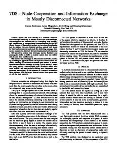
Fig. 4. Assembly code for an asynchronous serial receiver. This reads 8-E-1-formatted data and adjusts the baud rate on a parity error.
eight clock cycles. The loop starts with an lb (line 64) that fetches the character from memory (register $2 holds the address of the leftmost character in the line, and $1 holds the current column number). A shli (line 65) multiplies the character number by sixteen to calculate its offset in the font since each character in the font is sixteen bytes long to produce an 8×16 matrix. We should have arranged the font so that the first line of each character was the first 256 bytes, the next line the next 256, etc., to avoid this shift. The deadline in line 66 guarantees the lb in line 67 that fetches data from the font (the base address for the current line in the character is in $3—it was calculated during horizontal sync), is executed once every eight cycles, i.e., once every eight pixels—exactly the length of the pixel shift register. This example uses two timers: $t1 for the line (horizontal synchronization and blanking), and $t0 for the characters. While a single timer would suffice, using two allows line timing to be separated from character timing. For example, it is possible to display only thirty-five characters across by changing the value in $11, which is compared to the column in $1 at the bottom of the char loop. This changes the execution time of the loop, but since it does not affect timer $t1, the front porch will still come 640 cycles after the end of the back porch because of the earlier deadline instruction. The simplicity of writing software compared to hardware description language was the main reason we undertook this work, and the video controller bears this out: the assembly code for the video controller is only 78 lines. Its behavior matches that of a 450-line VHDL implementation we wrote earlier.
5
An Asynchronous Serial Communication Receiver
We also coded and ran an asynchronous serial communication receiver (half a UART) with auto baud-rate detection. Its real-time constraints are far less stringent than the video controller, but it embodies a richer algorithm because it works with different baud rates. In particular, it uses computed delays to handle different baud rates.
We connected the serial input to register $15, which returns either all 0s or all 1s depending on the serial input, and connected register $14 to a group of LEDs that display the received character. Figure 4 shows the code, which uses our processor’s ability to load timers with non-constant values. The main loop (lines 5–24) waits for the falling edge of a start bit (line 6), delays half a bit time (the contents of $5–line 8), then samples each incoming bit (line 15) and accumulates the result in $14 (line 18). We hold a mask indicating the bit being received in $2 and AND it with the state of the serial port to determine which bit to accumulate in $14. When a parity error occurs (the parity of the received byte is maintained in $4), the code switches over to the detect baud rate routine (lines 26–35). This also waits for a start bit (line 29), but then looks for the next rising edge (line 33), which it assumes is the LSB of the byte being transmitted. The wait for end of start routine calculates how long this takes—relying on the cyclelevel predictability of the processor—and uses it as the new whole-bit time. This can be fooled by bytes whose LSBs are zero. Although a somewhat unfair comparison, a comparable receiver unit of a mini-UART coded in VHDL by Ovidiu Lupas (from opencores.org) is 154 lines long; our receiver is only 35 and includes auto baud rate detection.
6
Conclusions
We presented a processor extension—instruction-accessible timers—that provides real-time programs with cycle-accurate timing. To validate our approach, we implemented a simple MIPS-like processor that runs on a Xilinx Spartan-3 FPGA at 25 MHz and coded a text-mode video controller and a serial receiver for it. In each case, the assembly-language description was about one quarter the size of the equivalent VHDL, and vastly easier to develop and debug. While not helpful for soft real-time tasks, our approach greatly simplifies the development of controllers that previously could only be implemented in hardware or through very careful assembly-level coding. Our contribution is to increase the number of applications that can be coded in a software style, which tends to be much more succinct and easier to get right. We plan to make better use of the time a deadline instruction currently idles the processor. Hardware support to run a best-effort thread during this time is one approach. Thekkath and Eggers [17] discuss when this is wise choice for general-purpose processors, but our aims are different. Running more threads may lead to a hardware fixed-priority preemptive scheduler (Kohout et al. [4]). We also plan to improve the quality of our processor. The MIPS-like architecture we chose was simple to implement but not the best for an FPGA. We will provide higher-level language support, using C macros for timer control. However, we plan to leave the user responsible for specifying the timing constraints, rather than letting, say, the compiler infer them. A compiler able to perform worst-case execution time analysis, however, would be very helpful.
References 1. Dean, A.G.: Compiling for concurrency: Planning and performing software thread integration. In: Proc. Real-Time Systems Symposium, Austin, Texas (2002) 2. Dean, A.G.: Efficient real-time fine-grained concurrency on low-cost microcontrollers. IEEE Micro 24(4) (2004) 10–22 3. Welch, B.J., Kanaujia, S.O., Seetharam, A., Thirumalai, D., Dean, A.G.: Supporting demanding hard-real-time systems with STI. IEEE Trans. on Computers 54(10) (2005) 1188–1202 4. Kohout, P., Ganesh, B., Jacob, B.: Hardware support for real-time operating systems. In: Proceedings of the First International Conference on Hardware/Software Codesign and System Synthesis (CODES+ISSS), Newport Beach, California (2003) 5. Labrosse, J.: MicroC/OS-II. CMP Books, Lawrence, Kansas (1998) 6. Henzinger, T.A., Kirsch, C.M.: The embedded machine: Predictable, portable real-time code. In: Proceedings of the ACM SIGPLAN Conference on Program Language Design and Implementation (PLDI), Berlin, Germany (2002) 315–326 7. Berry, G., Gonthier, G.: The Esterel synchronous programming language: Design, semantics, implementation. Science Comp. Programming 19(2) (1992) 87–152 8. Caspi, P., Pilaud, D., Halbwachs, N., Plaice, J.A.: LUSTRE: A declarative language for programming synchronous systems. In: Proceedings of the Symposium on Principles of Programming Languages (POPL), Munich, Germany (1987) 9. Roop, P.S., Salcic, Z., Dayaratne, M.W.S.: Towards direct execution of Esterel programs on reactive processors. In: Proceedings of the International Conference on Embedded Software (Emsoft), Pisa, Italy (2004) 10. Ferdinand, C., Heckmann, R., Langenbach, M., Martin, F., Schmidt, M., Theiling, H., Thesing, S., Wilhelm, R.: Reliable and precise WCET determination for a real-life processor. In: Proceedings of the International Conference on Embedded Software (Emsoft). Volume 2211 of Lecture Notes in Computer Science., North Lake Tahoe, California (2001) 469–485 11. Engblom, J.: Static properties of commercial embedded real-time programs, and their implication for worst-case execution time analysis. In: Proc. Real-Time Technology and Applications Symposium (RTAS), Vancouver, Canada (1999) 12. Engblom, J.: On hardware and hardware models for embedded real-time systems. In: Workshop on Real-Time Embedded Systems (WRTES), London, UK (2001) 13. Anantaraman, A., Seth, K., Rotenberg, E., Mueller, F.: Enforcing safety of realtime schedules on contemporary processors using a virtual simple architecture (VISA). In: Real-Time Systems Symposium (RTSS), Lisbon (2004) 114–125 14. Anantaraman, A., Seth, K., Rotenberg, E., Mueller, F.: Virtual simple architecture (VISA): Exceeding the complexity limit in safe real-time systems. In: Proc. Intl. Symp. Computer Architecture (ISCA), San Diego (2003) 350–361 15. Schoeberl, M.: Real-time scheduling on a Java processor. In: Proceedings of the 10th International Conference on Real-Time and Embedded Computing Systems and Applications (RTCSA), Gothenburg, Sweden (2004) 16. Hardin, D.S.: Real-time objects on the bare metal: An efficient hardware realization of the Java virtual machine. In: Proceedings of the Fourth International Symposium on Object-Oriented Real-Time Distributed Computing (ISORC), Magdeburg, Germany (2001) 53–59 17. Thekkath, R., Eggers, S.J.: The effectiveness of multiple hardware contexts. In: ASPLOS-VI: Proceedings of the sixth international conference on Architectural support for programming languages and operating systems. Volume 29 of ACM SIGPLAN Notices., San Jose, California (1994) 328–337