A PROPOSED ARTIFICIAL NEURAL NETWORK MODEL for PEM FUEL CELLS Ali Sarı1, Abdulkadir Balikci2, Sezai Taskin3, Serkan Aydin4 1
Electric and Energy Technologies, Celal Bayar University, Turgutlu, Manisa, Turkey
[email protected], 2 Electronics Engineering Department, Gebze Institute of Technology, Gebze, Kocaeli, Turkey
[email protected], 3
Electrical and Electronics Engineering Department, Celal Bayar University, Manisa, Turkey
[email protected], 4
Mechatronics Engineering Department, Celal Bayar University, Manisa, Turkey
[email protected],
Abstract Fuel cells convert the chemical energy directly to the electrical energy and hence they are a very favorable alternative energy source. In the literature, there are many studies related to the modeling of fuel cells. Artificial neural networks (ANNs) is one of the promising techniques for modelling nonlinear systems such as fuel cells. The proposed model in this study doesn’t require many parameters like other studies. Firstly, training and testing data was obtained the dynamic model of a PEM fuel-cell. Then, proposed ANN model outputs are compared with dynamic model ouputs Simulation results shows that the proposed ANN model can be used very efficiently for PEM fuel-cells without using many parameters.
1. Introduction Due to the rapid depletion of fossil fuels and the increase in energy demand, the study of alternative energy sources has increased rapidly. [1] Fuel cells are an alternative technology for energy sources which use hydrogen as a fuel. They are high efficiency conversion systems and these systems produce electricity from hydrogen energy. Fuel cells generate energy by the electrochemical reaction of hydrogen and oxygen [2]. Proton exchange membrane fuel cell (PEMFC) technology is the significant candidate in fuel cell technology due to its highpower density, operation at low temperatures, long cell and stack life [3]. The output voltage of PEM fuel cells is affected by many parameters such as operating temperature, pressure and humidification. In order to improve fuel cell performances, it is essential to understand these parametric effects on fuel cell operations [4]. Due to the complex electrochemical events occurring in a cell, obtained models are quite non-linear. Because of the achievements of the design of non-linear systems, artificial neural networks is a powerful tool for modeling. Artificial neural networks can learn from a set of input–output data without the need of full parameters of the fuel cell system. In
205
the literature, many studies have existence modeling of fuel cells using artificial neural networks. Hatti et al. [5] investigated the static behaviour of the PEMFC taking into different stoichiometric conditions using artificial neural networks. Vicky Rouss et al.[6] investigated nonlinear mechanical behavior of the fuel cell modeled using artificial neural Networks. In [7], ANN model was developed taking into account the transient behavior of the fuel cell. In this paper, a novel Artificial Neural Network (ANN) based model is proposed for PEMFCs. Training data of the ANN model are obtained from dynamic model of the PEM fuel cell (D-PEMFC). The D-PEMFC, previously used in many studies, is realized MATLAB/Simulink. The proposed ANN model is simple and doesn’t require many parameters such as presented in the literature. It requires only fuel cell current and voltage data that include instantaneous value of voltage (kλ), additional three values of voltages which are obtained namely at (k-1)λ, (k-2)λ and (k-3)λ (λ is sampling time), and also sequential voltage differences.
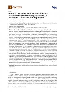
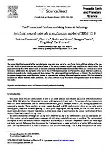
2. Fuel Cells Fuel cells are conversion systems that convert chemical energy into electrical energy by use of chemical reaction. Fuel cell is efficient, quiet and environmentally friendly power generation system [8]. Also, fuel cells don’t have to mechanical components so the losses and noise caused by them are eliminated. Proton exchange membrane fuel cell (PEMFC) is well-known fuel cell type due to its high efficiency and fast start up [9]. PEM fuel cell consists of two electrodes (anode and cathode) and the membrane which separates electrodes (Figure 1). The chemical reactions occurring at the electrodes of a fuel cell are as follows: Anode reaction: 2H2 → 4H+ +4 eCathode reaction: O2 + 4H+ + e- → 2H2O (1) Total cell reaction: 2H2 + O2 → 2H2O + electricity + heat
According to the basic electrochemical relationship between fuel cell current and hydrogen flow, hydrogen flow rate in reaction can be expressed with equation (3);
The products of this process are water, DC electricity and heat [10].
q Hr 2 =
(4)
N 0 I FC = 2 K r I FC 2F
When we use the Laplace transforms of equation (1) and (2), the hydrogen partial pressure can be obtained in the s domain as;
pH 2 =
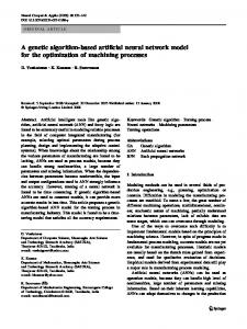
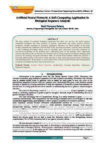
Fig. 1. Schematic of proton exchange membrane fuel cells Figure 2 shows a typcial polarisation curve which is generally used to express the characteristics of a fuel cell. Performance of the fuel cell voltage depends on many variables such as current, temperature, pressure, fuel cell dimensions and stoichiometry of the inlet gases [11]. When the current increases, output voltage of fuel cell decreases. In general, PEM fuel cell has the best performance at temperatures around 70-80 ºC [12].
1/ KH2 ( q Hin 2 − 2 K r I FC ) 1 + τ H2 s
(5)
Van K H2 R T
(6)
where
τ H2 =
Similarly, the partial pressure of oxygen and water can be obtained. When we assumed that temperature, oxygen concentration and output voltage of the fuel cell system constant, it can be expressed by the following equation [13,14].
V cell = E + η act + η ohmic
(7)
In this expression, E is the theoretical voltage produced by Nerst equation
⎡ ⎡ p H Po RT 2 2 E = N 0 ⎢ E0 + log ⎢ ⎢ 2F ⎢ p H 2O ⎣ ⎣
⎤⎤ ⎥⎥ ⎥⎥ ⎦⎦
(8)
where
η act , activation losses
Fig. 2. Polarisation curve of fuel cell
η act = − B ln (C I FC )
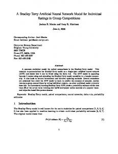
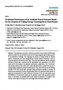
The D-PEMFC model used in this paper is realized in MATLAB/Simulink (Figure 3). In this study, D-PEMFC is realized in MATLAB/Simulink program. D-PEMFC consists of one string of 88 cells connected in series. A cell voltage is assumed to be approximately 0.7 V, output voltage of the PEMFC system is calculated as 0.7x88 = 61.6 V. All the parameters of equations are given in Table 1.
(9)
η ohmic , ohmic losses η ohmic = − R int I FC
(10)
The amount of hydrogen in the hydrogen tank is defined as The relationship between partial pressure of hydrogen and molar flow of any gas (hydrogen) can be expressed as;
q Hreq = 2
q H2 pH2
=
K an M H2
= K H2
(2)
Hydrogen molar flow is defined hydrogen input flow, hydrogen output flow and hydrogen flow during the reaction. This definition can be expressed as;
(
R T in d pH = qH2 − qHout2 − qHr 2 dt 2 Van
)
(3)
206
N 0 I FC 2FU
(11)
Vcell
Dc output voltage of fuel cell system [V]
τ H2
Hydrogen time constant [s]
τ O2
Oxygen time constant [s]
τ H 2O
Water time constant [s]
η act
Activation over voltage [V]
q Hreq
Amount of hydrogen flow required to meet the load change [kmol (s)-1]
2
3. Artificial Neural Networks Artificial Neural Networks simulate working principles of the human brain. Due to the parallel operation structure, computation and information processing competence of artificial neural network is quite successful. ANNs is favourable technique in order to solve a variety of problems in pattern recognition, prediction, optimization and control [15,16].
Fig. 3. Dynamic model of the PEM fuel cell Table 1. Parameters of the fuel cell equations Name
Defining of the parameter
B,C
Constant [A-1] and [V]
E
Nernst instantaneous voltage [V]
E0
No load voltage [V]
F
Faraday’s constant [C (kmol)-1]
IFC
Fuel cell current [A]
Kan
Anode valve constant [ kmolkg (atm s)-1]
KH2
Hydrogen valve molar constant [kmol (atm s)-1]
KH2O
Water valve molar constant [kmol (atm s)-1]
20
KO2
Oxygen valve molar constant [kmol (atm s)-1]
15
Kr
Modeling constant [kmol ( s A)-1]
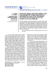
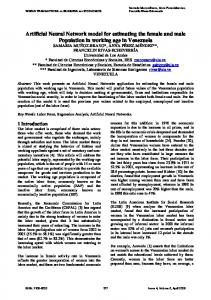
3.1. Preparing of the Artificial Neural Networks Data Training data of the proposed ANN-PEMFC model was obtained from D-PEMFC with sampling time 0.2 s. In order to obtain data sets, D-PEMFC model is simulated with different power values. Figure 4 shows input-output data of the DPEMFC. As shown Figure 4, when current data increased or decreased suddenly, output voltage is decreased or increased, accordingly.
I [A]
Input current data for training and testing of ANN model
-1
10
MH2
Molar mass of hydrogen [kg (kmol) ]
5
N0
Number of series fuel cell in the stack
0 0
PH2
Hydrogen partial pressure [atm]
PH2O
Water partial pressure [atm]
PO2
Oxygen partial pressure [atm]
q O2
Input molar flow of oxygen [kmol (s)-1]
q Hin2
Hydrogen input flow [kmol (s)-1]
q Hout2
Hydrogen output flow [kmol (s)-1]
q Hr 2
Hydrogen flow that reacts [kmol (s)-1]
η ohmic
Ohmic over voltage [V]
R
Universal gas constant [ (1 atm) (kmol K)-1]
Rint
Internal resistance of fuel cell [Ω]
3.2 The proposed Artificial Neural Networks Model
T
Absolute temperature [K]
U
Utilization rate
Van
Volume of anode [m3]
The proposed model’s inputs are fuel cell current data (IFC ), one sampling delayed fuel cell current data, three sampling delayed fuel cell voltages data (UFC ), and sequential voltage and current differences. Inputs of the proposed ANN-PEMFC model is given as follows,
500
1000
1500
2000 Time [s]
2500
3000
3500
4000
(a)
Output voltage data for training and testing of ANN model 69
Vfc [V]
68 67 66 65 64 63 0
500
1000
1500
2000 Time [s]
2500
3000
3500
4000
(b)
Fig. 4. (a) Input current (b) output voltage data for training and testing of ANN model
207
I FC [(k )λ ]
4. Test and Results
U FC [(k − 1)λ ]
Relative error is calculated between the D-PEMFC and ANN-PEMFC using by equation to test achievement of the proposed model.
U FC [(k − 2 )λ ]
(12)
U FC [(k − 1)λ ] − U FC [(k − 2 )λ ]
(UFC [(k−1)λ]−UFC [(k−2)λ]) −(UFC [(k−2)λ]−UFC [(k−3)λ]) I FC [(k − 1)λ ] I FC [(k )λ ] − I FC [(k − 1)λ ]
%e =
In order to model ANN-PEMFC, a multilayer feedforward ANN back-propagation with Levenberg-Marquardt training algorithm is used in this paper. This algorithm is very efficient, fast and easy to implement. Levenberg-Marquardt algorithm is an approximation to Newtons’s method. The update weight vector can be expressed as;
[
]
−1
wji(k +1) = wji(k) − JT J +λI JTE
VD − PEMFC − VANN − PEMFC VD − PEMFC
x 100
(14)
Figure 6-7 shows that output voltage for training ANNPEMFC, D-PEMFC, relative error of the models, respectively. Maximum relative error of training is calculated as % 0.26. The performance of output voltage for testing ANN-PEMFC, D-PEMFC models and relative error are shown in Figure 8. Also, maximum relative error of testing is calculated as % 2.75. The results shown in Figure 6-7-8 denote that the proposed ANN-PEMFC model and D-PEMFC model results have similar behavior in terms of voltage. This result exhibit that the proposed model can be used accurately estimates the output voltage of PEMFC. As seen in Figure 8, the proposed model shows considerably good performance during peak load demand periods such as t=2780 s and t=3100 s in testing of ANN-PEMFC model.
(13)
In equation (13), w ji (k + 1) is a update weight vector,
w ji (k ) is a weight vector, J is a Jacobian matrix, λ is
Output voltage data for training of ANN-PEMFC model
Relative Error [%]
algorithmic parameter, I is a identity matrix and E is a error vector. If algorithmic parameter is selected small value, equation (13) becomes a Gauss-Newton update. On the other hand, algorithmic parameter is selected large value; it becomes a gradient descent update [17]. The ANN consists of fully connected four layers network with two hidden layers. The input layer consists of eight inputs. Each hidden layer has eighteen neurons with tansig activation function. The output layer has one neuron with purelin activation function. The structure of the proposed ANN-PEMFC model is shown in Figure 5.
Voltage [V]
U FC [(k − 3)λ ]
Voltage [V]
I. Input II. Input III. Input IV. Input V. Input VI. Input VII. Input VIII.Input
68 66 64 0
200
0
200
400
600
800
1000 1200 1400 1600 1800 2000 Time [s] Output voltage data for training of D-PEMFC model
400
600
800
68 66 64 1000 1200 1400 1600 1800 2000 Time [s]
Relative error data for training of ANN-PEMFC and D-PEMFC model 0.1 0.05 0
0
200
400
600
800
1000 1200 1400 1600 1800 2000 Time [s]
Fig. 6. Output voltage data for training of ANN-PEMFC and D- PEMFC models (t=0 to 2000 s)
Fig. 5. Structure of the proposed network The data set obtained MATLAB/Simulink used to train and test the proposed ANN model. Figure 4 shows this data set which consist two parts. The training set is selected between interval of t=0 to 2000 s and t=3201 to 4000 s. The test data is selected within the interval of t=2001 to 3200 s.
208
Applied Thermal Engineering, vol. 27, pp. 2294-2299, 2007 [2] Ural Z., Gümüş B., Gençoğlu M. T., “Bir Pem Yakıt Pili Sisteminin MATLAB ile Modellenmesi”, YEKSEM’07, Gaziantep, 2007,pp.106-112 [3] Bıyıkoglu A., “Reviewof proton exchange membrane fuel cell models”, International Journal of Hydrogen Energy, vol. 30, pp. 1181 – 1212, 2005 [4] Wang L., Husar A, Zhou T., Liu H., “A parametric study of PEM fuel cell performances”, International Journal of Hydrogen Energy , vol. 28, pp. 1263 – 1272, 2003 [5] Hatti M., Tioursi M., Nouibat W., “Static Modelling by Neural Networks of a PEM Fuel Cell”, IEEE Industrial Electronics, Paris, 2006, pp.2121-2126 [6] Rouss V., Charon W., “Multi-input and multi-output neural model of the mechanical nonlinear behaviour of a PEM fuel cell system”, Journal of Power Sources, vol. 175, pp. 1–17, 2008 [7] Zamora I., San Martín J.I., San Martín J.J., Aperribay V., Eguía P., “Neural Network Based Model for a PEM Fuel Cell System”, International Conference on Renewable Energies and Power Quality (ICREPQ’09), Valencia, 2009 [8] Puranik S.V, Keyhani A., Khorrami F., “Neural Network Modeling of Proton Exchange Membrane Fuel Cell”, IEEE Transactions on Energy Conversion, vol. 25, no. 2, pp. 474–483, June, 2010 [9] Jemei S., Hissel D, Péra M.C, Kauffmann J.M, “On-board fuel cell power supply modeling on the basis of neural network methodology”, Journal of Power Sources , vol.124, pp. 479–486, 2003 [10] Maher A.R., Al-Baghdadil S, “Modelling of proton exchange membrane fuel cell performance based on semiempirical equations”, Renewable Energy, vol. 30, pp. 1587-1599. 2005 [11] Balkin A.R., “Modelling a 500 W Polymer Electrolyte Membrane Fuel Cell”, Bachelor Degree, University of Technology Sydney, 2002 [12] Larminie, J., Dicks, A., “Fuel Cell System Explained”, John Wiley & Sons Ltd, West Sussex,England, 2001 [13] Uzunoglu M., Alam M.S., “Dynamic Modeling, Design, and Simulation of a Combined PEM Fuel Cell and Ultracapacitor System for Stand-Alone Residential Applications”, IEEE Transactions on Energy Conversion, vol. 21, no. 3 ,pp 767-775, September 2006 [14] El-Sharkh M.Y., Rahman A., Alam M.S., Byrne P.C, Sakla A. A, Thomas T., “A dynamic model for a standalone PEM fuel cell power plant for residential applications”, Journal of Power Sources, vol.138, no.1–2, pp. 199–200, 2004 [15] Xiuping Y., Zuhua F., Tao S., Sijia Y., “Research on Neural Networks Identification of a Nonlinear Modeling for PEMFC”, Fifth International Conference on Natural Computation, Tianjin, 2009 [16] Saengrung A, AbtahiA., Zilouchian A., “Neural network model for a commercial PEM fuel cell system”, Journal of Power Sources ,vol.172, pp. 749–759, 2007 [17] Aydin S., Kilic I., Temeltas H., “Using Linde Buzo Gray Clustering Neural Networks for Solving the Motion Equations of a Mobile Robot”, Arab J Sci Eng , vol.36, pp:795–807,2011
Voltage [V]
Output voltage data for training of ANN-PEMFC model 68 66 64
V oltage [V]
3200
3400 3500 3600 3700 3800 3900 Time [s] Output voltage data for training of D-PEMFC model
4000
68 66 64 3200
Relative E rror [%]
3300
3300 3400 3500 3600 3700 3800 3900 4000 Time [s] Relative error data for training of ANN-PEMFC and D-PEMFC model
0.2 0.1 0 3200
3300
3400
3500
3600 Time [s]
3700
3800
3900
4000
Fig. 7. Output voltage data for training of ANN-PEMFC and D- PEMFC models (t=3200 to 4000 s)
Voltage [V]
Output voltage data for testing of ANN-PEMFC model 68 66 64
Voltage [V]
2000
2200
2400 2600 2800 3000 Time [s] Output voltage data for testing of D-PEMFC model
3200
68 66 64
Relative Error [%]
2000
2200
2400
2600 2800 3000 3200 Time [s] Relative error data for testing of ANN-PEMFC and D-PEMFC model
2200
2400
3 2 1 0 2000
2600 Time [s]
2800
3000
3200
Fig. 8. Output voltage data for validation of ANN-PEMFC and D- PEMFC models
5. Conclusion In order to model PEMFCs, an ANN based model is proposed in this study. The proposed ANN model needs only two parameters which are the voltage and the current data. The simulation results indicate that the proposed ANN model can predict the stack voltage successfully. It has good prediction accuracy and small relative error. Despite of sudden load changes, the proposed ANN-PEMFC model yields accurate prediction. Consequently, it is a more suitable model for hybrid vehicle and hybrid power generation system. Future work will on different artificial intelligence techniques such as fuzzy logic and ANFIS. Moreover, the proposed model performance can be tested using the real fuel cell parameters.
7. References [1] Hussain M. M., Dincer I., Li X., “A preliminary life cycle assessment of PEM fuel cell powered automobiles’’,
209