simulate real driving and the camera simulates the driver's view. ... Permission to make digital or hard copies of all or part of this work for personal or ... presents data without blocking the user's view. .... components of the system are a laptop, a video camera, a .... is extracted and used by the framework to recover the ori-.
A Prototype of Landmark-Based Car Navigation Using a Full-Windshield Head-Up Display System Wen Wu, Fabian Blaicher, Jie Yang
Thomas Seder, Dehua Cui
Carnegie Mellon University 5000 Forbes Ave, Pittsburgh, PA 15213, USA
General Motors Research & Planning Detroit, MI 48232 USA
ABSTRACT
1.
In driving applications, a full windshield head-up display (FWD) system provides a flexible way for delivering driving related information. The projected information (text, image and graphics) is distorted on the car windshield because of its non-planar surface, the FWD projector’s position and the viewing angle of the driver. In this paper, we present development of a prototype of landmark-based car navigation using an FWD system. We propose to use a computer vision method to automatically correct FWD projection distortion on the windshield. Our system consists of an FWD, a camera and an LCD video projector. In the calibration phase, the camera captures the patterns projected by the FWD projector and our method automatically models the windshield distortion. In the working phase, the LCD video projector projects a video sequence (that is captured on a moving vehicle in the real driving situation) onto a wall to simulate real driving and the camera simulates the driver’s view. Our system aims to detect and highlight key landmarks such as road signs on the windshield by controlling the FWD projector to provide better navigation information. We demonstrate the proposed concept using our previously developed street landmark detection system.
Navigation is the process of planning, recording, and controlling the movement of a craft or vehicle from one place to another. 1 Navigating a vehicle in dynamic environment is one of the most demanding activities for drivers in daily life. American people drive about 12,000 miles per year in average. Studies have long identified the difficulties that drivers have in planning and following efficient routes [1, 2, 3]. A route guidance system (also termed vehicle navigation system) is usually a satellite navigation system designed for use in vehicles. Most systems typically use a combination of Global Positioning System (GPS) and digital map-matching to calculate a variety of routes to a specified destination such as a shortest route. They then present map overview and turn-by-turn instructions to drivers, using a combination of auditory and visual information. A typical turnby-turn instruction is an auditory such as ”turn right in 200 feet”, accompanied by a visual right turn arrow plus a distance-to-turn countdown that reduces to zero as the turn is approached. Route guidance systems generally function well although they are wholly dependent on the accuracy of the underlying map database and availability of GPS signal. However, from a human factors perspective, there are several potential limitations to the current design [4]: mainly presenting procedural and paced navigation information to the driver, and relying on distance information to enable a driver to locate a turn. Current navigation systems have not yet reached their full potential and their use is often not intuitive and helpful to users with different abilities. There are two main kinds of navigation interfaces in existing systems, i.e. voice commands and abstract map images on a display, either integrated in the dashboard or being portable. Both interfaces have proven useful and effective but not best. For example, current navigation systems can increase a driver’s cognitive load because the driver has to map the information provided by the navigation system to the real environment outside the windshield. Another distracting effect of current navigation systems is that the driver has to move his/her attention away from the road to perceive navigation information. The head-up display (HUD) is a type of display that presents data without blocking the user’s view. The technique was pioneered for military aviation and now used in commercial aviation, motor vehicle and other cases. Since 1988, General Motors has popularized HUDs on the Olds Cutlass, Pontiac Grand Prix, Bonneville, Buick LeSabre, Park Avenue and Rendezvous. In 1999, Automotive HUD
Categories and Subject Descriptors J.7 [Computer Applications ]: COMPUTERS IN OTHER SYSTEMS: Consumer products
General Terms Design, Experimentation
Keywords Landmark-based car navigation, full-windshield head-up display, automatic windshield distortion correction, street landmark detection
Permission to make digital or hard copies of all or part of this work for personal or classroom use is granted without fee provided that copies are not made or distributed for profit or commercial advantage and that copies bear this notice and the full citation on the first page. To copy otherwise, to republish, to post on servers or to redistribute to lists, requires prior specific permission and/or a fee. AMC’09, October 23, 2009, Beijing, China. Copyright 2009 ACM 978-1-60558-760-8/09/10 ...$5.00.
1
INTRODUCTION
http://en.wikipedia.org/wiki/Navigation# ref-bow799 0
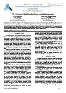
Figure 1: The FWD setup. (a) an overview with annotation; (b) the front-view of the video projector and the FWD laser projector; (c) the back-view of the windshield. technology made a big quality leap with the Chevrolet Corvette. The new Corvette, which uses a HUD to display vehicle speed, engine RPM, navigation and more, has proven the HUD to be one most popular option. As of 2006, BMW featured the HUD as an option on their 5 and 7 series vehicles, with more HUDs anticipated from other European and Japanese OEMs. Despite the limited resolution and current generation HUDs’ sizes, they provide information such as speed, turn by turn navigation and warnings via a virtual image projected onto the windshield by mirrors within the driver’s normal field of vision. By adjusting the number of mirrors, display color and illumination elements, installation space requirements and costs can be adapted to respective vehicle models. In this research, we are developing technologies for next generation navigation systems using a full windshield headup display (FWD) system manufactured by SuperImaging Inc [5]. An FWD can project information everywhere on the windshield while HUD projects information in a limited windshield region. In driving applications, an FWD system provides a flexible way for delivering information. An FWD can highlight important street landmarks such as speed limit signs, store signs, etc. Available technologies to detect and recognize street landmarks have been proposed in our previous works [6, 7] It can be used to enhance the vision of the driver in dangerous situations. Infrared cameras or laser scanner can gather information from the car surroundings which is not easily visible to the driver in poor lighting conditions. Deer, pedestrians or bicyclists can be detected and highlighted. So common dangerous situations can be avoided by showing threats on the FWD. In situations such as bad weathers, an FWD can also be used to highlight street boundaries which can especially help old people with weak vision capabilities. Directly projecting text, images and graphics on the FWD’s windshield causes distortion because of the windshield’s nonplaner surface. We assume that the viewing angle of the driver is fixed. Conceptually, our method can be extended to deal with changing viewing angles. Distortion correction is the prerequisite for an FWD. In this paper we propose to use a computer vision system to automatically correct distortions at different locations of the windshield. Our system consists of an FWD, a camera, and an LCD projector. In the
calibration phase, the camera will capture the patterns generated by the projector and the system will automatically model the distortions. In the working phase, the LCD video projector projects a video sequence onto a wall to simulate driving situation. We demonstrate the feasibility of the proposed concept using the road sign detection results from our previously developed road sign detection system [6].
2.
MOTIVATION
Humans often uses landmarks for navigation. For example, we tell people to turn left after a BP gas station and to make a right at Starbucks. In our daily life, a landmark can be anything that is easily recognizable and used for giving navigation directions, such as a sign or a building. It has been shown that current navigation systems can be made more effective and safer by including landmarks as key navigation cues [8]. Especially, landmarks support navigation to unfamiliar destinations. By providing external reference points which are easily remembered and recognized, they can potentially reduce the need to refer to an information display in order to locate a navigation decision point. The definition of landmark in navigation context has been studied from varying theoretical perspectives. Lynch described landmarks as external reference points which are easily observable from a distance [9]. Kaplan defined a landmark as ”a known place for which the individual has a well formed representation”, and described two theoretical factors that lead to a object or place acquiring landmark status: the frequency of contact with the object or place, and its distinctiveness [10]. Three type of distinctiveness were proposed: visual distinctiveness (a predominantly objective quality relating to the physical attributes that discriminate the landmark from the surrounding environment); inferred distinctiveness (knowledge concerning its structure or form that makes the landmark stand out from what is usual); functional distinctiveness (the salience in terms of the goals or sub-goals of the landmark). In addition to the visual characteristics of landmarks and their functional or social importance, the location of an object within the environment has also been shown to impact significantly on its effectiveness as a landmark [11, 12]. Burnett identified 4 out of 11 attributes that were most important characteristic of ’good’ landmarks for route guidance systems [8]:
1. Usefulness of location: the ease with which the location of the landmark allows a navigational maneuver (e.g. a turning) to be identified. 2. Visibility: whether the landmark’s size and shape mean it can be seen clearly in all conditions. 3. Uniqueness: whether the appearance of the landmark is such that it is unlikely to be mistaken for anything else. 4. Permanence: the likelihood of the landmark being present. Based on the human factor studies using above attributes Burnett further identified the top ten scoring landmarks in United Kingdom (UK) based on the overall scenario [8]: 1. 2. 3. 4. 5.
Traffic lights Pelican crossing Bridge over road Hump-backed bridge Petrol station
6. 7. 8. 9. 10.
Monument Superstore Street name signs Railway station Church
It is quite evident that several these landmarks are UK specific. In United States, we observe that commonly used street landmarks include 1) road signs, 2) store signs including gas stations, fast food restaurants, stores, subway stations, etc and 3) buildings including churches, superstores, etc. In the following, we mean these three classes of landmarks when we use the term street landmarks. In this paper we only demonstrate road sign detection and highlight on FWD.
3.
RELATED WORK
There has been much research directed to driving assistance systems, car navigation and HUD. Liu et al. [13] have compared driving performance and psychological workload of drivers using a head-down display and an HUD. The results showed that the response time to urgent events is faster produces less mental stress with an HUD. Wu et al. [14] presented a multimedia system for route sharing among users and navigation by overlaying turning arrows and highlighting landmarks in videos. Chu et al. [15] have recently proposed to use a full-windshield HUD to show various information to a driver. However, they have not presented a working system in the paper. Sato et al. [16] constructed a similar setup to ours with an FWD but use a different projection technology. Our system includes a new FWD system, a camera, a LCD projector and a road sign detector.
4.
SYSTEM PROTOTYPING USING AN FWD
Our driving assistance system for highlighting landmarks on an FWD can be used in real-time applications and is robust to different lighting and road conditions. The main components of the system are a laptop, a video camera, a TM laser projector, a dedicated controller, and a MediaGlass windshield which is covered with transparent phosphors to reflect blue or red light emitted by the laser. The system provides easier navigation with less distraction for safer driving. Fig.1 shows the setup of our experimental system. We tested our system inside a laboratory and simulated different test driving scenarios with an LCD projector.
Figure 2: Distortion correction for FWD. (a) Initially corrected projected laser points from the video. (b) Corrected projection grid. Upside down axis due to laser projection scheme.
4.1
Non-Planar Windshield Distortion
Before using the FWD we need solve one key problem correcting the to-project data to avoid windshield distortion. All images projected to the windshield are distorted. We solve this problem, by applying two pre-warp functions f (x, y) and g(x, y) to all images before projecting them to the windshield. Assume projected laser points’s coordinates in the camera view as (xi , yi ) : i = 1, ..., N and in the laser projector plane as (ui , vi ) : i = 1, ..., N . We want to find the functions f (x, y) and g(x, y) such that f (xi , yi ) ≈ ui , g(xi , yi ) ≈ vi , i = 1, ..., N.
(1)
The process of generating the pre-warp information for the distortion correction is as follows: the first step is to project a pattern on the windshield and capture the result. This pattern is used to compute the correct pre-warped points. Any arbitrary point can be correctly projected on the windshield with interpolation based on the pre-warped points. Creating the pre-warping information poses different challenges, which are influenced by different aspects. The lighting conditions of the experimental setup or partly occlusion of the windshield play a role here. The non-planar surface correction is sensitive to movements of the FWD projector and the windshield which are fixed in our setups and expected commercial uses.
4.2
Automatic Distortion Correction
The process to correct distortion on a windshield is as follows. The first step for constructing the pre-warp mapping is measuring the windshield. Therefore we project a special pattern on the windshield and record it with a camera. The next step is to compute a pre-warp function by using the correspondence from the projected points to the recorded points. With this function we can adjust images so they do not look distorted to the driver. This image will then be projected to the windshield. The calibration process for the pre-warp function must only be done once. After registering the surface of the windshield one can use the pre-warp function independently of the position of the driver just by small adjustments. For the first step we project a pattern to the windshield. Our use pattern is a grid of blue points which forms the shape of a rectangle. We choose a grid of 30 points per row and 20 points per column. All points are projected for 250 ms. Shorter time intervals lead to disturbing artifact from the laser moving between the points. A pattern of grid
Figure 3: (a) shows a typical icon used as input for the FWD. (b) shows the same icon after the prewarp function is applied.
points is chosen, because other patterns commonly used by a calibration process like check boards, cannot be projected by FWD because FWD cannot project filled areas properly. The projected pattern is recorded to video by an ordinary digital camera on a tripod. This camera represents the view of the driver. Before extracting the points from the recorded video we have to compensate for different lighting conditions, because the recognition of the laser grid points is sensitive to bright spots. All possibly disturbing light sources should be removed, for example reflections on the windshield frame. Therefore we mask the image from which we extract the coordinates and use solely the part which contains the windshield. Additionally we limit the color information in the extracted images to the blue color channel. The reasoning behind is that the calibration process only uses blue laser rays. A different part of the complexity of the extraction process is due to small parts of the windshield which are occluded from the laser projector. Additionally are several other points which cannot be extracted from gathered data. The projected pattern is larger than the windshield and therefore are some points not projected to the reflecting windshield. We must compensate for them as we need to find the relations between all projected and captured points. Another problem that occurs is that some extracted frames from the video contain artifacts from the previous projected grid points. Our approach to correct bad or missing points is creating an interpolating spline curves for each row of points. These splines compensate for missing points or smooth out existing points. We used piecewise polynomial functions of degree two because they fitted the best to the curved windshield surface. Fig.2 shows comparison between initially extracted laser points and corrected projection grid. Based on the extracted points we create the pre-warped points. We are using the correspondence of the coordinates of the distorted points extracted from the camera (x, y) to the coordinates used to control the laser (u, v) to generate a mapping. Therefore we compute a new orthogonal grid of points in the coordinates of the camera (x, y). For all these new points we use interpolation to compute the warped points in the coordinate system of the laser (u, v). We use a 2D linear hyper-surface fitting function for the interpolation which computes the pre-warped points from the new grid points, the extracted laser coordinates and the corresponding coordinates (u, v). The new interpolated points are used as input for pre-warp functions to project images on the FWD. The pre-warped points can be used to project
Figure 4: The architecture of the road sign detection framework. a grid of undistorted points to the windshield. To reach the goal of projecting any image to an arbitrary position we use interpolation to correct points between the pre-warped grid points. With the pre-warp function FWD can display arbitrary images on arbitrary positions. Fig.3a shows an image before pre-warping is applied. Fig.3b shows the pre-warped image. One can see that not only is the image distorted, but the size changed significantly.
5.
DETECTION OF STREET LANDMARKS
Road sign is an important kind of street landmark. We have proposed a system that can incrementally detect text on road signs from video [6]. In previous work, some researchers were able to detect scene text from still images [17]. Text in video can be classified into two classes: graphic text and scene text [18]. Graphic text is text that is added to the video after the video is captured, such as captions added to news videos. Scene text exists as part of objects in a natural environment when it is directly captured by a camera, which includes billboards, and street names on road signs. Our system naturally employs a divide-and-conquer strategy to decompose the original task into the two subtasks, namely: 1) localizing road signs and 2) detecting text. Because of government requirements on the design and placement of road signs, our observation shows that 1) text on road signs has higher contrast compared to most sign background colors; 2) text on the same road sign always has similar foreground and background patterns; 3) most road signs exist on vertical planes; and 4) there are only a limited number of colors used as background colors. Our system ( Fig.4 shows the architecture) has four steps: 1) Discriminative points detection and clustering that detects discriminative feature points in every video frame and partition them into clusters. 2) Road sign localization that selects candidate road sign regions corresponding to clusters of feature points using a vertical plane criterion. 3) Text detection that detects text on candidate road sign areas and track them. 4) Text extraction and recognition that extract text in candidate sign plane for recognition given a satisfactory size. Our proposed framework possesses are the following unique properties. First, the number of selected points in step 1,
N , balances the sign localization speed and system process rate because more feature point’s likelihood that the sign is located early. A large number of feature points also mean intensive computation. Second, spatio-temporal information is extracted and used by the framework to recover the orientation of potential planes in the 3D space. Once a point cluster is classified as a vertical plane, the text detection algorithm will be run on it. Third, the framework applies a feature-based tracker which can track a feature point in a subpixel level. The corners of detected road sign areas and minimal bounding box are tracked to the next frame by averaging the motions of the nearest points of each corner. There are two reasons for tracking discriminative points instead of the boundary corners directly: 1) boundary corners may not be a good feature to track compared to those selected points; and 2) tracking the selected points on the road sign area can relieve the problem of partial occlusion when it happens in video. This framework possesses two unique merits: 1) by applying the divide and conquer strategy, the first two steps of the algorithm can significantly narrow down the search space for the later text detection step and thus reduce the majority of false hits which occur in the case of the whole-image text detection; 2) it takes advantage of both temporal and spatial information in video for detecting text on road signs over the timeline. More generally, a street landmark means anything that is easily recognizable, such as a monument, a building, a store sign, or other structure. In our application domain, we refer to street landmarks as objects that can be used for giving directions for driving navigation. In an urban environment, commonly used street landmarks include gas stations, fast food restaurants, and churches, etc. Our research efforts are motivated by the observation that we (drivers) often use landmarks for helping navigation. We would like our implemented system could help drivers navigate by automatically recognizing these landmarks from the video sequence. We have proposed such a system in [7] in which we assume that only one image per landmark is available for training in this task and training and the test images have different quality and resolution.
6.
RESULTS AND DEMOS
Fig.5 shows three testing examples of different icons that are projected at different locations without any distortion in the camera view. Using a pre-warp function together with a look-up table of pre-warped points allows for fast correction in real-time projections. Due to the use of interpolation between the pre-warped points does the projection program need only little memory. This is especially valuable in cars with limited computer systems. As the installation TM of the MediaGlass and the laser projector was not in a real car, we used video projection of different self-recorded drives for the simulation. Qualitative evaluation of the resulting projection on the windshield shows that the approach was successful. The pre-warp function completely compensates distortion of the windshield. The FWD projection on the windshield is bright and clearly visible. Thus the proposed windshield distortion correction method is beneficial in other applications. Another two demos with highlighted road signs in two sequences on the FWD also shows promising results. The demos use outputs from our previously developed road sign de-
tector [6] that gives locations of detected signs in the videos. The signs are highlighted by FWD. Fig.6 shows two demo sequences in which the highlighted (by FWD) road sign is presented in the simulated driver view. Highlighting landmarks like roads signs can help the driver while navigating. It is not clear if distraction of FWD projection revokes the advantages of the provided navigation info. Our results shows FWD can give the driver helpful guidance with help of other vision sensors and systems and offer a good basis for future research. A video showing all above demos is available at http://www.cs.cmu.edu/∼wenwu/publications/FWD.wmv (made by Windows Movie Maker, test playing on Windows Media Player 10. When copying the above URL, note to correct the title character after copying for the correct address).
7.
CONCLUSIONS AND FUTURE WORK
We showed that highlighting landmarks on an FWD is possible and can help the driver to navigate more easily and convenient in complex driving situations. We projected a grid point pattern with the FWD, recorded the pattern and created a function to correct for the distortion based on pre-warped points and interpolation. Our experimental setup was used to project route guidance information on a prototype FWD. Landmarks such as road signs were used as support for navigation. Although the current cost for the prototype is relatively expensive, the prospect of proposed system can be greater when the cost decreases in the future. In our experiments we assume that the viewing angle of the driver is fixed (driver position and head orientation), which is essential for our proposed automatic distortion correction method to work. The assumption is limited and not the case in a real driving situation. Therefore, in future work we will introduce a head-tracking system with the goal that the driver sees the images on the windshield matching the environment independently of his/her perspective. The analysis of psychological effects of using an FWD are not part of this work. Further research on this topic are required before installing FWDs in mass produced cars, because the effects on psychological workload of the driver must be fully understood. The detection of road signs could be extended to detect pedestrians, bicyclists or deer on the street by a thermal camera, so the driver could be warned in advance of dangerous situations. We are also interested in using FWD to highlight street boundaries in difficult weathers. The possible future design and implementation based on FWD would be guided by the analysis of human psychological effects, in a human-centered design manner.
8.
ACKNOWLEDGEMENTS
This work was funded by General Motors. The visiting of F. Blaicher at CMU was funded by the International Center for Advanced Communication Technologies (interACT). We also want to thank Martin B¨ auml for his helpful suggestions.
9.
REFERENCES
[1] G. F. King, “Driver performance in highway navigation tasks,” Transportation research record, 1986. [2] L. A. Streeter and D. Vitello, “A profile of drivers’ map-reading abilities,” Human factors, 1986.
Figure 5: Distortion correction test examples: a rectangle in (a), an arrow in (b) and another arrow in (c). Patterns in the light blue boundary, which are projected by the FWD laser projector at different windshield locations, show no distortion. [3] W. W. Wierwille, J. F. Antin, T. A. Dingus, and M. C. Hulse, “Visual attentional demand of an in-car navigation display system,” Vision in vehicles II, 1989. [4] Andrew J. May and Tracy Ross, “Presence and quality of navigational landmarks: Effect on driver performance and implications for design,” Human Factors: The Journal of the Human Factors and Ergonomics Society, 2006. [5] Superimaging Inc., “2-color full-windshield display system,” www.superimaging.com. [6] Wen Wu, Xilin Chen, and Jie Yang, “Detection of text on road signs from video,” IEEE Transactions on Intelligent Transportation Systems, 2005. [7] Wen Wu and Jie Yang, “Object fingerprints for content analysis with applications to street landmark localization,” Proceedings of ACM Multimedia, 2008. [8] G.E. Burnett, “Turn right at the king’s head”: Drivers’ requirements for route guidance information.,” PhD thesis, Loughborough University, UK, 1998. [9] K. Lynch, The Image of the City, MIT Press, 1960. [10] S. Kaplan, “Adaption, structure and knowledge,” Environmental Knowing: theories, research and methods, 1976. [11] S. Carr and D. Schissler, “Perceptual selection and memory in the view from the road,” Environment and behaviour, 1969. [12] G. L. Allen, A. W. Siegel, and R. R. Rosinski, “The
[13]
[14]
[15]
[16]
[17]
[18]
role of perceptual context in structuring spatial knowledge,” Journal of Experimental Psychology, 1978. Yung-Ching Liu and Ming-Hui Wen, “Comparison of head-up display (HUD) vs. head-down display (HDD): driving performance of commercial vehicle operators in taiwan,” International Journal of Human-Computer Studies, 2004. Wen Wu, Jie Yang, and Jing Zhang, “A multimedia system for route sharing and video-based navigation,” Intl. Conference on Multimedia & Expo (ICME), 2006. Kar-Hai Chu, Robert Brewer, and Sam Joseph, “Traffic and navigation support through an automobile heads up display (a-HUD),” ICS2008-05-02, Tech Report, Univ. of Hawaii at Manoa, 2008. Akihiko Sato, Itaru Kitahara, Yoshinari Kameda, and Yuichi Ohta, “Visual navigation system on windshield head-up display,” 13th World Cong. on Intelligent Transp. Sys., 2006. X. Chen, J. Yang, J. Zhang, and A. Waibel, “Automatic detection and recognition of signs from natural scenes,” IEEE Trans. on Image Processing, vol. 13, no. 1, January 2004. R. Lienhart, “Automatic text recognition for video indexing,” Proc. ACM Multimedia, 1996.
Figure 6: A road sign is highlighted by FWD projection (in blue) over time that overlays the sign on the wall projected by a video projector. Two demo sequences are in (a) and (b).