works: circuit switching, packet switching and burst switch- ing. Current .... (8) Slot transmission mode. In this mode, DBs are transmitted in units of slots, and.
A QoS Supporting Scheduling Algorithm for Optical Burst Switching DWDM Networks Mei Yang and S.Q. Zheng
Dominique Verchere
Department of Computer Science Univ. of Texas at Dallas Richardson, TX 75083-0688, USA
Research & Innovation Alcatel USA Richardson, TX 75081, USA cally attainable for a long time. Optical burst switching (OBS) has been proposed as a combination of the merits of optical circuit switching and optical packet switching while avoiding their shortcomings. Pioneering work on optical burst switching was reported in [14], [18], and further discussions can be found in [10], [12], [13], [15], [16]. In an OBS DWDM network, the control packet (header of a burst) is transmitted on a separate wavelength ahead of the transmission of burst payload to ensure sufficient time for header processing. Compared with OCS, OBS provides improvement over wavelength routing in terms of efficiency and scalability by statistical multiplexing bursts (of packets). The pretransmission latency of OBS is lower than that of OCS. OBS requires limited or even no delay of the data at intermediate nodes as OCS, and achieves an efficient bandwidth utilization as OPS. OBS is easier to implement than OPS because of less stringent requirement in processing control signals and achieving synchronization. The amortized overhead in routing and forwarding of an OBS router can be much smaller than that of an OPS router. One of the major challenges in the design of OBS core router is the data channel scheduling algorithm. Several scheduling algorithms have been proposed to schedule bursts efficiently while achieving a high bandwidth utilization at the same time, such as LAUC-VF [6] and JET [10]. QoS is an extremely important aspect of IP-over-WDM. An IP QoS model that has been studied extensively is the integrated service (Intserv)[2]. Intserv requires a signaling mechanism, such as RSVP [3], to reserve network resources along the flow path. With Intserv, each packet is processed by the router to determine its service class. In large IP networks, processing and policing individual packets impose a computation burden on the packet forwarding engine that limits the scalability of Intserv. The differentiated services (Diffserv) model [11] was introduced to deal with the scalability issue in the Intserv model. In Diffserv, scalability is achieved by aggregating packets with the same QoS requirement into fewer but coarser-grained flows. Diffserv flows are enforced locally on per-hop basis, simplifying the complexity of end-to-end QoS policing mechanism. By closely examining the various characteristics of Multi-protocol Label Switching (MPLS) [17], one can see that it is a very good candidate for providing Diffserv [8]. Traffic classification, its ability to reserve Class of Services (CoS) through its lightweight signaling protocol LDP (Label Distribution Protocol) and label aggregation feature are some of its useful properties [7]. While MPLS was originally intro-
Abstract-The ubiquity of IP has led to IP-over-WDM as the core architecture for the next-generation optical Internet. Optical Burst Switching(OBS) has been proposed to be a competitive switching technology for DWDM networks. Data channel scheduling Algorithm is one of the major challenges in OBS. The same-service-to-all model of the current Internet is inadequate for the diverse quality of service expectations of Internet applications and users. Differentiated Service (DiffServ) was proposed to provide a scalable and manageble architecture for service differentiation in IP networks. This paper proposes a scheduling algorithm based on an existing LAUC-VF algorithm to support DiffServ and takes advantage of MPLS. Simulation results demonstrate that this algorithm has better QoS performance than the existing LAUC-VF algorithm.
I. I NTRODUCTION Fiber optics is a future-proof technology. In response to the exponential growth of bandwidth demand, dense wavelength division multiplexing (DWDM) has been deployed. With DWDM, it is now possible to transmit different wavelengths of light over the same fiber, which has provided another dimension to increasing bandwidth capacity. Meanwhile, the ubiquity of Internet Protocol (IP) has led to much-touted IP-overWDM as the core architecture for the next-generation Optical Internet. Harnessing the bandwidth in an efficient and scalable way is vital to the eventual realization of such a vision. Basically, there are three switching methods for DWDM networks: circuit switching, packet switching and burst switching. Current deployment of DWDM uses optical circuit switching (OCS), which takes the form of wavelength routing [4], [5]. Since the Internet traffic is self-similar (bursty at all time scales), wavelength routing results in a low bandwidth utilization. In addition, given the number of available wavelengths is limited, not every node can set up a dedicated lightpath to every other node. Coupled with the considerable lightpath set-up time, this limitation makes circuit switched DWDM network inflexible and unscalable for implementing IP-overWDM. A longer-term strategy for network evolution employs optical packet switching (OPS), which provides better flexibility, resource utilization, functionality and granularity [12], [19], [20], [21], [22]. One of the biggest challenges is that there is no optical equivalence of the random access memory. At present, it seems that the most feasible way to implement optical buffering is to use fiber delay lines (FDLs). Another major challenge is the stringent requirement for synchronization, both between multiple packets, and between the header and payload of a packet. Though FDLs can be used to delay optical signals for a limited amount of time and primitive optical logic is possible, all-optical packet switching is not practi-
0-7803-7206-9/01/$17.00 © 2001 IEEE
86
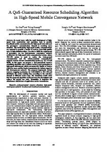
disassembled into packets. Figure 1 shows the structure of a typical OBS core router. BHP and DB of a burst use different channels, and they go through different paths in the router. The BHP is processed by an electronic or optical switch control unit (SCU). The major functions of a SCU include BHP processing, routing table look-up to determine output links of DBs, scheduling DBs on output channels, setting up the optical switch matrix to provide input-output paths for DBs, managing limited FDL buffer (queue) to avoid transmission conflicts, switching BHPs to output control channels and regenerating BHPs.
duced as a new approach for integrating IP with ATM, it has great potential to be used for traffic engineering and Diffserv QoS in IP-over-WDM. Indeed, an extension of MPLS, Multiprotocol Lambda Switching (MPλS) was proposed recently [1] to treat crossconnects as LSRs (Label Switched Routers). Naturally, OBS/OPS DWDM routers can be extended to LSRs in OBS/OPS DWDM networks. Preliminary discussion on such possibilities can be found in [15]. In this paper, we consider QoS of IP-over-WDM. In particular, we consider how to use the Diffserv model [11] to ensure QoS on DWDM OBS networks. Lack of buffers in the DWDM layer makes existing priority schemes (Diffserv QoS model) difficult. The packet classification, burst assembly and burst scheduling at ingress routers play the most important role in QoS. In this paper, we show that, with limited buffering, data channel scheduling at core routers can improve QoS considerably. We generalize an existing scheduling algorithm to include Diffserv QoS features and take advantages of MPLS. We present simulation results of the performance of an end-to-end network. These results demonstrate that our channel scheduling algorithm at core routers significantly improve QoS performance.
Fig. 1. A typical OBS core node.
II. B URST- SWITCHING DWDM N ETWORKS AND LAUC-VF CHANNEL SCHEDULING ALGORITHM
Data channel scheduling is one of the critical functions in SCU. Without loss of generality, the following assumptions are made for channel scheduling in a core router: (1) A link has k data channels Ch1 � Ch2� � � �� Chk and a control channel. This assumption simplifies our presentation. In reality, different links may have different number of channels. (2) Each output link is equipped with a scheduler, which is responsible for scheduling DBs that are switched to the link. (3) The BHPs for the DBs to be transmitted on the same output link are scheduled in the order they are received at the scheduler for that link. For simplicity, we assume that this is a linear order. (4) BHPi includes an offset field di that specifies the time interval between the transmissions of BHPi and of DBi . (5) BHPi includes a length field length i that specifies the length of DB i . Assume that length i is quantified in terms of time. (6) Each DB i is delayed by the input FDL for a fixed D time before it enters the switching matrix. This delay time is required to compensate the time for BHP processing and DB switching. (7) Recirculating FDLs support a set S L of q available FDL delay times, SL � �L1 � L2� � � �� Lq�, that can be selected by the scheduler for DBs to go through the switching matrix. (8) Slot transmission mode. In this mode, DBs are transmitted in units of slots, and BHPs are transmitted as groups, and each group is carried by one slot. Time is represented in terms of number of slots. Let tsin�BHPi � denote the time at which the first slot of BHPi is received, and let tsin �DBi � and tein �DBi � denote the receiving time of the first and last slot of DB i with respect to t sin �BHPi �, respectively, as shown in Figure 2. Clearly, t sin �DBi � � tsin�BHPi �� di and tein �DBi � � tsin�DBi �� length�DBi �. Let tsout �DBi � and teout �DBi � denote the transmission time of the first and last slot of DB i over an output channel.
An OBS DWDM network is a transport network that consists of edge routers and core routers. An edge router is located at the “edge” of the network, and it can be considered as a combination of an ingress edge router and an egress edge router. An ingress (resp. egress) edge router has a set of input (resp. output) links and a set of optical output (resp. input) links. Each optical link consists of a set of channels, each using a different wavelength. A core router is an intermediate node on a path between two edge routers. It has a set of optical input links and a set of output links. Each optical input/output link has a set of channels, each using a different wavelength. The channels of an optical link is divided into two groups, data channel group (DCG) and control channel group (CCG). A data channel (DC) is used to carry data bursts (DBs) and a control channel (CC) carries burst header packets (BHPs) and other control packets. IP packets received from the input of an ingress edge router are assembled into bursts based on egress edge router addresses and other information. Each data burst is transmitted along a transparent all-optical path. The transmissions of DBs and BHPs are separated. Each BHP, which carries the routing information, burst class type, offset time and burst length, is sent ahead of its DB by a nonnegative offset time. At each core router on the path leading to the destination egress router, a BHP is processed electronically to reconfigure the optical switch, allowing the DB that follows to pass without O/E and E/O conversions. While the initial value is set by the ingress edge router, the offset time may vary hop by hop as a BHP and its DB traverse across the network. The data bursts received at an egress (destination) edge router are
87
A gap on an output channel u, represented by g � is a maximal time interval �l � r� such that there is no DB transmitted on channel u with transmission time that overlaps with �l � r�. Clearly, a gap can be of two forms: (i) g � �0� t sout �DBx �; u�, and there does not exist any �tsout �DBy �� teout �DBy �; u� such that t sout �DBy � � tsout �DBx �, and (ii) g � �t eout �DBx �� tsout �DBy �; u�, and there does not exists �t sout �DBz �� teout �DBz �; u� SuI �i 1� such that either �t sout �DBx �� teout �DBx �� ��tsout �DBz �� teout �DBz �� �� 0/ / We use or �tsout �DBy �� teout �DBy �� � �tsout �DBz �� teout �DBz �� �� 0. SG �i 1� to denote the set of all gaps defined by schedule SI �i 1�. An algorithm, named LAUC-VF, which is the abbreviation of Latest Available Unscheduled Channel with Void Filling, the heuristics used, which was introduced in [6]. In this algorithm, a BHP reserves a wavelength for its DB based on the latest available principle, while the data burst has to be dropped if there is no available outgoing data channel after a maximum delay. A variation of LAUC-VF, which is feasible for hardware implementation was introduced in [23], is presented as follows:
DB i
�l r; u�, �
BHP i
di
t
in s(
length ( DB i )
t
BHP i )
in s(
DB i )
in
te(
DB i )
Time
Fig. 2. Relation between the receiving times of BHPi and DBi .
Then, tsout �DBi � � tsin�BHPi � � di � D � Lri and teout �DBi � � tsout �DBi � � length�DBi � � D � Lri , where Lri is an output delay time selected from SL � SL � �L0 �, with L0 � 0. We use �tsout �DBi �� teout �DBi �� to denote the transmitting time interval of DBi at a node. We say that there is a conflict between DBi and DB j if they are transmitted using the same output channel / Based and �tsout �DBi �� teout �DBi �� � �tsout �DB j �� teout �DB j �� �� 0. on tsin �BHPi �, di and length�DBi �, i � 1� 2� 3� � � �, for the same output link, the objective of channel scheduling is to assign each DBi to an output channel Ch u , 1 � u � k, and select a delay time Lri from SL for DBi such that there is no conflict between DBi and DB j , j �� i. Such a channel assignment is called a conflict-free schedule. The scheduling time (decision making time) for each �BHPi � DBi � pair should be no more than a bounded time. Due to the real-time constraints, limited look-ahead knowledge about future bursts, and the adopted cost/performance trade-off, it may not be always possible to find a conflict-free schedule for all DBs. Thus, we have the following alternative objective: find a conflict-free schedule of a maximum subset of �DBi � i � 1� 2� 3� � � �� in the least possible time. The DBs that are not scheduled successfully are considered to be dropped. Assume that BHPs arrive at the channel scheduler of an output link are BHPi , i � 1� 2� � � �, in the increasing order of i. We use set SI �i 1� � ��tsout �DBa �� teout �DBa �; ca � � 1 � a � i 1� 1 � ca � k� to represent the state of the k channels of the link at the time DB i is being scheduled, where �tsout �DBa �� teout �DBa �; ca � represents the fact that DBa is scheduled to be transmitted using channel Ch ca of output link with starting time t sout �DBa � and ending time t eout �DBa �. Since the scheduling of DB a , 1 � a � i 1, is conflict/ for free, �tsout �DBx �� teout �DBx �� � �tsout �DBy �� teout �DBy �� � 0, 1 � x� y � i 1 and x �� y. Using SI �i 1�, we define two sets, SM �i 1� and SG �i 1�, which together records all time intervals that are available for future use. For 1 � u � k, define SuI �i 1� � ��tsout �DBa �� teout �DBa �; ca � � �tsout �DBa �� teout �DBa �; ca� SI �i 1� and ca � u�. Define Eu �i 1� � max �teout �DBa � � �tsout �DBa �� teout �DBa �; ca �
/ and Eu �i 1� � 0 if S uI �i 1� � 0. / SuI �i 1�� if S uI �i 1� �� 0, Clearly, each Eu �i 1� can be used to define a semiunbounded time interval �E u �i 1�� ∞� on channel Ch u. We use SM �i 1� � ��Eu �i 1�; u� � 1 � u � k� to characterize the k semi-unbounded intervals for the k channels. ¼
LAUC-VF Algorithm input: Ti � tsin�BHPi �� di � D, length�DBi �, SM �i 1�, SG �i 1�, and SL . output: a channel number and an output delay for DB � i�, SM �i�, SG �i�. begin (a) Find a gap �l � r; f � in S G �i 1� such that Ti � l and Ti � length�DBi � � r. If this operation is not successful then goto Step (b); else do the following: ¯ Assign DBi to channel Ch f with L i � 0; ¯ SG �i� :� S G �i 1� � ��l � Ti; f �� ¯ SG �i� :� S G �i� � ��Ti � length�DBi �� r; f ��; ¯ stop. (b) Find �Eg ; g� in S M �i 1� such that Ti Eg � min�Ti Eu � Ti Eu � 0� 1 � u � k�� If this operation is not successful, then go to Step (c); else do the following: ¯ Assign DBi to channel Ch g with L ri � 0; ¯ SM �i� :� �S M �i 1� ��Eg ; g��� � ��Ti � length�DBi �; g��; ¯ SG �i� :� S G �i 1� � ��Eg� Ti ; g��; ¯ stop. (c) Find �Eh ; h� in S M �i 1� such that Eh � min�Eu � 1 � u � k�, and find La in SL such that La � min�Lb � Lb SL � Lb � Eh Ti ��. If �Eh ; h� and La are not found, goto Step (e). (d) Find �Ev ; v� in SM �i 1� such that Ti � La Ev � min�Ti � La Eu � Eu � Ti � La � 1 � u � k�� (e) Find an L p in a subset SL of SL and a gap �l � r; w� in SG �i 1� such that Ti � L p � l and Ti � length�DBi �� L p � r. If this operation is not successful then goto Step (f); else do the following: ¯ Assign DBi to channel Ch w ; ¯ SG �i� :� S G �i 1� � ��l � Ti � L p ; w�� ¯ SG �i� :� S G �i� � ��Ti � length�DBi �� L p � r; w��; ¯ stop.
¼
¼
88
(f) if Step (c) is not successful then drop DB i else do the following operations: ¯ Assign DBi to channel Ch v with L ri � La ; ¯ SM �i� :� �S M �i 1� ��Ev ; v��� � �Ti � La � length�DBi �; v�; ¯ SG �i� :� S G �i 1� � ��Ev� Ti � La ; v�. ¯ stop end of LAUC-VF The information used by LAUC-VF scheduling algorithm is the timing of forthcoming DBs, represented by S M and SG . Time is an integer variable. Due to the fixed word length, relative times must be used. For fast processing, LAUC-VF is implemented by hardware using parallel processing techniques. The implementation details of LAUC-VF are discussed in [23].
Source
Dest.
Routing path
0 10
8 9
0 3 4 5 8 10 4 5 7 9
1 2
9 8
1 2
3 6
6 7
7 5
9 8
TABLE I Traffic Descriptions.
scheme can be easily devised, but it may be infeasible for implementation. 10
III. G ENERALIZED LAUC-VF
4 0
We generalize the LAUC-VF scheduling algorithm to include Diffserv QoS features and take advantages of MPLS. We propose to partition data bursts into n classes depending on their QoS requirements. At an ingress edge router, a data burst is assembled by aggregating the packets of the same QoS class and with the same destination egress edge router. At a core router, data bursts going to the same output link will be scheduled by the scheduler associated with that link. For each link, its scheduler maintains n queues Q 1 , Q2 , ... and Qn , with Qi being used to store the BHPs of Class-i DBs in the FIFO order. For each slot, the algorithm is executed once.
8 3
5
1 6
7 9
2
Fig. 3. An end-to-end optical network.
G-LAUC-VF Algorithm begin for i � 1 to n do while Qi has BHPs belonging to the current slot do begin BHPi :� dequeue�Qi �; Use LAUC-VF algorithm to schedule DB i corresponding to BHPi end end
Now, we show the end-to-end performance of G-LAUC-VF scheduling algorithm by simulation. Considering the network topology shown in Figure 3, we assume there exist four trafficiflow groups given in Table I. Every flow group is composed of data flows of all QoS classes. Each of core nodes 5 and 7 is shared by three group of flows, and each of core nodes 3, 4, and 6 is shared by two groups of flows. Such an arrangement makes the scheduling at each core node non-trivial. Assume that each link is composed of 8 data channels and 1 control channel, and the transmission rate on each wavelength is 1Gbps. Aslo assume that a slot takes 10µs. Then, one slot can carry 1250 bytes. For simplicity, we assume that there are three classes of DBs, Class-1, Class-2 and Class-3, and their maximum data burst lengths are the same, 2 slots (i.e. 20 µs). The offset time between a BHP and its DB is a constant, 2 slots. Based on these assumptions, a control slot can certainly contain 8 BHPs, which is the maximum for a link of 8 data channels using constant burst length and constant offset time. Note that a control slot can also contain control information other than BHPs. To simulate the self-similar property of the Internet traffic, Pareto traffics [9] are generated for simulation. Data burst drops can be caused by congestion in data channels, congestion in the control channel and internal congestion in SCU. The focus of our study is on the DB drop rate due to the data channel congestion. We have generated traffic flows with
Assuming that Class-i DBs have a priority higher than that of Class- j DBs if i � j, this algorithm ensures that for those DBs whose BHPs are in Qi are scheduled before DBs whose BHPs are in Q j . Note that using MPLS simpler and faster routing, forwarding and queuing can be implemented. This Generalized LAUC-VF (G-LAUC-VF) uses LAUC-VF algorithm as a subalgorithm. Simple hardware, such as a Daisy chain for requests arbitration, can be used to manage the queues. Given that LAUC-VF can be implemented in hardware, G-LAUCVF can also be implemented in hardware. Due to the stringent real-time constraint, the simplicity of G-LAUC-VF is extremely important. Using LAUC-VF as a subalgorithm avoids the complete redesign of a new scheduling algorithm and its hardware implementation. A sophisticated queue management
89
DB rate distribution of three QoS classes as (1:1:1). Data rate specified in the following is the data rate on shared paths 4-5, 5-8, 6-7 and 7-9. Figure 4 to Figure 6 compare the drop rates of G-LAUC-VF algorithm and LAUC-VF algorithm without FDLs when the average data rate is 6Gbps and the peak rate is varying from 8Gbps to 26Gbps. While the total drop rates of these two algorithms are equal, the drop rate of Class-1 traffic is significantly reduced by the G-LAUC-VF algorithm. Table III shows the improvement percentages of the G-LAUC-VF algorithm over the original LAUC-VF algorithm for Class-1 data bursts in Figure 4. Figure 5 and Figure 6 show that the price paid for improved Class-1 drop rate is the worsened performance only for Class-3 data bursts.
0.35 LAUC−VF G−LAUC−VF 0.3
0.25
0.2
0.15
0.1
0.05
0
8
10
12
14
16 18 20
22
24
26
0.14
Fig. 6. Average drop rate of Class-3 DBs vs. peak data rate, assuming that the average data rate is 6Gbps.
LAUC−VF G−LAUC−VF 0.12
0.1
Peak Rate (Gbps)
0.08
0.06
0.04
0.02
0
8
10
12
14
16 18 20
22
24
26
Fig. 4. Average drop rate of Class-1 DBs vs. peak data rate, assuming that the average data rate is 6Gbps.
LAUC-VF
G-LAUC-VF
Drop Rate Improvement
8
0�0282
0�0
100%
10 12
0�0556 0�0599
0�0 0�0
100% 100%
14 16 18
0�0675 0�0753 0�0796
0�0007 0�0017 0�0026
98�96% 97�74% 96�73%
20 22
0�0937 0�1049
0�0063 0�0077
93�28% 92�66%
24 26
0�1168 0�1319
0�0103 0�0170
91�18% 87�11%
TABLE II Drop rate improvement of G-LAUC-VF over LAUC-VF for Class-1 DBs.
0.14 LAUC−VF G−LAUC−VF 0.12
0.1
0.08 0.2 LAUC−VF G−LAUC−VF
0.06
0.18
0.16 0.04
0.14 0.02
0
8
10
12
14
16 18 20
22
24
26
Fig. 5. Average drop rate of Class-2 DBs vs. peak data rate, assuming that the average data rate is 6Gbps.
0.12
0.1
0.08
0.06
0.04
0.02
The simulation results shown above are based on the assumption that no output buffers are used. By adding FDLs in the optical switching matrix, more flexibility is introduced to schedule DBs without conflicts. We conducted a series of simulations to look into the effects of FDLs. We assume there is a set SL of q available delay slots, separated apart by one
0
0
2
4
6
8 10 12
14
16
18
20
Fig. 7. Average drop rate of Class-1 DBs vs. max delay slots, assuming that the average data rate is 8Gbps and the peak data rate is 16Gbps.
¼
90
0.2
plicity, we assumed that all DBs have the same length, and the offset times of DBs of all classes are the same in our simulations. We believe that it is possible the QoS performance can be further improved by assigning bursts of different classes with different lengths and different offset times. We are working on new techniques and expecting that will achieve better performance.
LAUC−VF G−LAUC−VF 0.18
0.16
0.14
0.12
0.1
R EFERENCES
0.08
[1]
0.06
0.04
[2] 0.02
0
2
4
6
8 10 12
14
16
18
20
[3]
Fig. 8. Average drop rate of Class-2 DBs vs. max delay slots, assuming that the average data rate is 8Gbps and the peak data rate is 16Gbps.
[4] [5]
0.45 LAUC−VF G−LAUC−VF 0.4
[6]
0.35
0.3
[7] 0.25
[8] 0.2
[9] 0.15
[10] 0.1
0.05
0
2
4
6
8 10 12
14
16
18
20
[11] [12]
Fig. 9. Average drop rate of Class-3 DBs vs. max delay slots, assuming that the average data rate is 8Gbp and the peak data rate is 16Gbps.
[13]
slot, SL � �0� 1� � � �� MaxDelaySlots�, where MaxDelaySlots is the longest delay used in the simulation. Figure 7 to Figure 9 demonstrate the drop rates of 3 classes of traffics with MaxDelaySlots varying from 0 slots (no FDLs) to 20 slots, when the average data rate is 8Gbps and the peak data rate is 16Gbps. These experiments indicate that, for Class-1 and Class-2 traffics the performance of G-LAUC-VF is much better than than that of LAUC-VF. However, relatively speaking, adding more output FDLs will not improve much of the drop rates of traffics with higher priorities. Since FDLs are very expensive, our results indicate that using more output FDLs is not only infeasible in practice, but also may not be desirable, as far as QoS is concerned. ¼
[14] [15] [16] [17] [18] [19] [20]
IV. C ONCLUDING R EMARKS
[21]
In this paper, we propose a generalized LAUC-VF algorithm, which improves the QoS performance by prioritizing data bursts, maintaing multiple queues and utilizing limited optical buffers. Without loss of generality, we study the end-toend performance of this algorithm by generating pareto traffic flows, which are accumulated into self-similiar traffic. For sim-
[22] [23]
91
D. O. Awduche, et al., “Multi-Protocol Lambda Switching: Combining MPLS Traffic Engineering Control with Optical Crossconnect”, IETF Internet Draft, �draft-awduche-mpls-te-optical-02.txt�, Nov. 1999. R. Braden et al., “Integrated Services in the Internet Architecture”, RFC 1633, 1994. R. Braden et al., “RSVP Version 1 Functional Specification”, RFC 2205, 1997. I. Chlamtac, and G. Karmi, “Lightpath Communications: an Approach to High Bandwidth Optical WANs”, IEEE Transactions on Communications, vol. 40, pp. 1171-1182, July 1992. T. E. Stern, K. Bala, S. Jiang, and J. Sharony, ”Linear Lightwave Networks: Performance Issues”, IEEE/OSA Journal of Lightwave Technology, vol. 11, pp. 937-950, May/June, 1993 Yijun Xiong, Marc Vandenhoute and Hakki C. Cankaya, “Design and analysis of optical burst-switched networks”, SPIE Conference on AllOptical Networking: Architecture, Control and Management Issues, Vol. 3843, 1999. F. L. Faucheur, et al. “MPLS Support of Differentiated Services”, IETF Internet Draft , �draft-ietf-mpls-diff-ext-07.txt �, Aug. 2000. Andrikopoulos, I. and Pavlou, G., “Supporting Differentiated Services in MPLS Networks”, IWQoS ’99, pp. 207-215. William Stallings, High-Speed Networks: TCP/IP and ATM Design Principles, Prentice Hall, 1998. M. Yoo and C. Qiao, “Just-Enugh-Time (JET): a High Speed Protocol for Burst Traffic in Optical Networks”, Digest of IEEE/LEOS Summer Topical Meetings on Technologies for a Global Information Infrastructure, pp. 26-27, 1997. R. Braden et al., “A Framework for Differentiated Services”, Internet draft, 1999. M. Listanti, V. Eramo, and R. Sabella, “Architectural and Technological Issues for Future Optical Internet Networks”, IEEE Communications, vol. 38, no. 9, pp. 82-92, 1999. S. Verma, H. Chaskar, and R. Ravikanth, “Optical Burst Switching: A Viable Solution for Terabit Backbone”, IEEE Network, vol. 14, no. 6, pp. 48-53, Nov.-Dec. 2000. C. Qiao and M. Yoo, “Optical burst switching(OBS)-a new paradigm for an optical Internet”, J. High Speed Networks(JHSN), vol.8, no.1, pp.6984, 1999. C. Qiao, “Labeled Optical Burst Switching for IP-over-WDM Integration”, IEEE Communications, vol. 38, no. 9, pp. 104-114, 2000. C.Qiao and M. Yoo, “Choices, Features and Issues in Optical Burst Switching”, Optical Networks, vol. 1, no. 2, pp. 36-44, 2000. E. Rosen, A. Viswananthan and R. Callon, “Multiprotocol Label Switching Architecture” � IETF Internet Draft ,draft-li-mpls-igp-arch-06.txt �, Aug. 1999. J. S. Turner, “Terabit Burst Switching”, J. High Speed Networks, vol. 8, no. 1, pp. 3-16, 1999. S. Yao, B. Mukherjee, and S. Dixit, “Advances in Photonic Packet Switching: An Overview”, IEEE Communications, vol. 38, no. 2, pp. 84-94, 2000. D. Blumenthal et al., “WDM Optical IP Tag Switching with PacketRate Wavelength Conversion and Subcarrier Multiplexing Addressing”, OFC/IOOC’99. Technical Digest, vol. 3, pp. 162-164, 1999. D. Blumenthal, P. Prucnal and J. Sauer, “Photonic Packet Switches: Architectures and Experimental Implementations”, Proc. of the IEEE, vol. 82, pp. 1650-1667, 1994. D. Hunter and I. Andonovic, “Approaches to Optical Internet Packet Switching”, IEEE Communications, vol. 38, no. 9, pp. 116-122, 1999. S.Q. Zheng et al., “Hardware Implementation of Channel Scheduling Algorithms for Optical Routers with FDL buffer”, manuscript.