Hindawi Wireless Communications and Mobile Computing Volume 2018, Article ID 2850830, 15 pages https://doi.org/10.1155/2018/2850830
Research Article A Radio Propagation Model for Mixed Paths in Amazon Environments for the UHF Band L. E. C. Eras ,1 Diego K. N. da Silva ,1 Fabr-cio B. Barros,1 Lu-s M. Correia,2 and G. P. S. Cavalcante1 1 2
Federal University of Par´a, Bel´em, Par´a, Brazil IST/INESC-ID, University of Lisbon, Lisbon, Portugal
Correspondence should be addressed to L. E. C. Eras;
[email protected] Received 11 June 2018; Revised 19 September 2018; Accepted 30 September 2018; Published 1 November 2018 Academic Editor: Ke Guan Copyright © 2018 L. E. C. Eras et al. This is an open access article distributed under the Creative Commons Attribution License, which permits unrestricted use, distribution, and reproduction in any medium, provided the original work is properly cited. This paper presents a radio propagation model for the UHF band that is designed for an outdoor scenario in the Amazon region of Brazil and comprises city, water, and forest environments. The model is designed for the Mobile and Home Digital Television (MDTV and H-DTV) services. In the case of M-DTV, the electric field is calculated at user height, while for H-DTV it considers a fixed antenna on houses roofs. The field calculation is based on Geometrical Optics (GO) and the Uniform Theory of Diffraction (UTD). The results for M-DTV show a good agreement with measurement data in an Amazonian city (Bel´em) for 521 MHz. Different parameters of the proposed model are analyzed: the transition zone city-water, the level of water, the incidence angle in the forest, and electrical parameters for forest. Finally, the comparison that was made between the electric fields for H-DTV and M-DTV shows a difference of up to 19 dB.
1. Introduction Brazil has 62% of the Amazon region [1]. This type of scenario is always a challenge for telecommunication systems, due to its tropical weather and dense forest. It is generally formed of wide rivers and islands with dense forest, with cities and inhabited areas only being found on the borders [2]. The rivers are important for the economic development of Amazonian cities, because they are used mainly for commerce and tourism. One widely extended service of telecommunications in Brazil is television (TV), which is in 90% of the residences. Currently, Brazilian Digital Television (DTV) covers 46% of the population, i.e., 89 million people, and is based on the Japanese standard, called Integrated System Digital Broadcasting (ISDB-T) [3]. The spectrum for DTV is allocated in [470, 806] MHz. According to the Brazilian Association of Technical Standards (ABNT), there are two types of receivers in the ABNT NBR154604 norm [4]: one segment and full segment. One segment receivers have screens smaller than 7 inches and a bandwidth of 0.43 MHz, whereas the full segment are meant for fixed and mobile services, with a bandwidth of 5.7 MHz.
One can usually consider also two types of DTV regarding the way that people watch TV: mobile (M-DTV) and fixed/home (H-DTV). In the former, users have mobile terminals, while in the latter the antennas are positioned on the roofs of houses. Several scenarios have been studied for MDTV concerning signal propagation, such as urban environment [5], under ducts [6], mixed land-sea paths [7], and indoor [8]. For H-DTV, there are also studies for urban scenarios [9] and indoor environments [10]. Furthermore, as the UHF band is also used in mobile communications, there are studies of the coexistence of DTV with mobile communications [11] and for the fifth generation avoiding interference for DTV [12]. This work focuses on outdoor radio propagation for MDTV and H-DTV in a mixed path. In the literature, most of the studies on radio propagation are designed for land-sea or city-forest scenarios. In the case of land-sea scenario, the models are for low frequencies in the HF [13, 14] and MF bands [15–17] for vertical polarization. ITU-R Recommendation, P.1546 [18], addresses the UHF band, but it does not differentiate if the first path is over land or sea, unlike the Okumura model [19] that establishes the correction for
2 a mixed path by determining whether the first path is over water or land; even when Okumura and ITU-R P.1546 can be applied in a land-water path, they do not consider obstacles in the transition zone from land to water. For a mixed city-forest path, [20, 21] address mobile services, where the loss caused by obstacles around the receiver is calculated using knife-edge diffraction. Furthermore, the loss caused by a forest can be taken as in ITU-R Recommendation P.833 [22], which gives an attenuation factor for the type of forest of some countries, including Brazil, but it does not apply to the Amazon region. Models for radio propagation in the Amazon region involve conducting studies inside the forest [23], where dyadic green functions were applied by using four layers, for vertical polarization: air, treetop, trunk, and land. Another study [24] relies on parabolic equations but has limitations for large propagation angles. A less studied scenario for mixed path involves mixed land-river path as in [25], which analyses propagation over water when there is the presence of obstacles, like buildings and bridges; however, this study does not take account of the interaction between diffraction from a city and reflection over water and only provides results for distances longer than 1km. In response to the need to design a propagation model for mixed paths in the Amazon region, this paper proposes a model based on Geometrical Optics (GO) and the Uniform Theory of Diffraction (UTD). Earlier works have implemented reflection and diffraction for urban scenarios, such as in the models designed by Ikegami [26] and Walfish-Bertoni [27]. The former considers grazing knife diffraction and the latter models buildings as several half-screens edges, with the combination of the two being the COST231 Walfish-Ikegami model [28], duly assessed in Europe. The proposed model is called Mixed Path and, unlike those currently being employed, is designed for a scenario formed by a mixed city-water-forest-water-forest path, for M-DTV and H-DTV. It uses UTD, besides GO, because it is more accurate than knife diffraction when obstacles have finite conductivity [29]. It has the number of rays enough to describe the various environments, by including reflection, diffraction, and refraction/transmission. Therefore, Mixed Path implements a 2D scenario which reduces the computational complexity and the number of rays and hence is able to make a good estimate, for Digital Television. In the literature, the case studies that apply 3D ray tracing are generally designed for small urban environments and for a transmitter lower than the obstacles around it, where the multiples rays are more significant as shown in [30, 31]. Additionally, Mixed Path model describes the transition zone between city and water. This highlights the interaction of diffracted rays caused for the city and reflected rays over water, which might be either a significant constructive or destructive addition, especially when the receiver over the water is less than 1 km from the city. A refracted/transmitted ray from air to forest and forest to air (based on the features of the Amazon forest) is calculated for the forest by taking account of the absorption it causes. An environmental correction factor is added to calculate the electric field over water. Earlier studies [13, 25] noted that
Wireless Communications and Mobile Computing a mixed path (land-water) presents an additional attenuation compared with propagation only over water. For this reason, [13] introduces a mixed media propagation factor, but it does not consider buildings around the transmitter, and in [25] the equation of free space is replaced by Okumura formulation. The Mixed Path model for M-DTV has been validated by measurement data in Bel´em of Par´a. Additionally, it has been compared with different models of literature, such us Free Space [32], Okumura-Hata [19, 33], ITU-R P.1546 [18], and Walfish-Ikegami [28] which is only designed for city pathways. H-DTV is compared with ITU-R P.1546 for rural areas, because it is quite similar to the proposed environment of H-DTV, which always has line of sight. This paper is organized in seven sections, besides the current one. Section 2 describes the scenario under study, and Section 3 shows the application of the model. Section 4 presents an analysis of the model parameters, Section 5 shows the measurement campaign, and Section 6 analyzes the results. Finally, Section 7 summarizes the conclusions, and an Appendix contains the detailed equations.
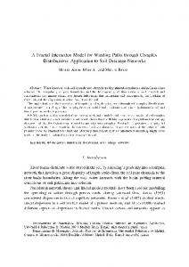
2. Model Scenario The Amazon region is formed by various environments such as city, river, and forest. Broadcast transmission services have to be planned for the benefit of the people who use the rivers for commerce or tourism and also who live behind the dense forest; thus, the Mixed Path model is designed for both MDTV and H-DTV. The scenario is illustrated in Figure 1, with the different regions denominated as City, Water1, Forest1, Water2, and Forest2. In the scenario for M-DTV, the transmitter is in city and it is higher than the obstacles surrounding it. Thus, a 2D solution has been found to reduce computational complexity and the number of rays but without losing the ability to make an optimal electric field estimation. The parameters defined in Figure 1 are described in what follows. The transmitter antenna height, ℎ𝑇, is always higher than the receiver antenna, which can either be for M-DTV, ℎ𝑀𝑅, or for H-DTV, ℎ𝐻𝑅 ; the latter corresponds to the one of the antenna, ℎ𝐴, on the top of the building, which can be either in the city, ℎ𝐵𝐶, or on the border of the river, ℎ𝐵𝐹. The height of ground level of the city, ℎ𝐺𝐶, is considered to be higher than the one of the forest, ℎ𝐺𝐹; the forest height, ℎ𝐹 , is taken as the height of the trees. All these heights are taken as average values. Horizontal distances illustrated in Figure 1 are as follows: the distance between transmitter and receiver, 𝑑𝑇𝑅 , the distance between the transmitter and the last point of city denominated the width of the city, 𝑊𝐶 . The width of the river depends on the specific branch being considered, i.e., 𝑊𝑊1 and 𝑊𝑊2 , and the same applies to the forest, 𝑊𝐹1 and 𝑊𝐹2 . Finally, the street and building widths, 𝑊𝑆 and 𝑊𝐵 , are obtained from a top view, by drawing a line from the transmitter to the receiver, hence defining an angle 𝜑 with the street or the building, which is always lower than, or equal to, 90∘ .
3. Description of the Model 3.1. Rays Used by Mixed Path Model. The model includes the interaction of the following rays: line of sight, reflection,
Wireless Communications and Mobile Computing
City (C)
3
Water 1 (W1)
Forest 1 (F1)
Water 2 (W2)
Forest 2 (F2)
B!
B4
B(2 B"#
B-2 B&
B'#
B"& WM /2 WM /2 WM
7 "
>42 7#
B'&
7" /2 7" /2
771
7&1
772
7&2
Figure 1: Scenario for Mixed Path model for the services of M-DTV and H-DTV.
Table 1: Rays used for the mixed path model. 𝐸𝐿𝑂𝑆 𝐸𝑟ℎ 𝐸𝑟V 𝐸𝑑− 𝐸𝑑+ 𝐸𝑑−𝑟ℎ 𝐸𝑑+𝑟ℎ 𝐸𝑑−𝑟V 𝐸𝑑+𝑟V 𝐸𝑡
Line of sight. Reflection on a horizontal surface. Reflection on a vertical surface. Diffraction on the left. Diffraction on the right. Diffraction on the left, reflection on a horizontal surface. Diffraction on the right, reflection on a horizontal surface Diffraction on the left, reflection on a vertical surface Diffraction on the right, reflection on a vertical surface Refraction/Transmission through the forest.
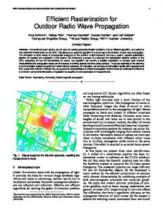
diffraction, diffraction-reflection, and refraction/transmission. These rays are illustrated in Figure 2 (not at scale) and Table 1 shows all the possible rays that can exist to calculate the total electric field for M-DTV and H-DTV. The notation adopted in Figure 2 is as follows. In the City, 𝑏 represents the point of incidence for diffraction, and 𝑝𝑟 is the point of incidence for reflection. The angle formed with the direct ray is 𝜃𝐷, and the grazing angles for a reflected ray on a vertical or horizontal surface are 𝜃𝑟V and 𝜃𝑟ℎ , respectively. The angles of incidence and refraction/transmission in the forest are Ψ𝑖𝑎𝐹 , Ψ𝑡𝑎𝐹 for air-forest and Ψ𝑖𝐹𝑎 , Ψ𝑡𝐹𝑎 for forest-air. The point of incidence for air-forest refraction/transmission is 𝑝𝑡 and 𝑛 is the point for forest-air refraction/transmission. The direct distance (different from 𝑑𝑇𝑅 , taken over ground) from transmitter to the receiver is 𝑅𝑇𝑅 . In the City-Water1-Forest1-Water2-Forest2 case, the line of sight and reflected rays exist if 60% of the first Fresnel ellipsoid is unobstructed. In the other cases, there are only diffracted rays, with the exception of Water2 where there is only the transmitted ray.
With regard to M-DTV, the maximum number of rays for each path is 8 for City, 4 for Water1, and 3 for Water2; for HDTV, this count is 3 for City (direct, reflected on the rooftop and diffracted on the building edge), while for the houses on the border of the river after Water1 and Water2, there is 1 reflected ray over the river. 3.2. General Equations for the Mixed Path Model. The electric field for each ray that contributes to the total electric field at the receiver antenna is calculated on the basis of the following formulas. (1) Line of Sight. The electric field with line of sight, ELOS , is [32] 𝐸𝐿𝑂𝑆 (𝑅𝑇𝑅 ) =
√30𝑃𝑇 𝐺𝑇 −𝑗𝑘𝑅𝑇𝑅 , 𝑒 𝑅𝑇𝑅 √𝐿
(1)
where (i) 𝑃𝑇 : Transmission Power (ii) 𝐺𝑇: Transmitter antenna gain (iii) 𝐿: Loss for connectors, cable, etc. (iv) 𝑘: Free space propagation constant [34]. (2) Reflection. The reflecting surfaces are horizontal or vertical, planar, and smooth. Horizontal surfaces are water, streets, and rooftops and a vertical surface is the wall of a building. The coefficient of reflection, Γ, [35] can have horizontal or vertical polarization and the electric parameters are given by the reflecting surface. The reflected electric field, 𝐸𝑟 , is 𝐸𝑟 (𝑅𝑇𝑅 ) = 𝐸𝐿𝑂𝑆 (𝑅𝑇𝑝𝑟 )
𝑅𝑇𝑝𝑟 𝑅𝑇𝑝𝑟 + 𝑅𝑝𝑟 𝑅
Γ𝑒−𝑗𝑘𝑅𝑝𝑟 𝑅 ,
(2)
4
Wireless Communications and Mobile Computing City (C)
T
Forest 1 (F1)
Water 1 (W1)
Water 2 (W2)
Forest 2 (F2)
2 42
b
ΨC;&
LP
Jt
JL
JL
g
$
j
ΨC&;
ΨN;&
R LB
z
n
ΨN&;
LB
JL
JL
Ed-rh Ed+rh Ed-rv Ed+rv Et
ELOS Erh Erv EdEd+
Figure 2: Rays used in Mixed Path for calculation of total electric field for M-DTV and H-DTV.
where
𝑑𝑝𝑟 𝑗 =
(i) 𝐸𝐿𝑂𝑆 (𝑅𝑇𝑝𝑟 ): Incidence electric field in 𝑝𝑟 (ii) 𝑅𝑇𝑝𝑟 : Distance between transmitter and 𝑝𝑟 (iii) 𝑅𝑝𝑟𝑅 : Distance between 𝑝𝑟 and the receiver (iv) Γ: Reflection coefficient. For the service of M-DTV in City, not all the incident rays for reflection reach a wall of a building. In determining which rays are reflected in the wall, ℎ𝑝𝑟𝑔 has to be lower than ℎ𝐵𝐶, where ℎ𝑝𝑟 𝑔 is the height between 𝑝𝑟 and 𝑔, shown in Figure 2. The following equation is used for ℎ𝑝𝑟𝑔 : ℎ𝑝𝑟 𝑔 = (
𝑊𝑠 ) + ℎ𝑀𝑅. 2 tan 𝜃𝑟V
(3)
The parameters of (3) were described in Section 2. In the case of Water, as in City, not all the incidence rays reach the reflecting surface. To know which rays are reflected over the Water1, the distance between 𝑧 and 𝑝𝑟 , 𝑑𝑧𝑝𝑟 , shown in Figure 2 has to be greater than 𝑊𝐶 shown in Figure 1. For Water2, 𝑑𝑧𝑝𝑟 has to be greater than distance formed by the addition of 𝑊𝐶 , 𝑊𝑤1 , and 𝑊𝐹1 , shown in Figure 1. For the service of H-DTV, to determine the rays that are reflected on the rooftops of the houses, the distance 𝑑𝑝𝑟 𝑗 between 𝑝𝑟 and the base of the receiver 𝑗, illustrated in Figure 2, has to be lower than 𝑊𝐵 /2 shown in Figure 1. The equation for, 𝑑𝑝𝑟 𝑗 , is
ℎ𝐴 . tan 𝜃𝑟ℎ
(4)
(3) Diffraction. In the absence of line of sight, the diffracted rays are the main contributors to the total electric field. Diffraction is calculated using UTD, and the diffraction coefficients are given in [34]. Mixed path model uses a 2D UTD that has a perpendicular incidence angle of diffraction, and thus the electrical field can be propagated in the 𝑥, 𝑦 coordinates. When the incident ray reaches the point of diffraction, the diffracted rays propagate along a disk. On the other hand, a 3D UTD will form a diffraction cone [34], which means more diffracted rays can be produced. Previous studies with 3D ray tracing can create a detailed urban environment that includes buildings of different heights, and when the transmitter is lower than the buildings, forward and backward diffraction are significant [30]. In [31], it is also mentioned that more diffracted rays are significant when the transmitter is small; however, the cases of studies are designed for short distances. The scenario for the Mixed Path model has buildings of a uniform size and a transmitter antenna that is higher. The buildings on the left and on the right of the reception point produce the most significant diffracted rays for City since these are the nearest buildings. When the receiver over the water is far from the city, it is not necessary to have many diffracted rays, because there are no big obstacles over the water, and thus a 2D UTD can be used.
Wireless Communications and Mobile Computing
5
This model uses 𝑛 = 1.5, for straight diffraction surfaces. The Mixed Path model takes into account diffraction on the left, 𝐸𝑑− , and on the right, 𝐸𝑑+ . The equation for the diffracted field, 𝐸𝑑 , is 𝐸𝑑 (𝑅𝑇𝑅 ) = 𝐸𝐿𝑂𝑆 (𝑅𝑇𝑏 ) √
𝑅𝑇𝑏 𝐷𝑒−𝑗𝑘𝑅𝑏𝑅 , 𝑅𝑏𝑅 (𝑅𝑇𝑏 + 𝑅𝑏𝑅 )
(5)
where (i) 𝐸𝐿𝑂𝑆 (𝑅𝑇𝑏 ): Electric field at the point of incidence 𝑏 (ii) 𝑅𝑇𝑏 : Incidence distance between the transmitter and 𝑏 (iii) 𝑅𝑏𝑅 : Diffraction distance between 𝑏 and the receiver (iv) 𝐷: Diffraction coefficient. Additionally, another important ray is the diffractedreflected. In the transition zone from the city to the river, magnitude and phase of diffracted and diffracted-reflected rays modify the total electric field over Water1. The electric field diffracted-reflected, 𝐸𝑑𝑟 , is given by the following equation [34, 36]: 𝐸𝑑𝑟 (𝑅𝑝𝑟 𝑅 ) = 𝐸𝑑 (𝑅𝑏𝑝𝑟 )
√𝑅𝑇𝑏 𝑅𝑝𝑟 𝑅 (𝑅𝑇𝑏 +𝑅𝑝𝑟 𝑅 ) √𝑅𝑇𝑏 𝑅𝑝𝑟 𝑅 (𝑅𝑇𝑏 +𝑅𝑝𝑟 𝑅 ) + 𝑅𝑝𝑟 𝑅
Γ𝑒−𝑗𝑘𝑅𝑝𝑟 𝑅 ,
(6)
where (i) (ii) (iii) (iv)
𝐸𝑑 (𝑅𝑏𝑝𝑟 ): Incidence diffracted electric field in b 𝑅𝑇𝑏 : Distance between transmitter and b 𝑅𝑏𝑝𝑟 : Distance between 𝑏 and 𝑝𝑟 𝑅𝑝𝑟𝑅 : Distance between𝑝𝑟 and the receiver.
+ 𝐸𝑑+ (𝑅𝑇𝑅 ) + 𝐸𝑑−𝑟V (𝑅𝑇𝑅 ) + 𝐸𝑑−𝑟ℎ (𝑅𝑇𝑅 ) + 𝐸𝑑+𝑟V (𝑅𝑇𝑅 )
𝐸𝑡 (𝑅𝑇𝑅 ) 𝑅𝑇𝑝𝑡 𝑅𝑇𝑝𝑡 + 𝑅𝑝𝑡 𝑛 + 𝑅𝑛𝑅
𝜏𝑎𝑓 𝜏𝑓𝑎 𝑒−𝑗𝑘𝑅𝑛𝑅 ,
where (i) (ii) (iii) (iv) (v) (vi)
𝐸𝐿𝑂𝑆 (𝑅𝑇𝑝𝑡 ): Incidence electric field in 𝑝𝑡 𝑅𝑇𝑝𝑡 : Distance between transmitter and 𝑝𝑡 𝑅𝑝𝑡𝑛 : Distance inside the forest between 𝑝𝑡 and 𝑛 𝑅𝑛𝑅: Distance between 𝑛 and the receiver 𝜏𝑎𝑓 : Refraction/transmission coefficient air-forest 𝜏𝑓𝑎 : Refraction/transmission coefficient forest-air.
3.4. Total Electric Field for City for M-DTV. The City path can have eight main rays to calculate the total electric field that arrives at the receiver, as the expression in (8) shows. The total electric field for City, 𝐸Σ𝑀𝐶, is 𝐸Σ𝑀𝐶 (𝑅𝑇𝑅 ) = 𝐸𝐿𝑂𝑆 (𝑅𝑇𝑅 ) + 𝐸𝑟V (𝑅𝑇𝑅 ) + 𝐸𝑑− (𝑅𝑇𝑅 )
(4) Refraction/Transmission. Two refractions/transmissions are employed in the forest: the first is air-forest and the second is forest-air. The forest is a lossy medium; the angle of refractions/transmission will be complex if Snell’s law is applied [32]. To ensure a physical coherence, the real angles for these two refraction/transmissions are calculated on the basis of [32, 37] and a detailed description is given in Appendix A ((A.23)-(A.37)). The equation for the electric refracted/transmitted field [32], 𝐸𝑡 , is
= 𝐸𝐿𝑂𝑆 (𝑅𝑇𝑝𝑡 )
3.3. Methodology for Total Electric Field in Each Path. As mentioned in Section 3, with regard to M-DTV, each path has a different number of rays. However, in some cases, not all the rays contribute in the total electric field at the receiver. The direct and reflected rays are conditioned, because if there is an obstacle between the transmitter and the receiver, they are unable to reach the receiver. The Mixed Path model uses the Fresnel parameter to determine whether or not the reflected ray will arrive at the receiver. The Fresnel parameter, V [35], indicates whether or not the transmitter and the receiver have a line of sight. As a result, the values of V that are lower than -0.78 indicate that there is line of sight between the transmitter and receiver. This is because the first Fresnel zone is unobstructed 60%. In the case of M-DTV, the direct and reflected rays that contribute to the total electric field are identified using two sets of Fresnel parameters for each path. The first Fresnel parameters are for the direct rays, V𝐶𝐷, V𝑊1𝐷 , and V𝑊2𝐷 and the second Fresnel parameters are for the reflected rays V𝐶𝑟 ,V𝑊1𝑟 , and V𝑊2𝑟 , which are outlined in detail in Appendix A. With regard to H-DTV, in Forest1 and Forest2, the reflected rays over the water might be obstructed by the houses alongside the river. The Fresnel parameters for reflected rays are V𝐻𝐹1𝑟 and V𝐻𝐹2𝑟 , described in Appendix A.
(7)
(8)
+ 𝐸𝑑+𝑟ℎ (𝑅𝑇𝑅 ) . The parameters in (8) are the electric fields described earlier in Table 1 and by (1), (2), (5), and (6). However, expression (8) can be altered, and the values of the direct ray, reflected ray, or both can be zero. In the case of direct ray, when V𝐶𝐷 has values greater than -0.78, the direct ray does not arrive at the receiver, and, as a result, it is zero. Furthermore, the reflected ray might be zero when one of the two conditions to be added in (8) is not accomplished. These two conditions are as follows: (i) given in Section 3, the incident ray has to reach the reflecting surface and (ii) the values for V𝐶𝑟 must be lower than -0.78. 3.5. Total Electric Field for Water1 for M-DTV. The second path for M-DTV is Water1. In this model, the transmitter is in the city, and thus the electric field calculated over the water is calculated as a mixed path. Different techniques are applied for mixed paths, as shown in ITU-R 1546 [18, 25]. The Mixed Path model adds an environmental correction factor, so that the attenuation caused by City in the electric field over Water1 can be incorporated. Then, first of all, the correction factor is calculated. After this, it is added to electric field calculated for the water considering the obstacles in
6
Wireless Communications and Mobile Computing
the border City-Water1. The environmental correction factor, (𝐶𝑊1 ), is given by the following equation: 𝐶𝑊1 (𝑊𝐶) = 𝐸Σ𝑀𝐶 (𝑊𝐶) − 𝐸𝐿𝑂𝑆 (𝑊𝐶) .
(9)
The electric field over Water1 without considering the attenuation from City, 𝐸Σ𝑀𝑊1 , is given by 𝐸Σ𝑀𝑊1 (𝑅𝑇𝑅 ) = 𝐸𝐿𝑂𝑆 (𝑅𝑇𝑅 ) + 𝐸𝑟ℎ (𝑅𝑇𝑅 ) + 𝐸𝑑− (𝑅𝑇𝑅 ) + 𝐸𝑑−𝑟ℎ (𝑅𝑇𝑅 ) .
(10)
(11)
The electric fields of (10) were described earlier in Table 1 and by (1), (2), (5), and (6). Equation (10) can be modified the same as in (8): direct ray is zero when V𝑊1𝐷 is greater than -0.78. The reflected ray is zero when the incident ray does not reach the water surface or V𝑊1𝑟 is greater than -0.78. 3.6. Total Electric Field for Water2 for M-DTV. Following the methodology for Water1, the environmental correction factor for Water2 (𝐶𝑊2 )is 𝐶𝑊2 (𝑊𝐶+ 𝑊𝑊1 ) = 𝐶𝑊1 (𝑊𝐶) + 𝐸Σ𝑀𝑊1 (𝑊𝐶+ 𝑊𝑊1 ) − 𝐸𝐿𝑂𝑆 ((𝑊𝐶+ 𝑊𝑊1 )) .
(12)
In (12), 𝐸Σ𝑀𝑊1 is limited to have a maximum value, the value of free space. The total electric field, 𝐸𝑀𝑊2 , for Water2, without including the environmental correction factor, is 𝐸Σ𝑀𝑊2 (𝑅𝑇𝑅 ) = 𝐸𝐿𝑂𝑆 (𝑅𝑇𝑅 ) + 𝐸𝑟V (𝑅𝑇𝑅 ) + 𝐸𝑡 (𝑅𝑇𝑅 ) .
(13)
The electric fields in (13) were described earlier in Table 1 and in (1), (2), and (7). The total electric field for the mixed path in Water2 is 𝐸𝑀𝑃𝑊2 = 𝐸Σ𝑀𝑊2 (𝑅𝑇𝑅 ) + 𝐶𝑊2 (𝑊𝐶+ 𝑊𝑊1 ) .
(14)
In (13), the direct ray and reflected ray can be zero. The direct ray is zero when the values of V𝑊2𝐷 are greater than 0.78. Additionally, the reflected ray is zero when the reflected ray does not reach the reflecting surface, in this case water, or when the values of V𝑊2𝐷 are greater than -0.78. 3.7. Total Electric Field for H-DTV in City. In the case of HDTV, for City path, the total electric field, 𝐸Σ𝐻𝐶 , is given by 𝐸Σ𝐻𝐶 (𝑅𝑇𝑅 ) = 𝐸𝐿𝑂𝑆 (𝑅𝑇𝑅 ) + 𝐸𝑟ℎ (𝑅𝑇𝑅 ) + 𝐸𝑑− (𝑅𝑇𝑅 ) .
𝐸Σ𝐻𝐹1.2 (𝑅𝑇𝑅 ) = 𝐸𝐿𝑂𝑆 (𝑅𝑇𝑅 ) + 𝐸𝑟ℎ𝐻 (𝑅𝑇𝑅 ) + 𝐸𝑟ℎ𝑊1,2 (𝑅𝑇𝑅 ) + 𝐸𝑑− (𝑅𝑇𝑅 ) ,
(16)
where (i) 𝐸𝑟ℎ𝐻(𝑅𝑇𝑅 ): Reflective field over the roof of the houses (ii) 𝐸𝑟ℎ𝑊1,2 (𝑅𝑇𝑅 ): Reflective field over Water1 or Water2.
Hence, the equation for mixed path City-Water1 is 𝐸𝑀𝑃𝑊1= 𝐸Σ𝑀𝑊1 (𝑅𝑇𝑅 ) + 𝐶𝑊1 (𝑊𝐶) .
3.8. Total Electric Field for H-DTV in Houses on the Border of Forest1 and Forest2. With regard to houses located on the border of the forest path according to Figure 1, the correction factor is not been added because it is considered to be line of sight in this situation. The total electric field, 𝐸Σ𝐻𝐹1.2 , for Forest1 and Forest2 is
(15)
The electric fields in (15) were described earlier in Table 1 and in (1), (2), and (5). In (15), the reflected ray can be zero if the incident ray of reflection does not reach the roof, as mentioned in Section 3.
The electric fields in (16) were described earlier in Table 1 and in (1), (2), and (5). Furthermore, in (16), the reflected field can be zero if V𝐻𝐹1𝑟 is greater than -0.78 for Forest1, and in the case of Forest2, the reflected ray is zero when V𝐻𝐹2𝑟 is greater than -0.78.
4. Analysis of the Mixed Path Parameters The Mixed Path model predicts the electric field in an Amazon environment, where the signal interacts with different electrical parameters from city, water, and forest. Furthermore, the receivers are over ground level, over water, over rooftops, and both in front of and behind forest. Three parameters were analyzed for M-DTV: (a) the transition zone City-Water1, for the receiver over Water1, (b) the electrical parameters of the forest, and (c) the incidence angle at the forest. The level of the river is also analyzed for H-DTIV. 4.1. Transition Zone City-Water1. The electric field which is calculated with a receiver at different distances over Water1 is shown in Figure 3. The distances over the water are given by (A.13), from Appendix A. The buildings in the transition zone City-Water1 are 15 m in height. The city width is 1.1 km. The other parameters are the same as in Appendix B. Figure 3 illustrates how the receiver over Water1 leaves the shadow zone caused by the City, where there are only diffracted rays of up to 0.28 km. After this, an increase of the signal is observed because the ray with line of sight is added. Finally, after a distance of 0.39 km, reflected ray is also added. The red line indicates a diffracted ray only up to 0.39 km, and after this distance, only direct and reflected rays are used. The blue line indicates a diffracted ray in all the points of reception. In Figure 3, an arrow indicates the unobstructed third zone of Fresnel from a distance of 0.8 km. This means that, from 0.8 km, the blue and the red lines have almost the same values because the direct ray and the reflected ray are the main contributors to the total electric field. Additionally, at 0.6 km, the red line shows a destructive addition of reflected ray and direct ray. At the same distance, the blue line shows a less pronounced attenuation because it is affected by the diffracted rays from the city. The transition zone city-river shows that signal over the water is attenuated, especially at a distance less than 1 km from the city.
Wireless Communications and Mobile Computing
7 95
115 110
90
100 95 90 3rd Fresnel Zone 100% free
85 80 75 70 65 60
Electric Field [dBuV/m]
Electric Field [dBuV/m]
105
80 75 70
Destructive addition of reflected and direct rays 10−1
85
65 60
100 Distance over the water [km] Diffraction in all reception points Diffraction until the first Fresnel zone is free
65
70 75 80 Incidence angle [∘ ]
85
90
Figure 4: Electric field versus forest incidence angle.
Figure 3: Transition zone City-Water1: Electric field versus distance only over the water. 114
4.3. Level of the River. The river level was analyzed for HDTV. The receiver has a fixed position on the border of Forest1 at a distance of 5.01 km from the transmitter. As the maximum level of the river is 0 m, negative numbers were used in Figure 5 to represent the decreasing river level. The electric field at a 0 m river level is 113 dB𝜇V/m, 14 dB more than when the river level decreases by 3 m. The height from the ground of the City and Forest1 have to be increased to estimate the level river in this model.
Electric Field [dBuV/m]
112
4.2. Electrical Parameters of the Forest and Incidence Angle for Refraction/Transmission. The electrical parameters for dense, sparse, and medium forest have been studied for MDTV, and these parameters are in [21]. The electric field was calculated varying only the electrical parameters with a receiver located at the same place over Water2. The width of forest is 2 km. The width of City is 1km and the width of Water1 is 1 km. The other parameters are shown in Appendix B. The results showed that the electric field for a sparse forest is 84 dB𝜇V/m, for a median forest is 74 dB𝜇V/m, and for a thick forest is 72 dB𝜇V/m. There is a difference of 12 dB between a thick and a sparse forest and 2 dB between a medium and a thick forest. Thus, the electric field for a thick forest is the lowest. The last parameters for M-DTV are the angles of incidence, forest-air, 𝜓𝑖𝑎𝑓 , illustrated in Figure 2. The receiver is over Water2 and the point of incidence in the forest, 𝑝𝑡 , shown in Figure 2 is the same for all the angles evaluated. Figure 4 shows that electric field decreases when there is an increase in the incidence angle air-forest. Angles lower than 62 degrees are not taken into account because the refraction/transmission forest-air does not occur. At 89 degrees, the electric field is 30 dB less than that at 63 degrees.
110 108 106 104 102 100 98
−3
−2.5
−2 −1.5 −1 River level [m]
−0.5
0
Figure 5: Electric field versus river level.
5. Measurement Campaign Two measurement campaigns were carried out to validate Mixed Path model. The first was conducted over Belem city at distances of up to 20 km. The second was over the water and some points in Belem City. These two measurement campaigns are detailed next. 5.1. Measurement Campaign in Belem City. The measurement data for the city were collected in Belem, Par´a, with the assistance of a technical team from a local TV station for distances up to 20 km. The transmission central frequency was 521 MHz, with a bandwidth of 6 MHz. There were 37 reception points over the city. The height of the receiver antenna was 4 m and the height of the transmitter antenna was 114.58 m, both above ground level. The Effective Isotropic Radiated Power (EIRP)
8
Wireless Communications and Mobile Computing Table 2: RMS error for city-MDTV.
1.6 km
Mixed Path 6.17
RMS Error [dB] for City-MDTV Okumura WalfishHata Ikegami 10.7 8.8
ITU-R P.1546 7.0
2.6 km
5 km
Figure 6: Radials of measurement data over water and city near the river.
was 49.32 dB. The antenna gain with regard to a reference isotropic antenna was expressed in units referred to as dBi. Thus, the receiver antenna gain was 5 dBi and the transmitter antenna gain was 13.25 dBi. Both the transmitter and receiver antennas had horizontal polarization and were omnidirectional. Power reception was collected with an ANRITSU spectrum analyzer, the geographic coordinates were measured with a GARMIN’S GPS 12 MAP Personal Navigator𝑇𝑀 . The city of Belem can be characterized as a suburban city because it has some high buildings, near the transmitter placement, and also a residential area. 5.2. The Measurement Campaign over Water. Data over the water was collected with a Site Master ANRITSU S332E that used the same transmitter in the City. The receiver antenna gain was 2.15 dBi and was mounted on a ship (called Curupira) with a height of 5 m above sea level. The measurements over water were carried out continuously. The receiver antenna was rotated to obtain the maximum power reception. A total of 256 points were collected and distributed in three radials shown in Figure 6, and 16 of them were collected behind the forest. Additionally, 27 reception points were collected in City near the river, illustrated in Figure 6. The receiver antenna was 4 m in height over the ground level. From Figure 6, it can be seen that the radials have different paths that include city, water, and forest. By having these features, Amazon cities are unique scenarios. Figure 7(a) shows the City-Water1 scenario where the river has a smooth surface, while in Figure 7(b) the forest and houses can be observed on the border of the river. Figures 7(c) and 7(d) illustrate the reception devices above the water.
6. Results 6.1. Results for M-DTV in the City. This section compares the measured and predicted results. The radio propagation models are Okumura Hata, Walfish-Ikegami, the Recommendation ITU-R. P.1546, and the Mixed Path model. The parameters for the simulations are given in Appendix B. The measured data were organized in annuli of 200 m, in order to have a more uniform scenario.
The assessments of the results of the different propagation models for the City are compared with the measurement data, through the calculations of RMSE. In Table 2, the Mixed Path model has the lowest RMSE because, unlike the other models, it includes features of Belem city, such as the height of the buildings and the electrical parameters. 6.2. Results for M-DTV over Water. The simulation data are illustrated in two procedures, radials and annuli, in Figures 8 and 9, respectively. Annuli cannot be employed for data after the forest, because the width of forest is different for each radial, as shown in Figures 8(a) and 8(b). The results for the predicted electric field and measured data are illustrated in Figure 8(a) for Radial 2 and in Figure 8(b) for Radial 3. In Figures 8(a) and 8(b), for distances up to 2.6 km, the signal shows significant increasing or attenuation because it is the transition zone city-water. However, for distances greater than 2.6 km, the signal has a soft decreasing. The current radio propagation models, such as OkumuraHata and ITU-R P.1546, do not predict the signal in the transition zone city-water. In contrast, as shown in Figure 8, the Mixed Path model is in closest agreement with the measurement data in the transition zone. The calculations for Radial 2 and Radial 3 with the Mixed Path model have the same parameters which are given in Appendix B, with the only difference being that the width of the city for Radial 2 is 1. 44 km while for Radial 3 it is 1.55 km. The Mixed Path model predicts the attenuation and recovery of the signal in the transition zone for Radial 2. However, for Radial 3, Mixed Path is not as accurate as that for Radial 2 in the transition zone. This fact can be attributed to the fact that Radial 3 was located in front of a port. However, it is able to predict most of measurement data in the transition zone. Simulations over Water2 are also illustrated in Figures 8(a) and 8(b). No radio propagation models were found for a receiver behind a forest and over the river that is the case of Water2. The current models such us Okumura and ITU-R. P.1546 are designed for scenarios with cityriver. Recommendation ITU-R P. 833 was used to add the attenuation caused by forest. The attenuation for the forest was calculated using the parameters for Rio de Janeiro and added to formulation of Okumura and ITU-R P.1546. It is now possible to compare the models from literature, Mixed Path model and measurement data, as illustrated in Figure 8; Mixed Path model has the best agreement with measurement data. On the basis of these results, a comparison about attenuation caused by forest and City can be made. Table 3 shows
Wireless Communications and Mobile Computing
9
(a) City-Water1
(b) Water1-Forest
(c) Curupira ship
(d) Spectrum analyzer and GPS
W1
F1
W2
80 City Width:1.44 km 2
3
4 5 Distance [km]
6
7
8
9 10
Electric Field [dBuV/m]
(a) W1
F1
W2
120 115 110 105 100
120
95
100
90
80
85
60
W1
125
100
60
C
130
120
Electric Field [dBuV/m]
Electric Field [dBuV/m]
Figure 7: The measurement campaign over Water in Bel´em, State of Par´a.
City Width:1.55 km 2 Measurements Mixed Path Oku.-Hata
3
4 5 6 7 Distance [km] ITU-R P.1546 Free Space
8
9 10
(b)
Figure 8: Results over Water for M-DTV: (a) Radial 2, (b) Radial 3.
some distances and the values of electric field when the receiver is in the City and Water2. Then, for a distance around 8 km, a receiver in the City obtains a signal 17 dB stronger than a receiver in Water 2. Furthermore, a receiver located at 20 km in the City has an electric field of 70 dBuV/m while
1 Measurements Mixed Path Oku.-Hata
1.5
2
2.5
3
3.5 4 4.5 5
Walfish Ikegami ITU-R P.1546 Free Space
Figure 9: Results over City and Water1 for M-DTV in annuli.
a receiver over Water2 has an electric field of 63 dBuV/m at 8.16 km. This means the forest causes huge signal attenuation. In Figure 9, the measurement data and simulations of the radio propagation models are shown in annuli of 200 m. It should be mentioned that even when water is uniform the transition zone city-water is different for the three radials because of the buildings in the City. Radial 1 was not illustrated because the electric field is similar to Radial 2. However, the RMS error shown in Table 4 was calculated for the three radials.
10
Wireless Communications and Mobile Computing Table 3: Comparison of the electric fields between the city and water2. City
Distance [km] 7.89 19.5
Electric Field [dBuV/m] 80 70
Distance [km] 8.16
Table 4: RMS error for water –M-DTV.
140
RMS Error [dB] for Water -MDTV Mixed Path Okumura Walfish –Ik. ITU-R P.1546 R1 3 10.9 3.9 R2 2.7 14.2 5.3 R3 4.6 16.6 5.6 Average Radials 3.4 13.9 4.9 Annuli 2.7 12.5 10.6∗ 4.3
135
W1
F1
W2 F2
130 Electric Field [dBuV/m]
∗Walfish Ikegami was only evaluated in the City, as shown in Figure 11.
C
Water2 for Radial 2 Electric Field [dBuV/m] 63 Not calculated
125 120 115 110 105 100 95
With regard to the annuli, the City is represented as far as 1.6 km and data over the Water1 as far as 4.9 km from the transmitter. Figure 9 depicts the Okumura-Hata model and Walfish-Ikegami model with higher values than the measurement data. ITU-R P.1546 has similar values of measurement data, but it does not analyze the transition zone. Finally, the Mixed Path model predicts similar values to those of the measurement data. Table 4 shows the RMS error for radials and annuli, by comparing models from the literature, Mixed Path model, and measurement data. The Mixed Path model has the lowest RMS error in the three radials and annuli, because it includes transition zone city-river, the height of the buildings, and the width of the city with buildings. Furthermore, it uses the electrical parameters of a medium forest with a height of 12 m. The other models are not for a scenario with City-Water and Forest. 6.3. Results for H-DTV. The Mixed Path model was designed for M-DTV and H-DTV and was validated with measurement data for M-DTV. Now, simulations with Mixed Path model are shown for H-DTV and compared with ITU-R P.1546 for rural areas. The Free Space model is taken as a reference of signal strength. Simulation for Radial 3 is presented in Figure 10. The other two radials are similar and were not illustrated, although they were considered to calculate the RMS error. The parameters for simulation are given in detail in Appendix B, though it is worth mentioning that the height of the receiver in city is 18 meters and on Forest1 and Forest2 is 6 meters. In Figure 10, the Mixed Path model has higher values than free space. These high values can be explained by the theory of two rays, in which there is a zone known as an interference zone, where the signal shows significant increasing and decreasing around the free space values. The break distance given in [35] indicates the distance where interference zone ends. Thus, all the distances lower than the break distance are into the interference zone.
90 85
100 Distance [km] Free Space ITU-R P.1546 Mixed Path
Figure 10: Mixed Path for H-DTV.
For Radial 1 in the City the break distance is 40 km and 15 km for Forest1 and Forest2. Thus, the simulations for the radials are in the interference zone, which explains why they have higher values than the free space values. The first path for H-DTV is the City, as Figure 10 illustrates. ITU-R P. 1546 shows similar values to the Mixed Path values. However, ITU-R P.1546 in Forest1 and Forest2 presents lower values because, in rural areas, ITU-R P.1546 includes constructions of 10 m in height. In Forest1 and Forest2, the receiver is 6 m in height. This means that ITU-R P. 1546 has a receiver that is lower than the obstacles around it, and as a result the values are lower in the Forest than in the City. In addition, in Forest1 and Forest2, a particular feature for Mixed Path model is observed in Figure 10, the values of the first point of reception for Forest1 and Forest2. In the case of Forest1, the first reception point has a lower value than the others. On the other hand, for Forest2, the first point is higher than the others. This is due to the fact that the reflected ray from the water may have a destructive or a constructive addition. The simulation uses 0 m at sea level. The RMS error for H-DTV is calculated between the ITUR P.1546 and Mixed Path model. Table 5 displays the RMS error by only taking account of the City path and City-Water1Forest1-Water2-Forest2. The models evaluated only for City are similar with an RMS error less than 2 dB. However, with regard to the complete Path, City-Water1-Forest1-Water2Forest2, the RMS error increases, because ITU-R P.1546 does
Wireless Communications and Mobile Computing
11
Table 5: RMS error for H-DTV: ITU-R P.1546 versus mixed path.
Path Only City Complete Path 140
RMS Error [dB] for H-DTV Radial 1 Radial 2 Radial 3 1.4 1.8 1.3 19.5 16.7 15.1
C
W1
Average 1.5 17.1
F1
W2 F2
Electric Field [dBuV/m]
130 120 110 100 90 80 70 60 100 Distance [km]
101
M-DTV H-DTV
Figure 11: Total electric field for Radial 2, M-DTV versus H–DTV.
not consider line of sight between transmitter and receiver in the forest, as the Mixed Path model does. 6.4. Comparison between M-DTV and H-DTV. The total electric field corresponding to Radial 2 for M-DTV and H-DTV is shown in Figure 11. The simulation scenario is formed by City-Water1-Forest1-Water2-Forest2. The values of the electric field for H-DTV are higher than those for MDTV, since H-DTV has line of sight at all the reception points. The electric field for M-DTV is calculated in the City and over the Water1 and Water2, as shown in Figure 11. The electric field for H-DTV is calculated in City and up to 500 m on the border of Forest1 and Forest2; after this distance, there is only dense forest. Hence, the electric field for M-DTV is up to 19 dB less than electric field for H-DTV in the City path.
design a model for mobile digital television (M-DTV), by evaluating its propagation over rivers. The proposed model considers a scenario formed by City-Water1 –Forest1- Water2-Forest2. It was shown that the forest attenuated more than a suburban City, since the signal received at a distance of 8 km behind the forest is lower than a signal received at 20 km in a suburban City. The techniques used for Mixed Path model are GO and UTD. Ten rays are used for M-DTV based on line of sight, reflection, diffraction, and refraction/transmission. Four rays are used for H-DTV which are line of sight, reflection on the rooftops, reflection on the water, and diffraction. The electric field over the water was calculated by adding an environmental correction factor, so that the attenuation caused by City could be incorporated. The environmental correction factor was validated with measurement data, in a mixed path in Belem, Par´a. The transition zone City-Water1 for M-DTV has attenuation that depends on the height of the buildings in the city. The interaction of diffracted rays from the city and reflected rays over water is a significant factor in the transition zone. After the transition zone, the main rays are the direct ray and reflected ray over the water. The simulations for H-DTV show higher values than simulations for M-DTV. In the City, the difference is up to 19 dB, because when the H-DTV is calculated, it includes line of sight. The electric field calculated for a thick forest is 12 dB less than the electric field calculated for a sparse forest; then, electrical parameters can influence the result for total electric field. In the case of the incidence angle air-forest, the electric field decreases with the increase of the incidence angle. However, not all the incidence angles air-forest produce a ray that is transmitted from forest to air. In the case for H-DTV, when it has a receiver located at 5.10 km from the transmitter and when the level of water decreases 3 meters, the signal decreases in 15 dB. The Mixed Path model has the lowest average RMS error (3.43 dB) with regard to Okumura (13.9 dB) and ITU-R P.1546 (4.9 dB) for radials. Furthermore, the Mixed Path has an RMS error of 2.75 dB for annuli, 12.5 dB for Okumura, 4.3 dB for ITU-R P.1546, and 10.6 dB for Walfish-Ikegami, although this last model was only evaluated in city. This provides evidence that the Mixed Path model has the best agreement for a mixed path in the Amazon region.
7. Conclusions This paper has provided a radio propagation model for a singular scenario present in the Amazon region, which is characterized by dense forest and wide rivers. The purpose of this model is to improve radio telecommunication systems in mixed path environments. The service analyzed was Digital TV, because the frequencies ranges of this service can penetrate the forest, and then signal reaches communities behind the dense forest. This model is designed for home reception (H-DTV), which is characterized for a fixed antenna over the rooftop. Moreover, with the growing use of mobile devices, it was decided to
Appendix A. A.1. Geometrical Expressions. The Fresnel parameter is used to find out if a direct ray or a reflected ray or both have to be added to the total electric field. The Fresnel parameter, V, is given for the following equation. V = ℎ√
2𝑅𝑇𝑅 𝜆𝑅1 𝑅2
(A.1)
12
Wireless Communications and Mobile Computing
where:
where:
(i) 𝑅1 : Distance between transmitter and the obstacle.
(i) 𝑊𝑠 : Width of the street.
(ii) 𝑅2 : Distance between the obstacle and the receiver. (iii) ℎ: Height of the obstacle. The equations were formulated for the Mixed Path model on the basis of (A.1). The following equations are for Fresnel parameters of M-DTV, and the parameters of the equations are illustrated in Figures 1 and 2. The Fresnel parameters for the City are described as follows, V𝐶𝐷 is for direct ray and V𝐶𝑟 for the reflected ray. First of all, a calculation is made of the width of the street 𝑊𝑆 , and ℎ𝐶𝐷 that is the height of the obstacle for the direct ray and ℎ𝐶𝑟 that is the height of the obstacle for the reflected ray. The equations the for city path are as follows:
𝑑𝑊1 = 𝑑𝑇𝑅 − 𝑊𝑐 ℎ𝑊1𝐷 = cos 𝜃𝐷 (ℎ𝐵𝐶 + ℎ𝐺 − ℎ𝑀𝑅 − 𝑑𝑊1 tan 𝜃𝐷) ℎ𝑊1𝑟 = cos 𝜃𝑟ℎ (ℎ𝐵𝐶 − ℎ𝑇 + 𝑊𝐶 tan 𝜃𝑟ℎ )
(A.2) (A.3)
ℎ𝐶𝑟 = sin 𝜃𝑟V (ℎ𝐵 − ℎ𝑅𝑀 − 1.5𝑊𝑆 cot 𝜃𝑟V )
(A.4)
= ℎ𝑊1𝐷√
(A.5) 2𝑑𝑇𝑅 cos 𝜃𝐷 𝜆 (𝑑𝑇𝑅 − 𝑊𝑠 /2 − ℎ𝐶𝐷 sin 𝜃𝐷) (𝑊𝑠 /2 + ℎ𝐶𝐷 sin 𝜃𝐷 )
V𝐶𝑟
(A.6)
2 (𝑑𝑇𝑅 + 𝑊𝑠 /2) sin 𝜃𝑟V 𝜆 (𝑑𝑇𝑅 − 𝑊𝑠 /2 − ℎ𝐶𝑟 cos 𝜃𝑟V ) (𝑊𝑠 + ℎ𝐶𝑟 cos 𝜃𝑟V )
(A.9)
2𝑑𝑇𝑅 cos 𝜃𝐷 𝜆 (𝑑𝑇𝑅 − 𝑑𝑊1 − ℎ𝑊1𝐷 sen 𝜃𝐷) (𝑑𝑊1 + ℎ𝑊1𝐷 sin 𝜃𝐷)
(A.10)
2 (ℎ𝑇 + ℎ𝐺) cot 𝜃𝑟ℎ cos 𝜃𝑟ℎ 𝜆 ((ℎ𝑇 + ℎ𝐺) cot 𝜃𝑟ℎ − 𝑑𝑇𝑅 + ℎ𝑊1𝑟 sin 𝜃𝑟ℎ ) (𝑑𝑇𝑅 − ℎ𝑊1𝑟 sin 𝜃𝑟ℎ )
(A.11)
The last path for M-DTV is Water2. The Fresnel parameters are V𝑊2𝐷 for direct ray and V𝑊2𝑟 for the reflected ray. The height of the obstacles is represented for the direct ray ℎ𝑊2𝐷 and reflected ray ℎ𝑊2𝑟 . The distance over the water 𝑑𝑊2 and the distance between the transmitter and the last point of the Forest1, 𝑑𝑇𝐹1 , are also calculated. The equations based on the Fresnel parameters for Water2 are:
𝑑𝑇𝐹1 = 𝑊𝐶 + 𝑊𝑊1 + 𝑊𝐹1
(A.12)
𝑑𝑊2 = 𝑑𝑇𝑅 − 𝑑𝑇𝐹1
(A.13)
ℎ𝑊2𝐷 = cos 𝜃𝐷 (ℎ𝐹 + ℎ𝐺𝐹 − ℎ𝑀𝑅 − 𝑑𝑊2 tan 𝜃𝐷 )
(A.14)
ℎ𝑊2𝑟 = cos 𝜃𝑟ℎ (ℎ𝐹 + ℎ𝐺𝐹 − ℎ𝑇 − ℎ𝐺 + 𝑑𝑇𝐹1 tan 𝜃𝑟ℎ )
(A.15)
2𝑑𝑇𝑅 cos 𝜃𝐷 𝜆 (𝑑𝑇𝑅 − 𝑑𝑊2 − ℎ𝑊2𝐷 sin 𝜃𝐷) (𝑑𝑊2 + ℎ𝑊2𝐷 sin 𝜃𝐷)
(A.16)
2 (ℎ𝑇 + ℎ𝐺) cot 𝜃𝑟ℎ cos 𝜃𝑟ℎ 𝜆 ((ℎ𝑇 + ℎ𝐺) cot 𝜃𝑟ℎ − 𝑑𝑇𝐹1 + ℎ𝑊2𝑟 sin 𝜃𝑟ℎ ) (𝑑𝑇𝐹1 − ℎ𝑊2𝑟 sin 𝜃𝑟ℎ )
(A.17)
V𝑊2𝐷 = ℎ𝑊2𝐷√ V𝑊2𝑟 = ℎ𝑊2𝑟 √
(A.8)
V𝑊1𝑟 = ℎ𝑊1𝑟 √
V𝐶𝐷 = ℎ𝐶𝐷√
(A.7)
V𝑊1𝐷
𝑊𝑠 sin (𝛼) 𝑊 ℎ𝐶𝐷 = cos 𝜃𝐷 (ℎ𝐵 − ℎ𝑅𝑀 − ( 𝑆 ) tan 𝜃𝐷) 2 𝑊𝑠 =
= ℎ𝐶𝑟 √
For Water1, V𝑊1𝐷 , is for the direct ray and V𝑊1𝑟 for the reflected horizontal ray. The height of the obstacle for direct ray, ℎ𝑊1𝐷, and the height of the obstacle for reflective ray, ℎ𝑊1𝑟 , are both calculated, together with. The distance over the water, 𝑑𝑊1 ,. The equations are as follows:
In the case of H-DTV, the Fresnel parameter is used to determine if the reflected ray is being diffracted for the house on the border of the island. First the height of the obstacle for
the reflected ray ℎ𝐻𝑊𝑟1,2 in Water1 and Water2 is calculated. The equations to calculate the Fresnel parameter, V𝐻𝑊1,2 , for H-DTV in the river path are:
ℎ𝐻𝐹1𝑟 = cos 𝜃𝑟ℎ (𝑑𝑇𝑅 tan 𝜃𝑟ℎ − (ℎ𝐵𝐹 + ℎ𝐺𝐹)) 𝑊𝐵 =
𝑊𝐵 sin 𝛼
(A.18) (A.19)
Wireless Communications and Mobile Computing
13
Table 6: Values for the simulation of the results. 𝑃𝑡 = 6000 𝑊 f = 521 MHz ℎ𝑀𝑅 = 4 𝑚 (City) ℎ𝑀𝑅 = 5 𝑚 (Water) ℎ𝐴 = 3 𝑚 𝛼(𝑎𝑛𝑒𝑖𝑠) = 10∘ 𝑊𝐶 (𝑅2) = 1.4 𝑘𝑚 𝜀𝑏 = 7 (building [38]) 𝜎𝑤 = 0.05 𝑆/𝑚 (water [39]) 𝜀𝑠 = 2.7 (street [20])
𝐺𝑅 = 0 dBd ℎ𝐺𝐶 = 7m
L= 1.4 dB ℎ𝑇 = 114.58 𝑚
ℎ𝐵𝐶 = 15 𝑚
ℎ𝐺𝐹 = 2 𝑚
ℎ𝐵𝐹 = 3 𝑚 𝑊𝐵 = 10 𝑚 𝑊𝐶 (𝑅3) = 1.55 𝑘𝑚 𝜎𝑏 =0.0473 𝑆/𝑚 (building [38]) 𝜀𝑓 = 1.1 (forest [21]) 𝜎𝑠 = 0.04 𝑆/𝑚 (street [20])
ℎ𝐹 = 12 𝑚 𝑊𝐶 (𝑅1) = 1.68 𝑘𝑚 𝑊𝑆 = 9 𝑚 𝜀𝑤 = 80 (water [39]) 𝜎𝑓 = 0.1 𝑚𝑆/𝑚 (forest [21])
V𝐻𝐹1𝑟 = ℎ𝐻𝐹1𝑟 √
2ℎ𝐻𝑅 cos2 𝜃𝑟ℎ
(A.20)
2
𝜆 (ℎ𝐻𝑅 − sin 𝜃𝑟ℎ 𝑑𝑇𝑅 + ℎ𝐻𝐹1𝑟 sin 𝜃𝑟ℎ ) (𝑑𝑇𝑅 − ℎ𝐻𝐹1𝑟 sin 𝜃𝑟ℎ ) ℎ𝐻𝐹2𝑟 = cos 𝜃𝑟ℎ (𝑑𝑇𝑅 tan 𝜃𝑟ℎ − (ℎ𝐵𝐹 + ℎ𝐺𝐹))
(A.21)
V𝐻𝐹2𝑟 = ℎ𝐻𝐹2𝑟 √
2ℎ𝐻𝑅 cos2 𝜃𝑟ℎ 𝜆 (ℎ𝐻𝑅 − sin 𝜃𝑟ℎ 𝑑𝑇𝑅 + ℎ𝐻𝐹2𝑟 sin 𝜃𝑟ℎ ) (𝑑𝑇𝑅 − ℎ𝐻𝐹2𝑟 sin 𝜃𝑟ℎ )
A.2. Real Angles for Refraction/Transmission in the Forest. The equations to calculate the real angles for refraction/transmission in air-forest sin Ψ𝑡𝑎𝐹 and forest-air sin Ψ𝑡𝐹𝑎 are:
Forest-Air sin Ψ𝑡𝐹𝑎 =
Air-Forest sin Ψ𝑡𝑎𝐹 =
𝛽𝑎 sin Ψ𝑖𝑎𝐹 √(𝛽𝑎 sin Ψ𝑖𝑎𝐹 )2 + 𝑞𝑎𝐹2
𝑀 = 1 − (𝑎𝑎𝐹 2 − 𝑏𝑎𝐹 2 ) sin2 Ψ𝑖𝑎𝐹 + 𝑝𝑎𝐹 2 𝑞𝑎𝑓
𝛽 (𝑀) − 2𝛼𝐹 𝑎𝑎𝐹 𝑏𝑎𝐹 sin2 Ψ𝑖𝑎𝐹 = 𝐹 √2 (𝑀)
𝑎𝑎𝐹 = 𝑏𝑎𝐹 = 𝑝𝑎𝐹
2
sen 2𝑦𝑎𝐹
𝛽𝑎 𝛽𝐹
(A.23)
𝛽𝐹 sin Ψ𝑖𝐹𝑎 √(𝛽𝐹 sin Ψ𝑖𝐹𝑎 )2 + 𝑞𝐹𝑎 2 [1 − (𝑎𝐹𝑎 2 − 𝑏𝐹𝑎 2 ) sin2 Ψ𝑖𝐹𝑎 + 𝑝𝐹𝑎 2 ] 2
𝛽𝐹 𝛽𝑎 𝛼 = 𝐹 𝛽𝑎
𝑏𝐹𝑎
(A.34)
(A.25)
−2𝑎𝐹𝑎 𝑏𝐹𝑎 sin2 Ψ𝑖𝐹𝑎 sen 2𝑦𝐹𝑎
𝑝𝐹𝑎 2 =
(A.27)
𝛽𝐹 2 + 𝛼𝐹 2
𝐴 𝐹𝑎 = (A.28)
𝐴 𝑎𝐹 2 1 + 𝐴 𝑎𝐹 2
(A.29)
2𝑎𝑎𝐹 𝑏𝑎𝐹 sin2 Ψ𝑖𝑎𝐹 2
1 − (𝑎𝑎𝐹 2 − 𝑏𝑎𝐹 ) sin2 Ψ𝑖𝑎𝐹
𝐴 𝐹𝑎 2 1 + 𝐴 𝐹𝑎 2
−2𝑎𝐹𝑎 𝑏𝐹𝑎 sin2 Ψ𝑖𝐹𝑎
1 − (𝑎𝐹𝑎 2 − 𝑏𝐹𝑎 2 ) sin2 Ψ𝑖𝐹𝑎
(A.35) (A.36)
(A.37)
where: (i) 𝛽𝐹 , 𝛽𝑎 : The phase constant for the forest and air [32]. (ii) 𝛼𝐹 : Attenuation constant for the forest [32].
B. (A.30)
(A.32) (A.33)
sen 2𝑦𝐹𝑎 = −√
𝛽𝑎 𝛼𝐹
(A.31)
𝑎𝐹𝑎 = (A.24)
2𝑎 𝑏 sin2 Ψ𝑖𝑎𝐹 = 𝑎𝐹 𝑎𝐹 sen 2𝑦𝑎𝐹
𝐴 𝑎𝐹 =
𝑞𝐹𝑎 = 𝛽𝑎 √
(A.26)
𝛽𝐹 2 + 𝛼𝐹 2
=√
(A.22)
2
See Table 6.
14
Data Availability The data used to support the findings of this study are available from the corresponding author upon request.
Conflicts of Interest The authors declare that there are no conflicts of interest with regard to the publication of this paper.
Acknowledgments This study was financed in part by the Coordenac¸a˜o de Aperfeic¸oamento de Pessoal de N´ıvel Superior (CAPES), Brazil and PROPESP/UFPA. The authors would like to thank the engineers from the local TV station for their contribution in the measurement campaign and Superior Technical Institute, Lisbon, for providing support to the development of this model.
References [1] H. Th´ery, “Situations of the Amazon in Brazil and in the Continent (in portugues),” Advanced Studies, vol. 19, no. 53, pp. 37–49, 2005. [2] D. Castro and S. Souza, “Araraiana and Combu: a Comparative Study of Two Amazonian Riverine Context (in portugues),” Topics in Psychology, vol. 20, no. 2, pp. 429–438, 2012. [3] Teleco, “Broadcasting Brazil,” Internal Report, Teleco, Brazil, 2016, http://www.teleco.com.br/nrtv.asp. [4] ABNT, ABNT NBR 15604: Digital Television-Receivers (in portugues), Norm, Brazil, Oct 2017. [5] W. Zhongyuan, R. Jin, and G. Junping, “Finite Mixture Noise Models for Mobile Digital Television Channel on Urban Terrestiral Broadcasting,” IEEE Transactions on Broadcasting, vol. 53, no. 4, pp. 738–774, 2007. [6] Z. Wang, R. Jin, and Y. Jin, “Path loss prediction for mobile digital TV propagation under viaduct,” IEEE Transactions on Broadcasting, vol. 57, no. 1, pp. 37–45, 2011. [7] B. Witvliet, “Mixed-Path Trans-Horizon UHF Measurements for ITU-R.P1546 Propagation Model Verification,” in Proceedings of the 2011 IEEE-APS Topical Conference on Antennas and Propagation in Wireless Communications, IEEE, Torino, Italy, September 2011. [8] J. T. Ong, H. Yan, S. V. B. Rao, and G. Shanmugam, “Indoor DTV reception: Measurement techniques,” IEEE Transactions on Broadcasting, vol. 50, no. 2, pp. 192–199, 2004. [9] N. A. P. Garc´ıa, A. D. Pinto, J. M. Torres et al., “Improved ITU-R model for digital terrestrial television propagation path loss prediction,” IEEE Electronics Letters, vol. 53, no. 13, pp. 832–834, 2017. [10] J.-B. Yan and J. T. Bernhard, “Investigation of the influence of reflective insulation on indoor reception in rural houses,” IEEE Antennas and Wireless Propagation Letters, vol. 10, pp. 423–426, 2011. [11] J. Kalliovaara, R. Ekman, P. Talmola et al., “Coexistence of DTT and mobile broadband: A survey and guidelines for field measurements,” Wireless Communications and Mobile Computing, vol. 2017, Article ID 1563132, 19 pages, 2017.
Wireless Communications and Mobile Computing [12] W. H. Jeong, M.-W. Jung, and K.-S. Kim, “Empirical crosscorrelation modelling of multiple-input-multiple-output channel considering outdoor building density,” IET Communications, vol. 11, no. 11, pp. 1782–1788, 2017. [13] C. C. Teague, P. M. Lilleboe, and D. E. Barrick, “Estimation of HF radar mixed-media path loss using the millington method,” in Proceedings of the 2015 11th IEEE/OES Current, Waves and Turbulence Measurement, CWTM 2015, IEEE, St. Petersburg, FL, USA, March 2015. [14] C. Bourlier and G. Kubick´e, “Ground wave propagation along an inhomogeneous rough surface in the HF band: Millington effect for a flat earth,” IEEE Transactions on Geoscience and Remote Sensing, vol. 49, no. 4, pp. 1374–1382, 2011. [15] G. Apaydin and L. Sevgi, “Numerical investigations of and path loss predictions for surface wave propagation over sea paths including hilly island transitions,” Institute of Electrical and Electronics Engineers. Transactions on Antennas and Propagation, vol. 58, no. 4, pp. 1302–1314, 2010. [16] G. Apaydin and L. Sevgi, “FEM-based surface wave multimixed-path propagator and path loss predictions,” IEEE Antennas and Wireless Propagation Letters, vol. 8, pp. 1010–1013, 2009. [17] L. Sevgi, “A mixed-path groundwave field-strength prediction virtual tool for digital radio broadcast systems in medium and short wave bands,” IEEE Antennas and Propagation Magazine, vol. 48, no. 4, pp. 19–27, 2006. [18] ITU-R, “Recomendation ITU-R P.1546: Method for Point-toArea Predictions for Terrestrial Services in the Frequency Range 30 MHz to 3 000 MHz”, 2013. [19] Y. Okumura et al., “Field strength and its variability in VHF and UHF land-mobile radio service,” Review of the Electrical Communications Laboratory, vol. 16, pp. 9-10, 1968. [20] G. Cavalcante, M. Sanches, and R. Oliveira, “Mobile radio propagation along mixed paths in forest environment,” in Proceedings of the 1999 SBMO/IEEE MTT-S International Microwave and Optoelectronics Conference, pp. 320–324, Rio de Janeiro, Brazil, 1999. [21] D. Cardoso and G. Cavalcante, “A k-ray model for mobile systems in environments with abrupt terrain discontinuities,” in Antennas and Propagation Society International Symposium, pp. 1226–1229, IEEE, Baltimore, MD, USA, 1996. [22] ITU-R, “Recommendation ITU-R P.833-9: Attenuation in vegetation,” 2016. [23] G. Cavalcante, D. Rogers, and A. Giarola, “Radio loss in forests using a model with four layerd media,” Radio Science, vol. 18, no. 5, pp. 691–695, 1983. [24] J. F. Souza, F. N. Magno, Z. A. Valente, J. C. Costa, and G. P. Cavalcante, “Mobile radio propagation along mixed paths in forest environment using parabolic equation,” Microwave and Optical Technology Letters, vol. 51, no. 4, pp. 1133–1136, 2009. [25] J. Yu, W. Chen, K. Yang, Ch. Li, F. Li, and Y. Shui, “Path loss channel model for inland river radio propagation at 1.4 GHz,” International Journal of Antennas and Propagation, vol. 2017, Article ID 5853724, 15 pages, 2017. [26] F. Ikegami, S. Yoshida, T. Takeuchi, and M. Umehira, “Propagation factors controlling mean field strength on urban streets,” IEEE Transactions on Antennas and Propagation, vol. 32, no. 8, pp. 822–829, 1984. [27] J. Walfisch and H. L. Bertoni, “A theoretical model of UHF propagation in urban environments,” IEEE Transactions on Antennas and Propagation, vol. 36, no. 12, pp. 1788–1796, 1988.
Wireless Communications and Mobile Computing [28] COST 231, “Propagation prediction models,” in Digital Mobile Radio Towards Future Generation Systems: Final Report, COST 231, Brussels, Belgium, 1999. [29] R. J. Luebbers, “Finite Conductivity Uniform GTD Versus Knife Edge Diffraction in Prediction of Propagation Path Loss,” IEEE Transactions on Antennas and Propagation, vol. 32, no. 1, pp. 70– 76, 1984. [30] K. Rizk, A. Mawira, J. Wagen, and F. Gardiol, “Propagation in urban microcells with high rise buildings,” in Proceedings of Vehicular Technology Conference, pp. 859–863, IEEE, Atlanta, GA, USA, May 1996. [31] T. Rautiainen, G. Wolfle, and R. Hoppe, “Verifying path loss and delay spread predictions of a 3D ray tracing propagation model in urban environment,” in Proceedings of the IEEE 56th Vehicular Technology Conference, pp. 2470–2474, IEEE, Vancouver, Canada, 2002. [32] C. A. Balanis, Advanced Engineering Electromagnetics, John Wiley & Sons, Arizona, USA, 2012. [33] M. Hata, “Empirical formula for propagation loss in land mobile radio services,” IEEE Transactions on Vehicular Technology, vol. 29, no. 3, pp. 317–325, 1980. [34] D. McNamara, C. Pistorius, and J. Malherbe, The Uniform Geometrical Theory of Diffraction, Artech House, London, UK, 1990. [35] T. S. Rappaport, Wireless Communications: Principles and Practice, Prentice hall PTR, Upper Saddle River, NJ, USA, 2008. [36] A. G. Kanatas, “ A UTD propagation model in urban microcellular environments,” IEEE Transactions on Vehicular Technology, vol. 46, no. 1, pp. 185–193, 1997. [37] J. Stratton, Electromagnetic Theory, John Wiley & Sons, Hoboken, NJ, USA, 2007. [38] ITU-R, “recommendation itu-r p.1238-7: propagation data and prediction methods for the planning of indoor radiocommunication systems and radio local area networks in the frequency range 900 MHz to 100 GHz,” 2012. [39] ITU-R, “Recommendation ITU-R P.527-3: Electrical Characteristics of the Surface of the Earth,” 1992.
15
International Journal of
Advances in
Rotating Machinery
Engineering Journal of
Hindawi www.hindawi.com
Volume 2018
The Scientific World Journal Hindawi Publishing Corporation http://www.hindawi.com www.hindawi.com
Volume 2018 2013
Multimedia
Journal of
Sensors Hindawi www.hindawi.com
Volume 2018
Hindawi www.hindawi.com
Volume 2018
Hindawi www.hindawi.com
Volume 2018
Journal of
Control Science and Engineering
Advances in
Civil Engineering Hindawi www.hindawi.com
Hindawi www.hindawi.com
Volume 2018
Volume 2018
Submit your manuscripts at www.hindawi.com Journal of
Journal of
Electrical and Computer Engineering
Robotics Hindawi www.hindawi.com
Hindawi www.hindawi.com
Volume 2018
Volume 2018
VLSI Design Advances in OptoElectronics International Journal of
Navigation and Observation Hindawi www.hindawi.com
Volume 2018
Hindawi www.hindawi.com
Hindawi www.hindawi.com
Chemical Engineering Hindawi www.hindawi.com
Volume 2018
Volume 2018
Active and Passive Electronic Components
Antennas and Propagation Hindawi www.hindawi.com
Aerospace Engineering
Hindawi www.hindawi.com
Volume 2018
Hindawi www.hindawi.com
Volume 2018
Volume 2018
International Journal of
International Journal of
International Journal of
Modelling & Simulation in Engineering
Volume 2018
Hindawi www.hindawi.com
Volume 2018
Shock and Vibration Hindawi www.hindawi.com
Volume 2018
Advances in
Acoustics and Vibration Hindawi www.hindawi.com
Volume 2018