I.J. Information Technology and Computer Science, 2017, 3, 19-27 Published Online March 2017 in MECS (http://www.mecs-press.org/) DOI: 10.5815/ijitcs.2017.03.03
A Real-Time 6DOF Computational Model to Simulate Ram-Air Parachute Dynamics Sandaruwan Gunasinghe University of Colombo School of Computing, Colombo 07, 00700, Sri Lanka E-mail:
[email protected]
GKA Dias University of Colombo School of Computing, Colombo 07, 00700, Sri Lanka E-mail:
[email protected]
Damitha Sandaruwan and Maheshya Weerasinghe University of Colombo School of Computing, Colombo 07, 00700, Sri Lanka E-mail:
[email protected],
[email protected]
Abstract—Computer simulations are used in many disciplines as a methodology of mimicking behaviors of a physical system or a process. In our study we have developed a real-time six degree- of-freedom (6DOF), computational model that can replicate the dynamics of a ram-air parachute system which is the design of parachute that is widely used by the militaries worldwide for parachute jumps. The proposed model is expected to be adapted in to a real-time visual simulator which would be used to train parachute jumpers. A statistical evaluation of the proposed model is done using a dataset taken from NASA ram-air parachute wind tunnel test. Index Terms—Real-time, Parachute, 6DOF, Ram-air, Dynamics, Simulation.
I. INTRODUCTION Parachuting is a task that is at the interest of some researchers in the computer science field. It is an activity that has arisen with the human fascination of flying. Computational researches done in this area have mainly focused on the parachute type known as ring-sail parachutes. This is mainly due to the fact that many highstake parachute landings that involve lot of calculations are done using this type of parachutes. One such example is the descent of the NASA spacecraft Orion. NASA is expecting to use ring-sail type parachutes to recover the Orion spacecraft that carries astronauts on the returning journey from outer space. This descent back to earth needs lot of precision and pre calculations and a real test would cost a lot. The cost involved in such a situation leaves no room for error. Because of that there are researches done in order to create accurate computational models that can simulate this scenario before testing the parachutes in a real environment [1]. One of the main focuses on this research area that many researchers are tried to propose fluid-structure interaction models for the parachutes. These Copyright © 2017 MECS
computational models are made to evaluate how the air flow through a parachute affects the behavior of it [2]. There are also researches done to compute twodimensional forces that are applied on parachutes [3]. These available researches are also focused on the forces applied on these parachutes and how the deceleration speed changes with the time. These are some of the variables that need to be calculated when creating a parachute simulation. But to calculate these values lot of computation power and time is needed because they use methods such as interface tracking methods [4]. Hence most of the available models proposed in this research area are non-real time. Though there are some commercial real-time parachute simulators that simulate ram-air parachute dynamics, the implementation details of these simulators are not available for the public. Most of these simulators are deployed as serious games that are used by military and parachute training academies, which are proprietary. Due to these factors computationally less intensive but yet accurate model that simulates parachute dynamics (specifically for the ram-air parachute model) is required. This study is focused on the parachute type known as ram-air parachute, which is widely used by paratroopers and skydivers due to the maneuverability of the design. So, we have proposed a 6DOF model that is computationally feasible to be implemented in a real time simulation environment. This real time model is able to be adapted in to a real-time parachute simulation. To check the accuracy furthermore this real time model is tested against existing datasets. The proposed model is implemented using Java programming language. Through the 6DOF model we calculate the position and the orientation of the ram-air parachute in a three dimensional world. On this research special cases like turbulences in air are not considered because in such scenarios the physics that are applied on the parachute differs. The parachute and the load it carries are considered as a single system. There are few steps in a parachute jump. During this research the focus
I.J. Information Technology and Computer Science, 2017, 3, 19-27
20
A Real-Time 6DOF Computational Model to Simulate Ram-Air Parachute Dynamics
is on the para-gliding step, the point after deploying the parachute to the point before coming to the landing step. The research is also attempted to quantify data that can be garnered through the proposed model. The lack of datasets as well as the very low number of population that can be used to gather data is an issue in this research area. Hence the main focus when developing this model had to be given to existing computational and mathematical models. An approach that combines the available models and the knowledge on physics as well as the data that can be gathered through the existing datasets would be used to propose the real-time computational model, which would be the main purpose of this study.
orientation as well as the velocity and angular rate parameters are then fed back in to the 6DOF dynamic model. External inputs to the system are the trailing edge deflection values which are used to calculate the effects of braking and asymmetric trailing edge deflection. In each calculation the 6DOF model calls the dynamic air density model which calculates the density of air at the given height.
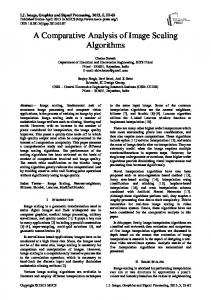
II. SIMULATION ARCHITECTURE A parachute is a device that is used to slow the motion of an object. Parachutes have been a fascination among humans since the ancient times. Earliest evidence of parachutes comes from the documents that are found in the renaissance era, most famously from the documents of Leonardo da Vinci (c.1495) [5]. Computational models for different aspects of parachute jumping have been proposed. Many of the computational models made for parachutes are done for the parachute type known as ribbon-ring parachutes. A Computational Method for Parachute Fluid–Structure Interactions of ribbon-ring parachute has been suggested by K.Takizawa and T.E.Tezdunyar [6]. But in the modern days many parachute jumpers use the parachute type known as ram-air parachutes or parafoils due to their maneuverability. The credit for introducing this model goes to Domina Jalbert. He patented his parafoil parachute design in 1966 as "Multicell wing type aerial device” [7]. The physics behind these two models are different due their shape. The traditional parachute models such as ribbon-ring parachutes slow the motion through the atmosphere by causing a drag. The ram-air parachutes do this by using aerodynamic forces of lift and drag. This enables a better control of speed and direction in these types of parachutes [8]. There are some computational models that are available for these ram-air parachutes which use non-real time calculations, due to their complexity and the amount of computation that has to be done. Most of the calculations done in these models require parallel computing and can't be adapted in to a real time model. One example for such a model is a parallel 3D computational method for fluid-structure interactions in parachute systems, suggested by Vinay Kalro and T.E.Tezduyar [9]. Fig. 1 showcases the architecture of the final system. The Six degree-of-freedom dynamic model is built from the physics equations taken from the literature which are then re-adjusted accordingly to calculate necessary values. The system is initiated using the environmental data as well as physical and mechanical data. The six degree-offreedom model is then solved using a classic fourth-order Runge-Kutta (RK4) solver and the position and Copyright © 2017 MECS
Fig.1. System architecture for a real-time parachute dynamic simulation.
A. Environmental Properties The most important environmental property that we have considered in this research is the wind. Which is an attribute that is at this stage is given as a static value which is represented using the earth fixed coordinate system. This value is fed to the 6DOF freedom model which is then considered in calculations. B. Physical and Mechanical Properties Data related to the parachute is gathered from NASA and University of Notre Dame wind tunnel tests [10] and also from Lingard [11]. These wind tunnel test data is available in a very sparse amount. These data is used in order to initiate each model. Also the data that is gathered from the data-sheets of standard parafoil designs of United States Air Force is used when initiating the parachute dimensions. These are stored in a database with the mechanical properties that are related to the parachute. These physical and mechanical properties of the parachute are fed in to the parachute dynamic model. C. Dynamic Air Density Model The air density changes with the altitude and the density is low in higher altitudes. We have used a dynamic air density model in our solution. Getting the exact values for air density involves lot of dynamic factors such as temperature, pressure of dry air and pressure of water vapor in air. Instead of using all these parameters we have used a model that follows the pattern of the density change with altitude [12]. The following equation is generated as an approximation to the actual pattern of the air density change with altitude in standard units. ρ = −17500h+1.2
I.J. Information Technology and Computer Science, 2017, 3, 19-27
A Real-Time 6DOF Computational Model to Simulate Ram-Air Parachute Dynamics
21
ρ = Air Density h = Altitude of the Parachute
III. 6 DEGREES OF FREEDOM MODEL In this research we are focused on proposing a 6DOF model to simulate the dynamic model of the ram-air parachute. We have used six degrees of freedom model to calculate the position and orientation of the parachute relative to an inertial frame. Three degrees of freedom is used to represent the position of the parachute and another three is used to represent the orientation. The position is presented using coordinates in the inertial reference frame (x, y and z) and the orientation is represented using Euler angles which are pitch, roll and yaw (θ, φ and ψ). While building this model an assumption had to be made that the parachute and the payload is a single rigid body. Throughout the study the aerospace conventions have been used to build the 6DOF model. A. Transformation Matrix The velocities of the parachute system are expressed in the body reference frame and the parameter such as gravitational force is defined in the inertial frame. When we are using these parameters in equations of motion we have to convert the coordinate systems accordingly. Hence we need a transformation matrix to switch from one coordinate system to another. To do so we can define the each Euler rotation using the following transformation matrices where each transformation matrix represents roll, pitch and yaw respectively [13].
B. Forces and Moments Equations According to Newton the force equation can be written as, F maG F m
dV G dt
(1)
(2)
In the above equation the velocity and the forces are defined in the earth fixed frame. But we are considering velocities in the body fixed frame. Hence we have to convert the equation to the body fixed frame. The acceleration can be transformed from the earth fixed frame to the body fixed frame using the following equation. aG
dV G dV B V dt dt
(3)
By using the above equation we can re-write the force equation as following [5]. F m
dV B m V dt
(4)
There are two important external forces that act upon a parachute when it is gliding. One is aerodynamic force and the other force is caused by the gravity. Gravitational force is acted upon the earth fixed inertial frame. But we need to calculate the forces that act upon the body fixed frame. Hence the body fixed gravitational force that acts upon the parafoil can be derived using the transformation matrix as follows. (5) According to the Euler’s theorem any rigid body rotation can be expressed by a single rotation about fixed axis. According to this theorem any orientation can be achieved by the composition of the three elemental rotations. By using this we can create a transformation matrix between the earth-fixed reference frame and the body-fixed reference frame. To do so we have to first rotate the yaw angle over the z axis, then the pitch angle about the y axis and finally the roll angle about the x axis. Finally, we got the following transformation matrix [13]. The standard convention of shortening trigonometric symbols is used in the equation.
The completed force equation for the body fixed system of the parachute can be written as follows.
(6) We can rearrange the formula as following, (7) Also we have to consider about the moments that acts upon the parachute in each axis. The moment in the body-
Copyright © 2017 MECS
I.J. Information Technology and Computer Science, 2017, 3, 19-27
22
A Real-Time 6DOF Computational Model to Simulate Ram-Air Parachute Dynamics
fixed frame of the parachute can be written using the following formula where H is the angular momentum.
(8) The angular momentum of a rigid body can be calculated using: (9) Here ω is the angular velocity vector of the parachute about the center of mass and I, is the moment of inertia. Moment of inertia can be defined using the following matrix [15].
ρ = Air density. V = Velocity of the System S = Area of the parafoil The drag and lift coefficients are dimensionless values which are determined by the type of aero-foil and it is changed with the angle of attack of the wing, or in this case the parachute. Also these coefficients change as the brakes are applied and as a deflection in a trailing edge occurs. What happens as these brakes are applied is also a change in the angle of attack. There are separate researches done in this area to study the behavior of these coefficient values. Practically these values are calculated through wind-tunnel tests. In this research we try to use the wind tunnel test data as well as the coefficient behavior equations found in other researches for calculations. To calculate the aerodynamic force at each axis we have can use the following formula. Here α is the angle of attack and µ is the rigging angle [11].
If we rewrite the angular momentum formula for each axis it can be written as,
(15)
(10) As in the scenario with the forces equation we have to re-write the moment equations to fit the body fixed frame as our parameters are defined in body fixed frame [14]. (11) We can rearrange the formula as following, Fig.2. Angles of a parachute system [2].
(12) C. Calculating Forces and Moments There are basically two types of aerodynamic forces. One is the lift and the other one is the drag force both which are occurred by the movement of the parafoil through a fluid. The formula to calculate the lift force:
As we calculated the aerodynamic forces, aerodynamic moments should also calculate. We have to calculate the aerodynamic moments for the roll, pitch and yaw. They can be shown using the following equation. (16) The moment Ma can be represented through a matrix as following.
(13) The formula to calculate the drag force: (14) L = Total lift force of the parachute system. D = Total drag force of the parachute system. CL = Lift Coefficient CD = Drag Coefficient Copyright © 2017 MECS
Each element in the matrix where each represents aero dynamic moment for roll, pitch and yaw respectively. The characteristic length matrix can be represented using the following matrix where the span of the parachute is b and the reference chord length is c.
I.J. Information Technology and Computer Science, 2017, 3, 19-27
A Real-Time 6DOF Computational Model to Simulate Ram-Air Parachute Dynamics
23
If we write the earth fixed velocities as following,
Each element in the aerodynamic moment coefficient matrix represents the dimensionless moment coefficients for pitch, roll and yaw moments respectively. The aerodynamic forces and the moments are taken around the aerodynamic center of the parachute. But the values in the body fixed frame are considered from the center of the gravity of the parachute. Hence we have to take in to consideration the distance between these two centers and adjust the moment accordingly. If we assume the distance from the center of gravity to aerodynamic center is Zag. This gives the following aerodynamic moment equation.
By using integration we can calculate the distance that the parachute has traveled in each direction as following [5]. (19) The integration gives the final position of the system. But what we are seeking for is a differential equation to calculate the distance value. If we assume that the matrix G represents the positions in the coordination system as [xyz]T. If so we can re-write the above equation as following. (20)
(17) As the aerodynamic moments were taken about the aero-dynamic center and the inertia matrix we discussed in the earlier section was taken about the center of mass, we need to adjust the equation. Here to adjust this we use the parallel axis theorem. In parallel axis theorem it states that the moment of inertia of any object about an axis through its center of mass is the minimum moment of inertia for an axis in that direction in space. The moment of inertia about any axis parallel to that axis through the center of mass is given by Iparaxis = Icm +md2. When we adjust the inertia matrix accordingly we get the following:
D. Translational Kinematics
When we write the earth fixed velocities using body fixed velocities by using the transformational matrix we can re-write the equation as, (21) E. Rotational Kinematics Rotational kinematics is about the rotation of the parachute. If we take the Euler angle rates which are defined in the inertial frame system using matrix as E= [˙φ, ˙θ, ˙ψ]T. In the body fixed reference system the angular velocities are described using ω. The relation between these two can be shown using the following equation [14].
(22)
Translational kinematics concerns only about the velocity of the system relational to the ground. This velocity is called as the kinematic velocity and it can be described using the following matrix. This velocity is referred according to the earth fixed inertial system.
But what we are interested is the inertial system angular velocities. By inverting the above relationship we can get that equation.
(23)
In the body fixed system the velocities are defined using u, v and w. We can use the inverse of the transformation matrix to get the kinematic velocities of the earth fixed inertial frame system.
If we define the transformation matrix above as RkT, then we can re-write the equation as follows. (24)
(18) An important thing that should be noticed is that this Copyright © 2017 MECS
I.J. Information Technology and Computer Science, 2017, 3, 19-27
24
A Real-Time 6DOF Computational Model to Simulate Ram-Air Parachute Dynamics
parameterization has singularities at pitch values of θ = π/2+n∗π radians. In the case of a vertical maneuver which rarely occurs when gliding a ram-air parachute; the above matrix would go to a singularity causing the simulation to stop.
moment of inertia matrices. These matrices can be represented as following.
F. Effects of Apparent Mass When a large body moves through a fluid it generates some motion in a certain amount of fluid mass. Apparent mass is significant for flying objects when the mass of the air is greater than the mass of the object that is moving. The parameter that has to be considered here is the wing loading factor. If wing loading is less than 50 N/m2 then the apparent mass effects should be considered [15]. In this research we try to simulate the parachute model known as RA1 and at a suspended weight of 80kg the parachute has a wing load of 24 N/m2. Hence the need to calculate the apparent mass effect on a ram-air parachute occurs. When calculating the forces that are applied on the parachute it is important to know the pressure distribution of the air. This depends on the relative fluid velocity and the acceleration of the fluid. If the fluid is an ideal fluid, stable motion of the parachute won’t cause any external force. Theoretical results have shown that the force necessary for a solid to accelerate in a fluid like air is greater than the force that is needed to accelerate in the vacuum due to the fact that the fluid resists the acceleration. This change in the motion of the parachute body causes changes in fluid flow and this causes inertial forces to occur due to the changes of the pressure field on the body surfaces. The increase of pressure on the parachute body is proportional to the acceleration of the parafoil. Hence additional forces are also proportional to this acceleration. This can be taken in to account in calculations by increasing the mass of the parachute system. This added mass is known as the apparent mass [16]. The apparent mass changes according to the direction of movement. The same effect occurs when the parachute rotates around its axis. Hence both the apparent mass forces as well as apparent mass moments should be calculated. The accurate values are determined using Computational Fluid Dynamic methods [2] [4]. But in this research we are using the simplified approximate values gained through analytical methods. The following equations can be used to calculate the additional forces and moments generated due to the apparent mass. For the equations of forces and moments we derived earlier these new values should be taken in to consideration. dV M F V dt
(25)
d I F VM F V dt
(26)
Fapp M F
M app I F
With the addition of the apparent mass effects we can rewrite the force equation for the parachute system as following. (27)
(28) As we are interested in the derivative of the velocity to create an ordinary we bring it to one side. There are two terms that has the derivation of velocity and we have to take the common element to separate it. But then the remaining values don’t have the same dimensions. We use an identity matrix to fix this and the equations are rewritten as following.
(29) The moment equation should also be also re-written with the addition of the apparent mass effect. (30)
(31)
Following equations represent the apparent mass and Copyright © 2017 MECS
The apparent mass and inertia terms are defined by Lissaman and Brown [15].
As with the force equation in this equation we are interested in the derivative of the angular velocity
I.J. Information Technology and Computer Science, 2017, 3, 19-27
A Real-Time 6DOF Computational Model to Simulate Ram-Air Parachute Dynamics
25
B. Parameters for Simulation (32)
IV. SIMULATED RESULTS The computational model we have proposed is modeled as a Real-Time Fixed Step Simulation. We have chosen an explicit solver to solve the initial value problem. In our simulation to select a suitable step size for the solver we have used different combinations of step sizes with varying number of iterations. The step size 0.01 gave the best performance in these tests and we are using that value in our model. A. Fourth-Order Runge-Kutta Method In this study we have used the RK4 method as the solver to address the initial value problem and solve the dynamic model. Initial value problem is the problem that arises in modeling of physics attributes where an initial condition has to be given to a set of ordinary differential equations at the given point of domain in the solution. In our scenario the domain is time and we have to give an initial condition at a point of time (generally at t0). The solver is an evolution equation specifying in which way the dynamic model will evolve with time given initial conditions. RK4 method can only be used to solve ordinary differential equations of the form,
We have selected a parachute design which is used by the United States Air Force for the simulation purposes. The model is known as the RA1 and the parachute attributes are shown in the Table 1. The thickness and the distance from the aerodynamic center to gravitational center is an approximation taken from Lingard [xxx]. The proposed model was tested for different test cases in the study. Table 1. RA1 Parachute Attributes Parameter b c t S µ m Zag
Value 9.7 m 3.7 m 0.18*c 35.89 m2 100 120 kg 0.258*c
(33) This means that only first order differential equations can be solved using RK4 and it is not an issue as all the equations we derived are in first order. The RK4 method for our implementation can be written as following. k1 f (tn , yn )
(34)
h h k2 f (tn , yn k1 ) 2 2
(35)
h h k3 f (tn , yn k2 ) 2 2
(36)
k4 f (tn h, yn hk3 )
(37)
Here the h is the step size we are using in the simulation. The calculated value of yn+1 and the tn+1 can be written as,
h yn 1 yn (k1 2k2 2k3 k 4) 6 tn 1 tn h
Copyright © 2017 MECS
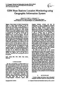
Fig.3. Trajectory of the parachute when no brakes are applied.
(38) (39)
Fig.4. Trajectory of the parachute when half brakes are applied.
We try to analyze the trajectory of the parachute in the 3D space. The trajectory is plotted under three conditions. One test is done without any brakes and the other one is done when half brakes are applied gradually and released. The final test is done when there is an asymmetric trailing edge deflection. When there are no forces applied in the
I.J. Information Technology and Computer Science, 2017, 3, 19-27
26
A Real-Time 6DOF Computational Model to Simulate Ram-Air Parachute Dynamics
direction of Y, values across Y axis doesn't change. Hence the plot is done for X and Z axes for the first two test cases (Fig.3 and Fig.4). The asymmetric brake deflection is kept for the full trajectory time period. The deflection is 0.5 radians. The parachute starts to move in a rotational movement throughout the period (Fig.5).
[5] [6]
[7] [8]
[9]
[10] [11]
[12] Fig.5. Trajectory of the parachute when trailing edges are deflected asymmetrically.
[13]
[14]
V. CONCLUSION In this study we developed a real-time computational model that can be adapted in to a ram-air parachute simulator. The model we proposed behaves according to the principles of aerodynamics. The proposed model can be adapted in to various types of ram-air parachutes that are used for parachute jumping by changing the physical properties of it. One barrier that had to be faced when developing such a model is getting actual data for these properties. Especially parameters such as aerodynamic coefficients were not available to specific models and in reality these can be changed slightly than the values we have calculated using equations. The proposed model can be used to train the basic maneuvers of parachute control such as turning, braking, and flaring which are important to the novice jumpers. But the model doesn’t handle emergency situations such as entanglements of parachute lines and stalling. Hence this model is not provided a hundred percent training though it covers all the basics. REFERENCES [1]
[2]
[3]
[4]
T. E. Tezduyar, S. Sathe, M. Schwaab, J. Pausewang, J. Christopher, and J. Crabtree, “Fluid-structure interaction modeling of ringsail parachutes," Comput. Mech., vol. 43, no. 1, pp. 133-142, 2008. K. Takizawa and T. Tezduyar, "Computational Methods for Parachute Fluid-Structure Interactions," Archives of Computational Methods in Engineering, vol. 19, pp. 125169, 2012. S. Mittal, P. Saxena, and a. Singh, “Computation of twodimensional flows past-air parachutes," Int. J. Numer. Methods Fluids, vol. 35, no. 6, pp. 643-667,2001. T. E. Tezduyar, S. Sathe, J. Pausewang, M. Schwaab, J. Christopher, and J.Crabtree, "Interface projection techniques for fluid-structure interaction modeling with
Copyright © 2017 MECS
[15]
[16]
moving-mesh methods," Comput. Mech., vol. 43, no. 1, pp. 39-49, 2008. E. S. Bruce, "The Parachute," Royal United Services Institution. Journal, vol. 78, pp. 796-801, 1933. K. Takizawa and T. Tezduyar, "Computational Methods for Parachute Fluid-Structure Interactions," Archives of Computational Methods in Engineering, vol. 19, pp. 125169, 2012. D.C. Jalbert, "Multi-cell wing type aerial design", U.S. Patent 3 285 546, Nov.15, 1966. Nh-global.com, “Types Of Parachute." [Online]. Available:http://www.nhglobal.com/parachute/types_man ufacture.html. [Accessed: 05-Jun-2015]. V. Kalro and T. E. Tezduyar, "A parallel 3D computational method for fluid-structure interactions in parachute systems," Computer Methods in Applied Mechanics and Engineering, vol. 190, pp. 321-332, 2000. J. D. Nicolaides and M. A. Tragarz, "ParafoilWind Tunnel Tests," 1971. J. S. Lingard, "Ram-Air Parachute Design," Precis. Aer. Deliv. Semin. 13th AIAA Aerodyn. Decelerator Syst. Technol. Conf., no. May, pp. 1-51, 1995. "Modelling of the Variation of Air Density with Altitude through Pressure, Humidity and Temperature ." [Online]. Available:http://www.emd.dk/files/windpro/WindPRO_A irDensity.pdf. J. Diebel, "Representing attitude: Euler angles, unit quaternions, and rotation vectors," Matrix, vol. 58, pp. 135, 2006. "Flight Dynamics Summary." [Online]. Available: http://aerostudents.com/files/flightDynamics/flightDynam icsFullVersion.pdf. P. Lissaman and G. Brown, "Apparent mass effects on parafoil dynam- ics," in Aerospace Design Conference, American Institute of Aeronau- tics and Astronautics, 1993. G. Kowaleczko, "Apparent masses and inertia moments of the parafoil," J. Theor. Appl. Mech., vol. Vol. 52 nr 3, pp. 605-616, 2014.
Authors’ Profiles Sandaruwan Gunasinghe received his BSc in Computer Science (2016) from the University of Colombo School of Computing, Sri Lanka. Served as the President of Computer Science Society of University of Colombo, UCSC (University of Colombo School of Computing) 2014-2016 Branch Chair of the IEEE Student Branch of University of Colombo School of Computing (2015-2016) He is currently a Software Engineer, at the MillenniumIT, Sri Lanka. His Research Interests are Modelling and Simulation, Real-time Simulation, Physics based Modelling, Distributed Systems.
G.K.A Dias received his BSc in Physical Science (1982) from the University of Colombo, Sri Lanka, Postgraduate Diploma in Computer Studies from University of Essex,UK (1986), and MPhil in Computer Science from University of Wales, UK (1995).
I.J. Information Technology and Computer Science, 2017, 3, 19-27
A Real-Time 6DOF Computational Model to Simulate Ram-Air Parachute Dynamics
27
Served as the Head/Department of Communication and Media Technologies, UCSC (University of Colombo School of Computing) 2010-2015 Coordinator of the Third Country and In-Country Training Programme conducted by UCSC and JICA (Japanese International Cooperation Agency (2005-2010) He is currently a Senior Lecturer Gr. I, at the UCSC, Sri Lanka. His Research Interests are Computer Aided Software Engineering, Multimedia for Education, Modelling and Simulation, Rich internet Web applications, Conceptual Modeling, Model Driven Engineering.
Damitha Sandaruwan received his BSc in Physical Science from the University of Colombo, Sri Lanka, PhD in Computer Science from University of Colombo School of Computing (2015). Media Coordinator of the Advanced Digital Media Technology Centre (ADMTC) UCSC (2008-2014). Co-investigator of the Modelling and Simulation Research Group, UCSC, Sri Lanka. He is currently a Senior Lecturer Gr. II, at the UCSC, Sri Lanka. His Research Interests are Real-time Simulation, Modelling and Simulation, Computer Graphic and Vision.
Maheshya Weerasinghe received her BSc in Computer Science (2014) from the University of Colombo School of Computing, Sri Lanka. Student Member of the Computer Society and IEEE Student Branch of University of Colombo School of Computing (20102014). Member of the Modelling and Simulation Research Group, UCSC, Sri Lanka 2014-Present. She is currently a Research Assistant, at the Modelling and Simulation Research Group, UCSC, Sri Lanka. Her Research Interests are Modelling and Simulation, Cognitive Neuroscience, Game based Learning, Cognitive Rehabilitation, Quantum Computing.
How to cite this paper: Sandaruwan Gunasinghe, GKA Dias, Damitha Sandaruwan, Maheshya Weerasinghe,"A Real-Time 6DOF Computational Model to Simulate Ram-Air Parachute Dynamics", International Journal of Information Technology and Computer Science (IJITCS), Vol.9, No.3, pp.19-27, 2017. DOI: 10.5815/ijitcs.2017.03.03
Copyright © 2017 MECS
I.J. Information Technology and Computer Science, 2017, 3, 19-27