and the diï¬usion of free-distributed software packages has given the possibility .... PC. For this board, a loader and a DSP-monitor. have been developed under ...
Copyright © 2002 IFAC 15th Triennial World Congress, Barcelona, Spain
A REAL-TIME CONTROL SYSTEM FOR INDUSTRIAL ROBOTS AND CONTROL APPLICATIONS BASED ON REAL-TIME LINUX Alessandro Macchelli ∗ Claudio Melchiorri ∗
∗
DEIS, University of Bologna, Via Risorgimento 2, 40136 Bologna, Italy email: {amacchelli, cmelchiorri}@deis.unibo.it
Abstract: Rapid prototyping is a well recognized need in the design and development phases of advanced systems for automation. In particular, this concept is also important for the design and experimentation of control algorithms and new mechanical prototypes in advanced robotics. Moreover, flexibility, short development times and contained economical costs are other important features considered in developing new industrial applications and, of course, new robotic and control system experimental set-ups. Recently, the growth in performances of low-cost PC-based architectures and the diffusion of free-distributed software packages has given the possibility of developing rapid prototyping tools taking into account all these needs. In this work, we present the real-time control system of an industrial manipulator, the Comau SMART 3-S, developed under RTAI-Linux, a real-time variant of Linux. The main goal was to build a flexible and highly configurable robotic setup to quickly test new control algorithms and to easily (and safely) use the robot in different manipulation tasks. Keywords: real-time operating systems, industrial robots, robot programming
1. INTRODUCTION
both with the aim of giving Linux the possibility to implement hard real-time applications.
In a sense, the advent of real-time variants of the popular desktop operating system Linux could be considered a sort of milestone for the development process of real-time applications. As a matter of fact, this kind of systems provide noticeable performances that, together with availability of the source codes, powerful development tools and, generally speaking, detailed documentation, could be the starting point for setting up new standards for advanced development environments. These operating systems are distributed under the GNU Public License, so they are freely available and configurable to meet the desired requirements. According to this model, the RT-Linux (Barbanov, 1997), (RT-Linux web site, 2001), and RTAI-Linux (Bianchi et al., 1999), (RTAI-Linux web site, 2001) projects took place,
In this paper, the real-time control system of an industrial robot (a Comau SMART 3-S) under RTAI-Linux is described, as well as the creation of a flexible experimental set-up for using the robot in different tasks and with different tools (in particular a vision system and an advanced gripper). This project is still under development at the Laboratory of Automation and Robotics (LAR) of the University of Bologna.
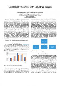
2. THE EXPERIMENTAL SET-UP The main component of the experimental set-up is a Comau SMART 3-S robot. This is a standard industrial 6 degrees of freedom anthropomorphic
USER (keyboard, mouse, joystick)
ROBOT Comau SMART 3−S
C3G−9000 Controller
High−speed link
RTAI−Linux System
DSP
A.S.I. Gripper Gripper Software
TCP/IP link over Internet
Vision System A.S.I. Gripper Sub−system
Frame−grabber
TCP/IP link over Internet (client/server appl.)
Vision Soft.
Vision sub−system
Fig. 1. The experimental set-up: a general overview. manipulator with a non-spherical wrist. Each joint is actuated by a DC-brushless motor, and its angular position is measured by a resolver. The robot is equipped with the standard controller C3G-9000. Basically, this controller is composed of three parts: a user interface, a control unit, and a driver unit. The control unit consists of a Motorola VME bus rack with two boards. The first board (SCC) is equipped with a DSP and carries out all the control tasks (trajectory planning, direct and inverse kinematics, etc.), while the second board (RBC) is responsible for the man-machine interface and for interpreting PLD2 user’s programs. A shared memory area is available on this board: this is a memory area accessible from each board connected to the VME bus. In the experimental set-up available at LAR, the C3G-9000 controller is open, that is the VME bus is connected with an ISA-PC bus via a pair of Bit3 boards, one inside the controller and the other inside a PC, running under RTAI-Linux, that implements the real-time control algorithms. The two boards are connected with a high-speed cable. A data exchange between PC and controller is possible via the shared memory area on the RBC board inside the controller and synchronization can be achieved by an interrupt signal generated by the controller itself. In this configuration, position and velocity loops managed by the C3G9000 are opened, and all the safety protections are disabled. As a matter of fact, the controller is only used as an interface between the resolvers and drives on the robot and the PC. Therefore, in each sampling period the real-time control system running on the PC must acquire the data from the encoders, compute the new control input for the actuators and send their values to the C3G-9000.
On the robot wrist, besides a standard force/torque sensor acquired by the RTAI-Linux PC, a vision system and the A.S.I. Gripper (Biagiotti et al., 2000), (ASI-Gripper web site, 2001) are installed. The vision system is used to provide visual information about the environment and, in particular, about objects within the workspace of the robot. These information are needed when we decide to track a moving object in the workspace with the robot, or to move the robot in a desired position in order to grasp an object with the gripper. At the moment, the vision system is connected to a frame-grabber board installed in another PC, and the information exchange with the robot control system occurs by the Internet via TCP/IP. The vision software runs under a non real-time Linux system, so it will not be discussed in detail in the following sections. The A.S.I. Gripper has three degrees of freedom, and is particularly suited for no-gravity manipulation tasks in space applications, since it can interact with free-floating and irregularly shaped objects. Its control algorithms are executed on a custom DSP board (based on the TMS320C32 chip) that is installed, at the moment, in a third PC. For this board, a loader and a DSP-monitor have been developed under Linux, together with some drivers for the DSP board. By now, we are still developing the information exchange mechanisms between the robot/vision system and the gripper: the idea is to use the visual information and all the data that the sensory equipment on the gripper provides in order to move the robot in ‘optimal’ configuration for grasping objects or tracking moving targets. At the moment, the visual information can be used only to place the gripper in a position of the robot’s workspace so that the object framed by the vision system can
Kernel space
User space
Virtual Teach−Pendant
Control
Mouse Interface
FIFOs Security
RTMon
Vision Subs. Client Communication
Security configuration
Comau SMART 3S
Fig. 2. The real-time module: organization and user-space communication channels. be grasped. Fig. 1 gives a general overview of the set-up.
3. REAL-TIME CONTROL OF THE ROBOT The software developed for the control of the Comau SMART 3-S is divided into two distinct modules: a real-time module (see Sec. 3.1), which executes the control algorithms and communicates directly with the plant (robot), and a non real-time application (see Sec. 3.2) that provides a user interface for the real-time module. Clearly, some communication mechanisms exist to provide an information exchange between the two parts. Moreover, the real-time module is periodically activated by an external interrupt signal generated by the C3G-9000 controller. The adopted real-time Linux variant is RTAI, already successfully used in other robotic applications developed in the past at LAR, (Arduini et al., 2001; Macchelli et al., 2000). A noticeable experimental activity has been carried out in this context, also comparing the performances of control system based on RTAI-Linux with other commercially available OS, such as QNX, (Melucci, 2000).
3.1 The real-time module The starting point in the development of the realtime control module for the SMART 3-S robot was to create a modular and flexible structure in order to have the possibility of a quick testing of new control algorithms and fast implementation of new robot applications. The code is divided into three main sub-modules, providing: • communication with robot SMART 3-S; • security tests;
• implementation of the robot control algorithms. The communication module is used for reading and writing data on the shared memory area in the C3G-9000 controller. In particular, this module reads the six joint positions and writes six current set-points for the DC drives. Moreover, it implements the drive on/off function. This is the only module that gets access to the shared area on the RBC board in the controller. In presence of an externally generated interrupt (in this case, the synchronization interrupt is originated by the robot controller), RTAI does not automatically save the FPU contest before a task switching, so it is this module that have to provide this function. The security module implements software range delimiters (saturation). Two kinds of range delimiters have been implemented: absolute and relative. The relative saturation is really useful when we want to check the stability around a certain configuration of a control algorithm without any risk. Moreover, the security module limits the joint speeds, checks if some of the joints is blocked or if the current set points are too high. In particular, the last two tests are needed to prevent drives damages. If the first three tests are not passed, then the robot is stopped; as regard the last one, we only execute a software saturation to the maximum allowed current value. The control module implements the control algorithms and, in particular it is responsible for trajectory planning, both in joint and Cartesian space, and for robot regulation. The sub-module that implements the regulation algorithms may change according to the control scheme under development. e.g. decentralized control, multivariable centralized control, and so on. As far as the trajectory planning in concerned, since in most of the application (e.g. with the
(a) Virtual Teach-Pendant.
(b) Mouse-Interface.
Fig. 3. Two screen-shots of user interface applications. vision system) the desired trajectory is not known before the execution of a task, we have implemented a trajectory generator using a nonlinear filter with constraints on maximum speed and acceleration (Melchiorri, 2000; Zanasi and Morselli, 2001). All these real-time functions are compiled in a kernel module and dynamically linked to the realtime kernel of the operating system. Since the user needs to interact with the robot, some communication channels between kernel space and user space are needed. Each module can exchange data with the user space applications by its own channels. Since in all the situations the amount of data that we send from/to the kernel module is not relevant, we decided to implement all the communication channels using FIFOs. This solution provides robustness and a built-in coordination/synchronization mechanism between sender and receiver. From the user space it is possible to send the drive on/off command to the communication module of the real time process, and it is possible to change in run-time some parameters in the security module (this is a function that must be disabled when testing new control schemes). Concerning the control module, it can receive commands from user space applications and send back to them information about internal variables of the robot (e.g. joint positions and drive currents). In this manner, it is possible to move the robot with a keyboard, a mouse or a joystick , to interface it with other applications for state-tracing or for movements under vision system control.
Fig. 2 gives a general overview of the real-time module and of the communication channels with user space applications.
3.2 The user-space applications The user-space software can be divided into two main categories: i) user-to-robot and applicationto-robot interface applications, ii) robot-statemonitoring applications. With user-to-robot we intend any application that will help the user to move the robot. The Virtual Teach-Pendant and the Mouse-Interface belong to this category: with them the user can easily move the robot in joint and Cartesian space. In the last case the reference frame can be chosen either on the base of the robot or on the end-effector. Moreover, an interface with a joystick is provided. In Fig. 3 two screen-shots of the user interface applications are shown. With application-to-robot interface we intend an application that provides a basic interface for a stand alone software that needs to communicate with the real-time module and, clearly, with the robot itself. For example, by means of this interface the vision system can send commands to the Comau SMART 3-S in order to follow a user-selected object in the workspace. Since the TCP/IP protocol is used to connect robot and vision system, a simple client/server application has been developed: the client application runs on the RTAI-Linux system and the server on the Linux PC that manages the vision tasks. In control applications, it is important to be able to check the state of the plant and the behav-
(a) RTMon: the main window.
(b) RTMon: the main configuration window.
Fig. 4. RTMon: two screen-shots. ior of the controller: every application needs a proper monitoring software that should be easily configurable and with a user-friendly interface. Following these criteria, we have equipped our system with a specific monitoring application: the RTMon. Using the FIFO channels between user and kernel space, RTMon can display and continuously plot the state of the internal variables of the robot (angular joint position, working space position, set-points, drive currents, etc.) and save the desired data in Matlab compliant format. In fig. 4 two screen-shots of the RTMon application are reported.
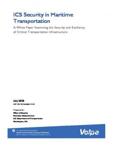
4. COMAU SMART 3-S WITH CAMERA AND GRIPPER As already mentioned in Sec. 1, the vision algorithms are implemented under another Linuxbased system, connected via Internet with the real-time system that directly controls the robot. The communication protocol between the two systems consists in a set of commands that the vision system sends to the robot, in order to execute specific tasks/movements. In Fig. 5, the Comau SMART 3-S with both the camera system and the A.S.I. Gripper mounted on wrist is shown. A typical task for of this system is to take an object selected by the user within the robot’s work-space by using the gripper mounted on its wrist. The procedure can be divided into five main steps. (1) The user moves the robot using the keyboard, mouse or joystick until the vision system frames the object to be grasped;
(2) The vision system automatically moves the robot in order to align the end-effector (i.e. the gripper) with the object. The vision algorithms can deal even with slowly moving objects: it is the network delay that mainly reduces the tracking performances. (3) Since an estimation of the actual distance between object and end-effector is needed and the vision system is not stereo, the robot is moved along the camera-object direction in order to take two pictures of the object and then calculate the unknown distance. (4) Using the distance information, the robot is moved in order to reach a given distance from the object. (5) Finally, the right position for the grasp of the object is achieved; at the moment this step is executed simply moving the robot of a fixed distance: we are working on the use of the informations provided by the proximity sensors of the gripper (Biagiotti et al., 2000) in order to obtain a better positioning of the gripper itself. The robot’s movements in step 2 and 4 are managed by the vision system sending roll-pitch-yaw and normal-slide-approach commands to the manipulator in order to reach the object aligned with the camera. As regard steps 3 and 5, at the moment these movements are pre-calculated. These operations are executed safely and further modifications of the control systems, as well as the development of new tasks, can be easily accomplished with this control architecture.
(a)
(b)
Fig. 5. The robot Comau SMART 3-S with the camera system and the A.S.I. Gripper both mounted on wrist. 5. CONCLUSIONS AND FUTURE WORK In the present work, we have briefly described the main components of our robotic and control system research experimental set-up, i.e. the industrial manipulator Comau SMART 3-S, its realtime control system, the vision subsystem and how we have assembled these two sub-systems for real-time operations using standard network facilities provided by the Linux operating system. Our future work will be aimed at improving performances of the current system in particular with a better integration between robot-vision system and the A.S.I. Gripper. Other activities will be devoted to further study the real-time performances of RT-Linux, to compare it to commercial products, and to develop applications for high-dynamic motion-control systems. Acknowledgments. This work has been supported by MISTRAL, a PRIN’00 project funded by MIUR. The authors wish to thank D. Pescoller for the implementation of the Comau SMART 3-S control software and J. Aguilera for the implementation of the vision algorithms. 6. REFERENCES Arduini, D., P. Arcara and C. Melchiorri (2001). An experimental set-up for robotics and control systems research using real-time linux and comau smart 3-s robot. Milan, Italy. Barbanov, M. (1997). A Linux-based Real-Time Operative System. New Mexico Institute of Mining and Technology. Socorro, USA. Biagiotti, L., C. Melchiorri and G. Vassura (2000). Control of a robotic gripper for grasping
objects in no-gravity conditions. ICRA’01, IEEE Int. Conf. on Robotics and Automation, Seoul, Corea. Bianchi, E., L. Dozio, P. Mantegazza and D. Martini (1999). Applications of a new variant of rt-linux in digital control of dynamic systems. Dipartimento di Ingegneria Aerospaziale, Politecnico di Milano. Macchelli, A., C. Melchiorri and D. Arduini (2000). Real-time linux control of a haptic interface for visually impaired persons. IFAC Symposium on Robot Control – SYROCO’00, Vienna, Austria. ASI-Gripper web site (2001). http://www-lar.deis.unibo.it/activities/asi/. RT-Linux web site (2001). http://www.rtlinux.org/. RTAI-Linux web site (2001). http://www.rtai.org/. Melchiorri, C. (2000). Traiettorie per azionamenti elettrici. Esculapio Ed.. Bologna, Italy. Melucci, P. (2000). Confronto di applicazioni di controllo in tempo reale sviluppate in RTAILinux e QNX. Laurea Thesis (in italian), DEIS. Univ. of Bologna, Italy. Zanasi, R. and R. Morselli (2001). Second order smooth trajectory generator with nonlinear constraints. European Control Conference – ECC’01, Oporto, Portugal.