A Real-time Driver Visual Attention Monitoring System Jorge P. Batista ISR-Institute of Systems and Robotics, DEEC/FCT University of Coimbra, Coimbra - PORTUGAL
[email protected]
Abstract. This paper describes a framework for analyzing video sequences of a driver and determining his level of attention. The proposed system deals with the computation of eyelid movement parameters and head (face) orientation estimation. The system relies on pupil detection to robustly track the driver’s head pose and monitoring its level of fatigue. Visual information is acquired using a specially designed solution combining a CCD video camera with an NIR illumination system. The system is fully automatic and classifies rotation in all-view direction, detects eye blinking and eye closure and recovers the gaze of the eyes. Experimental results using real images demonstrates the accuracy and robustness of the proposed solution.
1
Introduction
The ever-increasing number of traffic accidents in the EC due to the diminished driver’s vigilance level has became a serious problem to society. Driver fatigue resulting from sleep deprivation or sleep disorders is an important factor in the increasing number of accidents on today’s roads. Statistics shows that a leading cause for fatal or injurycausing traffic accidents is due to drivers with a diminished vigilance level. Automatically detecting the visual attention level of drivers early enough to warm them about their lack of adequate visual attention due to fatigue may save a significant amount of lives and personal suffering. Therefore, it is important to explore the use of innovative technologies for solving the driver visual attention monitoring problem. Many efforts have been reported in the literature on developing non-intrusive realtime image-based fatigue monitoring systems [2, 7–9, 11]. Measuring fatigue in the workplace is a complex process. There are four kinds of measures that are typically used in measuring fatigue: physiological, behavioral, subjective self-report and performance measures [15]. An important physiological measure that has been studied to detect fatigue has been eye-movements. Several eye-movements were used to measure fatigue like blink rate, blink duration, long closure rate, blink amplitude, saccade rate and peak saccade velocity. An increasing popular method of detecting the presence of fatigue is the use of a measure called PERCLOS [15]. This measure attempts to detect the percentage of eye-lid closure as a measure of real time fatigue.The present solution focuses on rotation of the head and eye blinking, two important cues for determining driver visual attention, to gather statistics about the driver’s visual attention level. The organization of the paper is as follows. In section 2, the image acquisition system and illuminator is presented. The pupil detection solution based on the Purkinje images is presented on section 3. This entails pupil detection, tracking and eye gaze
2 estimation. In section 4, the automated driver visual attention statistics and some results are given and in section 5 the details of the 3D head orientation and results are presented. Finally, conclusions are presented in section 6.
2
Image acquisition system and illuminator
To take advantage of the Purkinje images, a special camera-illuminator device was constructed. For that purpose, several NIR light emitting diodes (the TSHA650 from Vishay Telefunken) were distributed evenly and symmetrically along the circumference of two coplanar concentric rings [8] (see fig. 1). The center of the rings coincides with the camera optical axis. The IR light source illuminates the driver’s eye and generates two kinds of pupil images: bright and dark pupil images. The bright pupil image is produced when the inner ring of IR leds is on and the dark pupil image when the outer ring is on. In order to take dark and bright pupil images simultaneously, the inner and outer ring control make use of the even/odd video signal information. The first Purkinje image, the so-called glint, is observed in both pupil images. A narrow band NIR filter (700-900 nm) was placed in front of the optical system of the camera to minimize interference from light sources beyond IR light and to maintain uniform illumination under different light conditions.
3
Pupil detection, tracking and gaze estimation
A robust and accurate pupil detection is crucial for the subsequent eyelid movements monitoring, eye gaze determination and face orientation estimation. Pupil detection is obtained by IR illumination after removing external illumination disturbance, and the result will be used on pupil tracking via Kalman filtering.
3.1
Pupil and glint detection
At the NIR wavelength, pupils reflect almost all the IR light they receive along the path back to the camera, producing the bright pupil effect. If illuminated off the camera optical axis, the pupils appear dark since the reflected light will not enter the camera lens. This produces the so-called dark pupil effects. Pupil detection involves locating pupils in the image. The narrow band NIR filter that was attached to the camera lens almost remove the ambient light interference. To robustly detect the pupils, each frame is separated into two image fields, representing the bright and dark pupil images separately (fig. 2). The image subtraction of these two image fields will produce an image with an high intensity contrast between the
Fig. 1. Image Acquisition and NIR Illuminator .
3
Fig. 2. The bright and dark pupil effect.
pupils and the rest of the image, allowing easy pupil segmentation via a simple global thresholding. This yields a binary image consisting of binary blobs that may represent the pupils. The pupils are detected by searching the entire image to locate two blobs that satisfy certain size, shape and distance constraints. The relationship between the shape and size of the pupils and the distance between each other is defined based on the anthropometric measures of the human face. After the correct detection of both pupils, an ellipse fitting is applied to each pupil and the centroid of the resulting ellipse is returned as the position of the detected pupil. To take advantage of the high contrast between the glint and the rest of the image, the glint is detected using the dark image field. The bimodal intensity distribution of the dark image field allows a robust detection of the glint via simple image thresholding in the neighborhood region of the pupils. Once again, the shape and position distribution of the glints are used to constrain the segmentation results. Since the glints are visible in both image fields, the glints detected in the dark image field are cross-checked with the results obtained with the bright image field. The centroid of the segmented blob of a glint is returned as the image position of the glint.
3.2
Pupil tracking
To continuously monitor the driver visual attention, it is important to track the eyes in real-time. We implemented a Kalman filter tracker to accomplish this task. This tracker is aimed to fulfill two purposes: estimate the position and uncertainty of moving targets in the next frame and to filter out noise input data. The target state vector is X = [pl pr gl gr p˙l p˙r g˙l g˙r ]T where pi = (xi , yi )|i=pr ,pl and p˙i = (x˙i , y˙i )|i=pr ,pl are the image position and image velocity of the pupils and gi = (xi , yi )|i=gr ,gl and g˙i = (x˙i , y˙i )|i=gr ,gl are the image position and image velocity of the glints. The system model used is the following discrete model: Xk = f (Xk−1 , k − 1) + Wk
Zk = h (Xk , k) + Vk
(1)
where Wk is a discrete-time white noise process with mean zero and covariance matrix Q, Vk is a discrete-time white noise process with mean zero and covariance matrix R, and Wj , Vk , and X0 are uncorrelated for all j and k. We considered the assumption that trajectories are locally linear in 2D, resulting for the system model the following linear difference equation Xk = A · Xk−1 + Wk where the system evolution matrix, Ak , is based on first order Newtonian dynamics and assumed time invariant. The measurement vector is Zk = [pl pr gl gr ]T and is related to the state vector via the measurement equation Zk = C · Xk + Vk .
4
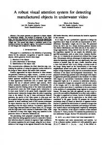
Fig. 3. PERCLOS (left) and AECS (right) measurements over a period of 80 seconds.
The state covariance matrix Pk encodes the information of the ellipse of uncertainty of the estimation and can be used to compute the search area for the pupils and the glints. Specifically, the search area size was chosen as [H, W ] = [20 + 0.2 · Pk (y, y), 25 + 0.3 · Pk (x, x)].
3.3
Head-Eye gaze estimation
As stated before, the first and the fourth images of Purkinje (dual-images of Purkinje) supply a very reliable information for head-eye gaze estimation [3, 10]. When the headeye is panned horizontally or vertically, the relative positioning of the glint and the centre of the bright-eye change accordingly, and the direction of gaze can be calculated from these relative positions. For a roll free head rotation, the locations of the pupils will share a common image line. In case of a pure roll head rotation (frontal orientation), the orientation of the line defined by both pupils gives an estimation of the roll angle of the head and the relative positioning of the glint and the pupil is the same in each one of the eyes. In the case of a head-eye yaw rotation, this relative positioning is different for each one of the eyes, being equal for the case of a pitch head-eye rotation. This observation is used to obtain a rough estimation of the direction of gaze. Assuming roll free head rotation, the dual-images of Purkinje supply the following measures Dyaw = (|xpr − xgr |) − (|xpl − xgl |)
Dpitch = 0.5 ∗ ((ypr − ygr ) + (ypl − ygl )) (2)
that are used to estimate the head-eye gaze orientation. Dyaw is null for a frontal head pose and shows positive/negative values for right/left head rotations. The eye gaze orientation is measured on the eye with less pupil-glint relative position. Using these measures, the head-eye gaze orientation is obtained via a linear mapping procedure. To make these measures scale invariant, they are normalized by dividing over the interpupil distance value of the front view. An off-line calibration procedure was carried on, quantizing the head gaze orientation in steps of 5o .
4
Automated driver visual attention statistics
Of the drowsiness-detection measures, the measure referred to as PERCLOS was found to be the most reliable and valid determination of a drivers alertness level. PERCLOS is
5 the percentage of eyelid closure of the pupil over time and reflects slow eyelid closures (droops) rather than blinks. To measure eyelid closure of the pupil, the size of the pupil was taken as the average size of both pupils and the rate of closure is defined as rateclosure = 1 − (pupilsize)/max(pupilsize), defining a closed eye if rateclosure ≥ 0.8. AECS is the average eye closure speed [9], which means the amount of time needed to fully close the eyes and to fully open the eyes. An individual eye closure speed is defined as the time period during which the 0.2 ≤ rateclossure ≤ 0.8. Figure 3 show the PERCLOS and AECS for a period of 80 seconds.
5
Driver head orientation
The presented approach models the shape of the driver’s face with an ellipse, since human faces can be accurately modelled with an ellipse and is less sensitive to facial expression changes. To recover the 3D face pose from a single image, it is assumed that the ratio of the major and minor axes of the 3D face ellipse is know. This ratio is obtained through the anthropometric face statistics. Our purpose is to recover the three angles of rotation: yaw (around vertical axis), pitch (around horizontal axis) and roll (around the optical axis).
5.1
Image face ellipse detection and tracking
The image face ellipse detection and tracking is based on three major steps: i) obtain an approximate location of the face based on the positions of the eyes. Since the pupil position varies as a function of the eye gaze movements, the approximate location of the face is based on the location of the glints which are invariants to the eye gaze. ii) determine the best fitted ellipse for the image face by maximizing the normalized sum of the gradients around the edges of the face. iii) Ellipse face tracking using a Kalman filter. In order to correctly detect the face ellipse, some constraints must be considered, in special size, location and orientation. The distance between the detected glints and their location are used to constrain the size and location of the image face ellipse. The orientation of the line that passes through both glints is directly related to the 3D face roll rotation. For roll free face poses this line remains horizontal, which means that it is invariant to the yaw and pitch rotations. Under this constraints, the roll angle (ψ) is defined by ψ = atan[(ypl − ypr )/(xpl − xpr )]. Under frontal orientation, a weak perspective projection can be assumed and the face symmetry for the location of the eyes within the 3D face ellipse hold for the image face ellipse. This means that the major axis of the face ellipse is normal to the line connecting the two glints and pass through the center of the line. In fact, these constraints doesn’t hold for non-frontal orientation and the orientation of the major line is not normal to the connecting line. Although, the solution adopted kept the constrain that the major axis of the ellipse pass through the center of the line, considering the existence of an angle α between the major axis and the normal to the line that connect the two glints. Assuming the existence of an ellipse coordinate frame located at the middle point of the glints connecting line, with the X and Y axis aligned with the minor and major axes of the ellipse, respectively, the image face ellipse is characterized by four parameters (mi , ni , d, α), where mi and ni are the lengths of the major and minor semi-axis of the ellipse, respectively, d is the distance to the image ellipse center and α is the rotation angle.
6
Fig. 4. Image face ellipse detection.
Taking the approach proposed by Birchfield [4], the image face ellipse can be detected as the one that minimizes the normalized sum of the gradient magnitude projected along the directions orthogonal PNto the ellipse 2around the perimeter of the ellipse. This can be formulated has ε = N1 |n(i) · g(i)| where n(i) is the unit vector nori=1 mal to the ellipse at pixel i, g(i) is the pixel intensity gradient and (·) denotes dot product. The best face ellipse is χ = arg maxe∈E (ε2 ) where the search space E is the set of possible ellipses produced by varying the four parameters of the ellipse. In order to constraint the searching space, the rough estimation of the 3D face orientation obtained via the dual-images of Purkinje is used to define an initial estimate for these parameters. The four ellipse parameters are tracked via a kalman filter. Figure 4 show the result of the image face ellipse detection.
5.2
Face orientation
Consider an object coordinate frame attached to the 3D face ellipse, with its origin located on the center of the ellipse and its X and Y axes aligned with the major and minor axes of the ellipse. The Z axis is located normal to the 3D ellipse plane. The camera coordinate frame is located at the camera optical center with the Xc and Yc aligned with the image directions with the Zc along the optical axis. Since the 3D face ellipse is located on the plane Z = 0, the projection equation that characterizes the relationship between an image face ellipse point pi = (x, y, 1)T and the corresponding 3D face ellipse point Pi = (X, Y, 1)T is given by pi = βK[R|t]Pi where K represents the camera intrinsic parameters matrix, M = [R|t] = [r1 r2 |t] is the extrinsic parameters matrix and β = λ/f is an unknown scalar. Representing x £ ¤ a c/2 d/2 (3) x y 1 c/2 b e/2 y = 0 d/2 e/2 f 1 the matricial generic formula of an ellipse, the 3D face ellipse and the image face ellipse can be defined, respectively, as
£
¤
£
XY 1 Q XY 1
¤T
=0
£
¤
£
xy1 A xy1
¤T
= 0.
(4)
Substituting pi = βKM Pi to Eq. 4 lead to
£
¤
£
X Y 1 βM T K T AKM X Y 1
¤T
= 0.
(5)
Denoting B = K T AK, the 3D ellipse matrix Q yields Q = βM T BM . Let the length of the major and minor axis of the 3D face ellipse be m and n, respectively, and since the object frame is located on the center of the ellipse, the
7
Fig. 5. Head face orientation estimation.
ellipse matrix Q is parameterized as
1/m2 0 0 Q= 0 1/n2 0 0 0 −1
(6)
resulting the equation
r1T Br1 r1T Br2 r1T Bt 1/m2 0 0 0 1/n2 0 = β r2T Br1 r2T Br2 r2T Bt tT Br1 tT Br2 tT Bt 0 0 −1
(7)
Due to the symmetry of the matrix, there are only six equations (constraints) for a total of nine unknowns. Since the roll angle was already obtained, the face orientation can be defined just by the yaw and pitch rotation. Assuming a null translation vector, the rotation matrix obtained from the yaw and pitch rotation is
£
R = Rσ Rυ = r 1 r 2 r 3
¤
cos(σ) sin(σ)sin(υ) −sin(σ)cos(υ) . = 0 cos(υ) sin(υ) sin(σ) −cos(σ)sin(υ) cos(σ)cos(υ)
(8)
Assuming that the ratio between the major and minor axis if the 3D face ellipse is know by anthropometric face analysis, and letting c = m2 /n2 represent this ratio, the 2 × 2 sub-matrix yields
·
rT Br1 r1T Br2 β 1T r2 Br1 r2T Br2
¸
· =
1/m2 0 0 1/n2
¸ (9)
resulting the following constraint equations r1T Br2 = 0
(10)
βr1T Br1 βr2T Br2 n2 T T = ⇔ r Br = r2 Br2 ⇔ r2T Br2 − cr1T Br1 = 0. 1 1 1/m2 1/22 m2
(11)
Using these two equations it is possible to solve for the pitch and yaw iteratively. The initial estimates of 0o for both angles has been used with correct convergence results. This approach was tested with several real images with good results. Although, the accuracy obtained with this approach is highly dependent on the image face ellipse obtained. Figure 5 show the results obtained with the face orientation estimation approach.
8
6
Conclusions
A Real-time Driver Visual Attention Monitoring System was presented. A special hardware image acquisition and illuminator system was described to take advantage of the dual-images of Purkinje. A efficient and simple solution for pupil detection was presented that were used to take some drossiness measure in real-time. A rough estimation of the head-eye gaze was described based on the dual-images of Purkinje and finally an ellipse based face orientation estimation was presented. Although the good results obtained with the face orientation estimation, it reveals to be highly dependent on the image face ellipse detection. Further research is necessary in order to improve the accuracy of the image face ellipse detection.
References 1. H.D. Crane, The Purkinje Image Eyetracker, Image Stabilization, and Related Forms of Stimulus Manipulation, In Visual Science and Engineering: Models and Applications, D. H. Kelly, Ed. Marcel Dekker, Inc., New York, NY, 1994. 2. A. Yilmaz, et al., Automatic feature fetection and pose recovery for faces. ACCV2002, Melbourne, Australia, 2002. 3. T. N. Cornsweet et al., Accurate two-dimensional eye tracker using first and fourth purkinje images, J. Opt. Soc. Amer., vol. 63, no. 8 August 1973. 4. S. Birchfield, Elliptical head tracking using intensity gradients and color histograms, IEEE CVPR, 1998. 5. A.H. Gee et al., Determining the gaze of faces in images, Image and Vision Computing, 12 (10), 1994. 6. A.T. Horprasert et al., Computing 3D head orientation from a monocular image sequence SPIE, 25th AIPR workshop: Emerging Applications of Computer Vision 2962, 1996. 7. P. Smith et al., Determining Driver Visual Attention with one camera, IEEE Trans. on Intelligent Transportation Systems, vol.4, n.4, Dezember, 2003. 8. Qiang Ji et al., Real-time eye, gaze and face pose tracking for monitoring driver vigilance, Real-Time Imaging, 8, 2002. 9. Qiang Ji et al., 3D pose estimation and tracking from a monocular camera, Image and Vision Computing, 2002. 10. J.G. Wang et al. Study on Eye Gaze Estimation, IEEE Trans. on Systems, Man, and CyberneticsPART B: Cybernetics, vol. 32, no. 3, JUNE 2002. 11. R. Grace, A drowsy driver detection system for heavy vehicles, Conf. on Ocular Measures of Driver Alertness, 1999. 12. C. Morimoto et al., Pupil detection and tracking using multiple light sources, Image and Vision Computing, 18, 2000. 13. S.Y. Ho et al., An analytic solution for the pose determination of human faces from a monocular image, In Pattern Recognition Letters, 19, 1998. 14. M. Mallis et al., Ocular measurement as an index of fatigue and as the basis for alertness management: experiment on performance-based validation of technologies, 1999. 15. P. Sherry et al., Fatigue Countermeasures in the Railroad Industry: Past and Current Developments, Published by Association of American Railroads, 2000.