Journal of Mobile, Embedded and Distributed Systems, vol. III, no. 4, 2011 ISSN 2067 – 4074
A Real-Time Face Recognition System Using Eigenfaces Daniel Georgescu
Department of Economic Informatics and Cybernetics University of Economic Studies, Bucharest ROMANIA
[email protected]
Abstract : A real-time system for recognizing faces in a video stream provided by a surveillance camera was
implemented, having real-time face detection. Thus, both face detection and face recognition techniques are summary presented, without skipping the important technical aspects. The proposed approach essentially was to implement and verify the algorithm Eigenfaces for Recognition, which solves the recognition problem for two dimensional representations of faces, using the principal component analysis. The snapshots, representing input images for the proposed system, are projected in to a face space (feature space) which best defines the variation for the face images training set. The face space is defined by the ‘eigenfaces’ which are the eigenvectors of the set of faces. These eigenfaces contribute in face reconstruction of a new face image projected onto face space with a meaningful (named weight).The projection of the new image in this feature space is then compared to the available projections of training set to identify the person using the Euclidian distance. The implemented system is able to perform real-time face detection, face recognition and can give feedback giving a window with the subject's info from database and sending an e-mail notification to interested institutions.
Key-W ords: Feature vector, eigenfaces, eigenvalues, eigenvector, face recognition, real-time
1. Introduction
natural, non-intrusive and easy to use. A face recognition system is expected to identify faces present in images and video automatically. It can operate in either or both of two modes: a) face verification (or authentica-tion), and b) face identification (or recognition) [1, 2]. In addition D.M. Blackburn [3] adds another task to a biometric system, the watchlist. Face verification: (Am I whom I claim I am?) this mode is used when the person provides an alleged identity. The system then performs a one-to-one search, comparing the captured biometric characteristics with the biometric template stored in the database. If a match is made the identity of the person is verified [1]. Face identification: (Who am I?) this mode is used when the identity of the individual is not known in advance. The entire template database is then search for a match to the individual concerned, in a oneto-many search. If a match is made, the individual is identified [1]. It is important to note that a match does
The face is the primary focus of attention in the society, playing a major role in conveying identity and emotion. Although the ability to infer intelligence or character from facial appearance is suspect, the human ability to recognize faces is remarkable. A human can recognize hundreds of faces learned throughout the lifetime and identity familiar faces at a glance even after years of separation. This skill is quite robust, despite of large chances in the visual stimulus due to viewing conditions, expression, ageing, and distractions such as glasses, beards or changes in hair style. Face recognition has become an important issue in many applications such as security systems, biometric authentication, human-computer interaction, criminal identification… Even the ability to merely detect faces, as opposed to recognizing them, can be important. Face recognition has several advantages over other biometric technologies: it is 193
www.jmeds.eu
not mean a sample that is identical to the template, but rather is within a given threshold [4, 2]. The watchlist task: in the watchlist task the person does not claim any identity. The biometric sample of the individual is compared with the stored samples in a watchlist to see if the individual concerned is present in the watchlist [3, 5]. Examples of watchlist tasks could be comparing a flight passenger towards a database of known terrorists, or comparing a specific person with a list of missing persons. When a person is found that have a resemblance to one or more samples in the watchlist that is higher than the given threshold, the system should give an alarm and return the samples that triggered the alarm. When this alarm goes for an individual that is actually present in the watchlist and this person has the highest similarity score, it is called a correct detect and identify. An alarm that goes of even though the person is not present in the watchlist is called a false alarm, while the frequency which false alarms encounters is called the false alarm rate [3]. In an ideal system we want the false alarm rate to be 0% and the correct detect and identify rate to be 100%. However this is not possible, so we must compromise. The decision on whether to choose a system with a low false alarm rate and a medium correct detect and identify rate, or if we want a medium false alarm rate and a high correct detect and identify rate, depends on the usage of the system.
Face detection is the first step in a face recognition system. The performance of the entire face recognition system is influenced by the reliability of the face detection part. Given a set of images or a real-time video streaming, a reliable face detector should be able to identify and locate all the present faces regardless of their position, scale, orientation, age or expression.
2.1. Face detection – Canny egde algorithm The purpose of edge detection in general is to significantly reduce the amount of data in an image, while preserving the structural properties to be used for further image processing. J.F.Canny developed in 1986 [4] an algorithm that is optimal with regards to the following criteria: The probability of 1. Detection: detecting real edge points should be maximized while the probability of falsely detecting non-edge points should be minimized. This corresponds to maximizing the signal-to-noise ratio. 2. Localization: The detected edges should be as close as possible to the real edges. 3. Number of responses: One real edge should not result in more than one detected edge (one can argue that this is implicitly included in thefirst requirement). 1. The algorithm runs in 5 separate steps: 1. Smoothing / noise reduction: Blurring of the image to remove noise. 2. Finding gradients: The edges should be marked where the gradients of the image has 2. large magnitudes. 3. Non-maximum suppression: Only local maxima should be marked as edges. 4. Double thresholding: Potential edges are determined by thresholding.
2. Face detection A face recognition system includes, mainly, 4 modules: the face detection, image processing, extraction of face features and feature matching modules. 194
Journal of Mobile, Embedded and Distributed Systems, vol. III, no. 4, 2011 ISSN 2067 – 4074 −1 𝐾𝐺𝑋 = −2 −1
5. Edge tracking by hysteretic: Final edges are determined by suppressing all edges that are not connected to a very certain (strong) edge. Each step is described in the following subsections.
4 9 12 9 4
5 4 12 9 15 12 12 9 5 4
1 2 1
1 𝐾𝐺𝑌 = 0 −1
2 0 −1
1 0 −1
(2)
The gradient magnitudes (also known as the edge strengths) can then be determined as a Euclidean distance measure by applying the law of Pythagoras (equation. 3). It is sometimes simpli fied by applying Manhattan distance measure (equation 4) to reduce the computational complexity.
Smoothing It is inevitable that all images taken from a camera will contain some amount of noise. To prevent that noise is mistaken for edges, noise must be reduced. Noise reduction is first realized by applying a Gaussian filter. The kernel of a Gaussian filter with a standard deviation of σ = 1.4, as shown in equation 1. Here is an example of a 5x5 Gaussian filter applied to image I. 2 4 𝐵 = 1⁄159 ∗ 5 4 2
0 0 0
∣𝐺∣ = ∣𝐺𝑥 ∣ + ∣∣𝐺𝑦 ∣∣
∣𝐺∣ = �𝐺𝑥2 + 𝐺𝑦2 (3) (4) where : 𝐺𝑥 ⁄𝐺𝑦 are gradients; x / y are directions;
2 4 5 ∗ 𝐼 (1) 4 2
The Euclidean distance measure has been applied to the test image.
The effect of blurring the test image with this Gaussian filter is shown in figure 1 b). a) Original image
b) Gradient magnitudes
Figure 2. Lena [IMG3]
a) Original image
Non-maximum suppression The purpose of this step is to convert the “blurred” edges in the image of the gradient magnitudes to “sharp” edges. Basically this is done by preserving all local maxima in the gradient image, and deleting everything else. The algorithm is for each pixel in the gradient image: 1. Round the gradient direction θ to nearest 45◦, corresponding to the use of an 8-connected neighbourhood. 2. Compare the edge strength of the current pixel with the edge strength of the pixel in the positive and negative gradient direction. I.e. if the gradient direction is north (theta = 90◦), compare with the pixels to the north and south.
b) After noise reduction
Figure 1. Lena [IMG3]. Finding gradients The Canny algorithm basically finds edges where the grayscale intensity of the image changes the most. These areas are found by determining gradients of the image. Gradients at each pixel in the smoothed image are determined by applying what is known as the Sobel-operator. First step is to approximate the gradient in the x- and y-direction respectively by applying the kernels.
195
www.jmeds.eu
3.
If the edge strength of the current pixel is largest; preserve the value of the edge strength.If not, suppress (i.e. remove) the value.
more likely to be connected directly to strong edges.
Double thresholding The edge-pixels remaining after the nonmaximum suppression step are (still) marked with their strength pixel-bypixel. Many of these will probably be true edges in the image, but some may be caused by noise or color variations for instance due to rough surfaces. The simplest way to discern between these would be to use a threshold, so that only edges stronger that a certain value would be preserved. The Canny edge detection algorithm uses double thresholding. Edge pixels stronger than the high threshold are marked as strong; edge pixels weaker than the low threshold are suppressed and edge pixels between the two thresholds are marked as weak.
a) Original image
a) Original image
b) Final output
Figure 4. Lena [IMG3]
2.2. Face detection in images Given an arbitrary image, the goal of face detection is to determine whether or not there are any faces in the image and, if present, return the image location [6]. While this appears as a trivial task for human beings, it is a very challenging task for computers, and has been one of the top studied research topics in the past few decades. The difficulty associated with face detection can be attributed to many variations in scale, location, orientation (in-plane rotation), pose (out-of-plane rotation), facial expression, lighting conditions, occlusions and others.
b) Thresholding
Figure 3. Lena [IMG3] Edge tracking by hysteresis Strong edges are interpreted as “certain edges”, and can immediately be included in the final edge image. Weak edges are included if and only if they are connected to strong edges. The logic is of course that noise and other small variations are unlikely to result in a strong edge (with proper adjustment of the threshold levels). Thus strong edges will (almost) only be due to true edges in the original image. The weak edges can either be due to true edges or noise/color variations. The latter type will probably be distributed independently of edges on the entire image, and thus only a small amount will be located adjacent to strong edges. Weak edges due to true edges are much
a)
b)
c)
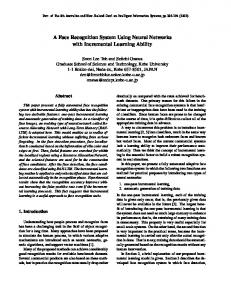
Figure 5. Face detection in images at different ages and with different expressions [IMG1] Face detection systems can be based on several cues: skin color (color images and video), motion (real-time face detection/video), facial/head shape, facial appearance or a combination of these. Enough successful face detection systems are appearance-based. In these systems the main problem is to classify each scanned sub-window as a face or a non-face [7]. A face/non-face classifier can be learned using a training set of images representing both faces and non196
Journal of Mobile, Embedded and Distributed Systems, vol. III, no. 4, 2011 ISSN 2067 – 4074 faces. This training is possible because pixels on a face are highly correlated, while those in a non-face sub-window present a high irregularity. Efforts were been made for constructing complex fast classifiers. As a face detection solution for the proposed face recognition system, the Viola-Jones algorithm has been implemented.
2.3. The Viola-Jones detection system
2.3.1. Features Motivated by the work of Papageorgiou et al. [10], Viola and Jones use three types of simple features.
face
The Viola-Jones [8,9] face detection system is faster than the previously published solutions, being able to detect faces in 384x288 pixels images at 15 frames per second on a conventional 700 MHz Intel Pentium III. There are three main parts which together give the proposed solution.
Figure 6. Haar wavelet-like feature: (A) and (B) – two-rectangle feature, (C) – three-rectangle feature, and (D) – four-rectangle feature. [9]
The first part is a new image representation called an integral image that allows a very fast feature evaluation. The used features are reminiscent of Haar basis functions. For a fast processing of these features the integral image representation for images was introduced. The integral image can be computed from an image using a few operations per pixel. Once computed, any one of these Haar-like features can be computed at any scale or location in constant time. The second part is a method for constructing a classifier be selecting a small number of important features using AdaBoost learning algorithm. Within an image sub-window the total number of Haar features is far larger than the number of pixels. Thus, the large majority of the available features is excluded and the focus is pointed on a small set of critical features. Each stage of the boosting process can be viewed as a feature selection process. In the third part more complex classifiers are combined in a cascade structure, increasing the speed of the detector by moving the most complex processing on promising regions of the image.
A simple feature is a scalar. It is calculated by summing up the pixels in the white region and subtracting those in the dark region.
2.3.2 The ‘Integral image’ The rectangle features can be computed faster using an intermediate representation for the image, called integral image. The integral image at location x, y contains the sum of the pixels above and the left of x, y, as defined in [9]:
II ( x, y) =
∑ I ( x , y ), '
'
'
'
x ≤ x, y ≤ y
(5) where: II(x, y) is the integral image, and I(x, y) is the original image The integral image can computed in one pass over the original image with the following system of recurrence
197
www.jmeds.eu
S ( x, y ) = S ( x, y − 1) + I ( x , y ) II ( x, y) = II ( x − 1, y) + S ( x, y)
(6)
p i f i ( x ) < p iθ i
if
1 K i ( x) = 0
otherwise
(7) where: Ki(x)– weak classifier, fi(x) – feature, pi – parity: indicates the direction of the inequality sign, Ɵi – threshold, x – a 24 x 24 sub-window of the original image.
where: S(x, y) is the cumulative row sum, S(x, -1) = 0, II(-1, y) = 0. Thus, using the concept of integral image, any rectangular sum from the original image can be computed using four array references.
A representation algorithm [9] is:
of
the
AdaBoost
(1) The input A training set of images is given: T = {(x1, y1), …, (xn, yn)}, where 1, for positive examples yi = 0, for negative examples
(8)
(2) The initialization The weights are initialized:
Figure 7. Source [9]
ωi(0) =
In figure 7, in point (1) the value of the integral image is the sum of the pixels of rectangle A. In point (2), the integral image’s value is A+B. In point (3), it is A+C. In point (4), it is A+B+C+D. Thus, the rectangular sum in point D can be computed as 4+1 – (2+3) [9].
2.3.3. The algorithm
AdaBoost
ωi(0) =
1 for the positive examples (y i = 1) 2k (9)
1 for the negative examples (y i = 0) 2p (10)
where k + p = n.
learning
(3) The forward inclusion For r = 1, …, T: 3.1 The weights are normalized:
The second main contribution of the Viola-Jones method is the use of the AdaBoost learning algorithm for constructing strong classifiers. The AdaBoost algorithm, in its original form, is used to combine a collection of weak classification functions in order to build a strong classifier, but in the ViolaJones solution it will select the features, too. The weak learning algorithm determinates the optimal threshold classification function and selects the single rectangle which best separates the positive and negative examples.
ω
( i) r
=
ωrr
n
∑ω j =1
j r
(11) 3.2 A classifier kj, is trained for each feature fj and it restricted to use a single feature. According to ωr, the error is :
ε j = ∑ ω i | k j ( xi ) − y i | i
(12)
3.3 The classifier with the lowest error is chosen. 3.4 The weights are updated :
198
Journal of Mobile, Embedded and Distributed Systems, vol. III, no. 4, 2011 ISSN 2067 – 4074
ω
(i ) r +1
=ω
of classifiers increases, the threshold is adjusted to minimize the false negatives and the detection rate grows.
(i) β r1-ε i r (13)
where: εi = 0, if example xi is classified correctly εi = 1, otherwise
3. Face Recognition Using Eigenfaces The goal of a face recognition system is to discriminate input signals (image data) into several classes (persons), being important for a wide variety of problems like image and film processing, human-computer interaction, criminal identification and others. The inputs signals can be highly noisy because of different lightning conditions, pose, expression, hair…. Nevertheless, the input signals are not completely random and even more, there are patterns present in each input signal. One can observe in all input images common objects like: eyes, mouth, nose and relative distances between these objects. These common features are called eigenfaces [11] in the facial recognition domain (or principal components generally). They can be extracted out of the original image data through a mathematical technique called Principal Component Analysis (PCA).
ε βr = r 1 −εr
(4) The output The final classifier (strong classifier) is: T 1 T 1, if ∑ α r k r ( x ) ≥ ∑ αr k (x) = 2 r =1 r =1 0, otherwise
where:
α r = log
(14)
1
βr
. (15)
2.3.4 The cascade structure of strong classifiers A two – rectangle classifier can be adjusted to detect 100% of the faces with a false positive rate of 40%. This means, a single classifier will not be enough to meet the system requirements. The solution for this is to implement a cascade of adjusted and trained classifiers.
3.1. Calculating Eigenfaces Given a face image I(x, y), it can be considered as a two-dimensional NxN array of intensity values. Also, an image can be normalized to a N2 vector. Thus, a typical image of size 256 by 256 becomes a vector of dimension 65.536, which can be thought as a point in a 65.536-dimensional space. Due to similarities of faces, a set of face images will map to a low-dimensional subspace of this huge space. Using principal component analysis (or Karhunen – Loeve expansion), the vectors, which best account for the distribution of face images within the entire image space, are found. These vectors are those which have the largest corresponding eigenvalue. They compose a subspace within the entire image space, called by Turk and
Figure 8. Cascade of strong classifiers [7] In the above cascade structure, the simplest boos-ted classifiers reject the majority of negative sub-windows and detect the positive instances. The next classifier will complete a more difficult task than the previous. As the numbers 199
www.jmeds.eu
Pentland [12] “face space”. Because they are the eigenvectors of the covariance matrix corresponding to the original face images, and because they are face-like in appearance, they are referred by Turk and Pentland [12] as “eigenfaces”.
Computationally, this is a not very efficient as most of these eigenfaces (eigenvectors) are not useful for the proposed task (having low-weights in reconstructing the original image). Consider the eigenvectors xi of ATA such that
If the training set of face images is Γ1, Γ2, …, ΓM, then the average face of the set is defined by
ψ =
1 M
(22) multiplying both sides by A, results
M
∑Γ i =1
i
(23)
(16)
where can be visible that Axi are eigenvectors of covariant matrix C = AAT. Following this analysis, L = ATA, a MxM matrix, is constructed, where
Each face differs from the average face by the vector
(17) This set of very large vector is the subject of PCA, which finds a set of M orthogonal vectors - v, which best describes the distribution of face images within the image space. The k-th vector, vi, is chosen such that
(24) and xi – M eigenvectors of matrix L are calculated. These vectors determine linear combinations of the M training set face images to form the eigenfaces vl.
(18) (25)
is a maximum, subject to
At this point the calculations are reduced from the number of pixel in images – N2 to the number of images in the training set – M (in practice M